A cam switch wiring diagram maps which terminal pairs close or open at each rotary detent position. For ON-OFF, changeover, voltmeter selector, and ammeter selector configurations, the diagram defines the contact truth table and the external circuit connections so panel builders can wire circuits correctly before energizing. This article covers all four configurations with step-by-step wiring procedures, contact tables, CT shorting requirements, and fault diagnosis guidance for industrial control panel engineers, panel builders, maintenance teams, and OEM buyers.
What a Cam Switch Wiring Diagram Shows
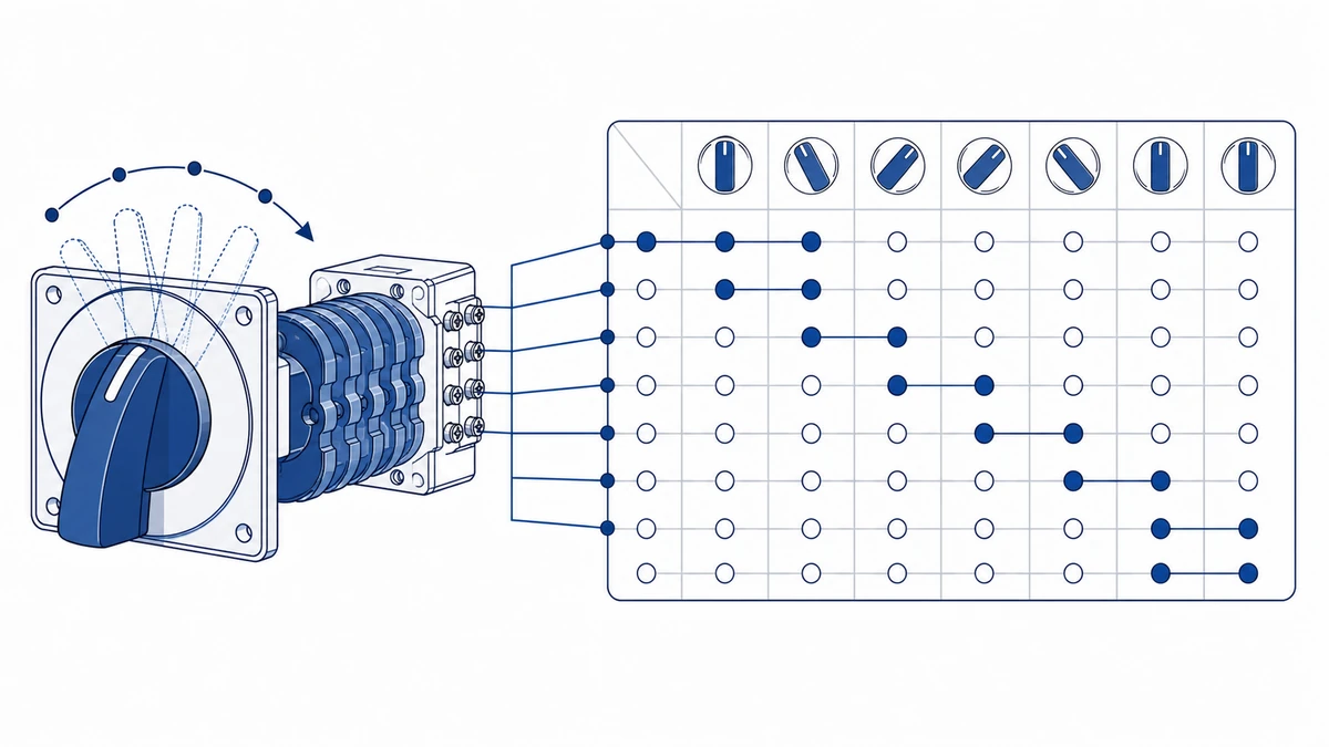
A поворотный кулачковый переключатель wiring diagram carries two layers of information: the contact truth table, which lists which terminal pairs are bridged at each position, and the external circuit connections, which show how load, source, and instrument terminals attach to those contacts. Together they define the switching logic without ambiguity.
In industrial control panels, engineers read the truth table first to confirm the number of poles and positions, then trace the external wiring to verify that no two live phases can be shorted during rotation. IEC 60947-3:2020+AMD1:2025 applies to switches, disconnectors, switch-disconnectors, and fuse-combination units for distribution and motor circuits, with rated voltage up to 1000 V AC or 1500 V DC. The rated operational current Ie and rated insulation voltage Ui defined under that standard must be matched to the circuit before wiring begins. The full standard text is available from the Веб-магазин IEC.
Four Configurations Covered in This Article
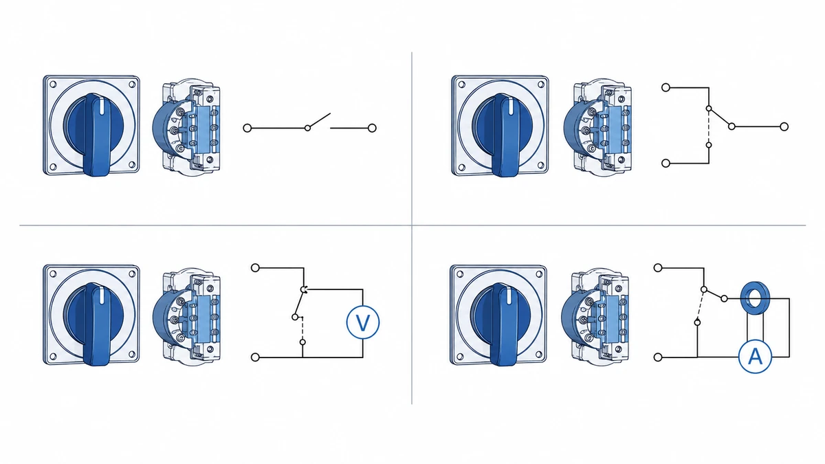
ON-OFF: Single or multi-pole isolation used to connect or disconnect a load from supply.
Changeover: Transfers a load or instrument between two sources without a make-before-break overlap on the load side.
Voltmeter selector: Routes one voltmeter across multiple phase-to-phase or phase-to-neutral measurement points using a multi-position cam sequence.
Ammeter selector: Inserts one ammeter into different current transformer (CT) secondary circuits, with shorting contacts that protect the CT when the meter is not in circuit.
Each configuration requires a distinct wiring diagram because the contact closure sequence differs between them.
The ON-OFF configuration is the starting point for understanding cam switch wiring. Once you can read a single-pole isolation diagram, the multi-pole and selector variants follow the same logic.
A cam switch ON-OFF wiring diagram shows how to connect a rotary selector switch to interrupt or restore current to one load circuit. In its simplest form, the switch has two positions — 0 (OFF) and 1 (ON) — and routes line voltage through a single contact bridge. The rated operational current for this duty is datasheet-dependent; confirm Ie and utilization category from the manufacturer’s product page before specifying.
Terminal Map
For a standard single-pole ON-OFF cam switch:
L1 (Terminal 1): Line input — connect phase conductor from upstream supply
T1 (Terminal 2): Load output — connect to load or downstream device
PE: Protective earth — connect to enclosure ground bar
For a three-phase version, repeat the pattern across three pole pairs: terminals 1/2, 3/4, and 5/6, with L1/L2/L3 entering odd-numbered terminals and T1/T2/T3 exiting even-numbered terminals.
Пошаговая процедура подключения
Step 1 — Isolate supply
De-energize the upstream circuit breaker and verify zero voltage with a calibrated meter before touching any conductors.
Step 2 — Mount the switch
Secure the cam switch in a panel cutout sized to the switch body. The Поворотный кулачковый переключатель LW28 uses a 30 mm mounting format; confirm the exact cutout dimension and fixing torque from the LW28 datasheet before installation.
Step 3 — Connect line conductors
Insert phase conductors into odd-numbered input terminals (1, 3, 5). Tighten to the manufacturer’s specified torque for the conductor cross-section in use. Typical values for terminals rated 4-16 mm2 fall in the range of 1.2-2.5 Nm, but always verify against the product datasheet.
Step 4 — Connect load conductors
Insert load-side conductors into even-numbered output terminals (2, 4, 6). Maintain conductor color coding per IEC 60446: brown/black/grey for L1/L2/L3, green-yellow for PE.
Step 5 — Verify contact continuity
With the switch in position 1 (ON), use a continuity tester to confirm each input terminal bridges to its paired output terminal. In position 0 (OFF), all bridges must read open.
Step 6 — Re-energize and function test
Restore supply voltage and cycle the switch between OFF and ON at least three times, confirming the load responds correctly at each position.
In industrial control panel builds, this ON-OFF configuration is commonly used as a local isolator ahead of a motor starter or transformer, giving maintenance personnel a defined off-state before opening the enclosure — a practice aligned with IEC 60204-1 requirements for machine electrical equipment.
ON-OFF Cam Switch: Field Notes
Always verify zero voltage at both input and output terminals after isolation. A downstream backfeed from a UPS or capacitor bank can hold voltage on the load side even with the switch open.
For three-phase motor isolator duty, select a switch rated for AC-23A utilization category, not AC-22A. The difference in making and breaking capacity is significant under inductive load conditions.
Torque all terminals to spec on first installation and re-check after the first 48 hours of operation. Thermal cycling causes conductor settling that loosens connections.
Label each switch position with a durable engraved legend plate, not adhesive labels. Adhesive degrades in environments above 60 degrees C.
Changeover Cam Switch Wiring Diagram
With the ON-OFF topology established, the changeover configuration extends that logic to transfer a circuit between two sources rather than simply interrupting one.
A changeover cam switch wiring diagram shows how a load or instrument is transferred between two supply sources through a rotary selector switch. In a standard break-before-make changeover configuration, rotating the switch through defined positions connects one source while opening the other, with no overlap that could parallel two live supplies.
How the Changeover Circuit Works
The changeover switch sits between the load or instrument and two input sources. Each switch position connects one input pair to the output while opening all other input paths. This prevents parallel measurement paths that would introduce measurement error or create unintended current loops — a common fault mode when changeover wiring is done incorrectly.
For a 3-position changeover switch (positions: OFF / Source 1 / Source 2), the contact state at each position follows this pattern:
Contact State Table — 3-Position Changeover
Позиция
Contact 1-2 (Source 1)
Contact 3-4 (Source 2)
Output
0 (OFF)
Открыть
Открыть
Isolated
1
Закрытый
Открыть
Source 1
2
Открыть
Закрытый
Source 2
For instrument-level changeover, contact resistance should remain stable against the commissioning baseline and the manufacturer acceptance criteria to avoid introducing measurement offset. Confirm the contact resistance specification from the manufacturer’s datasheet for the switch series in use.
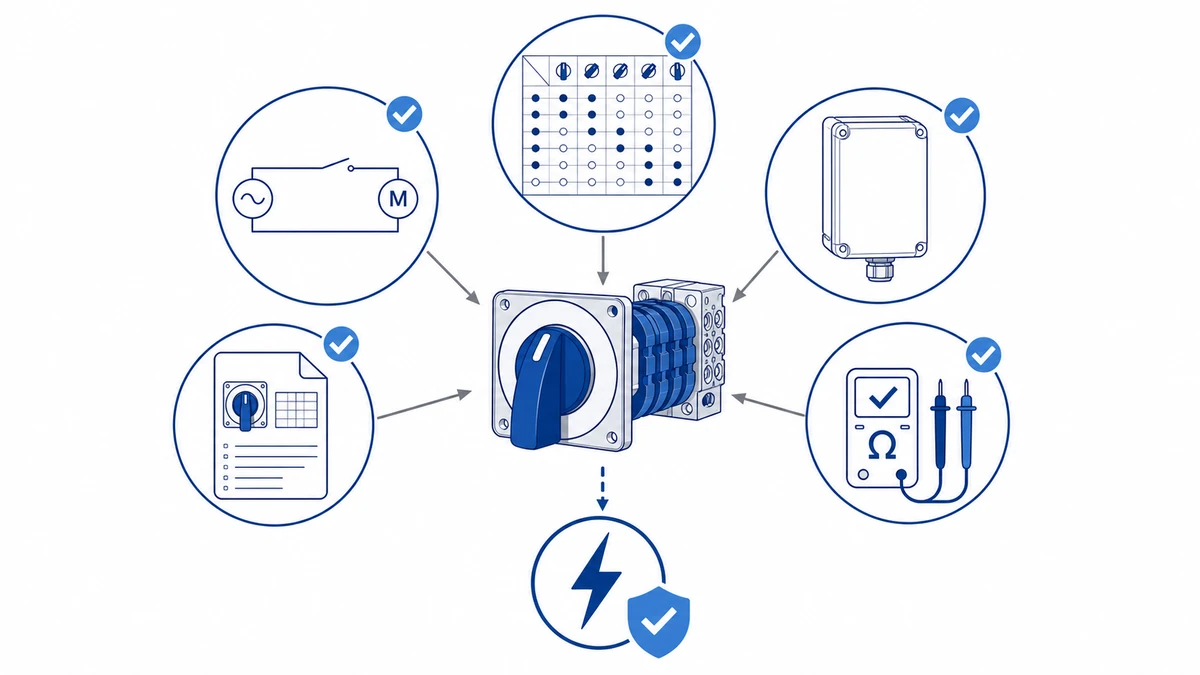
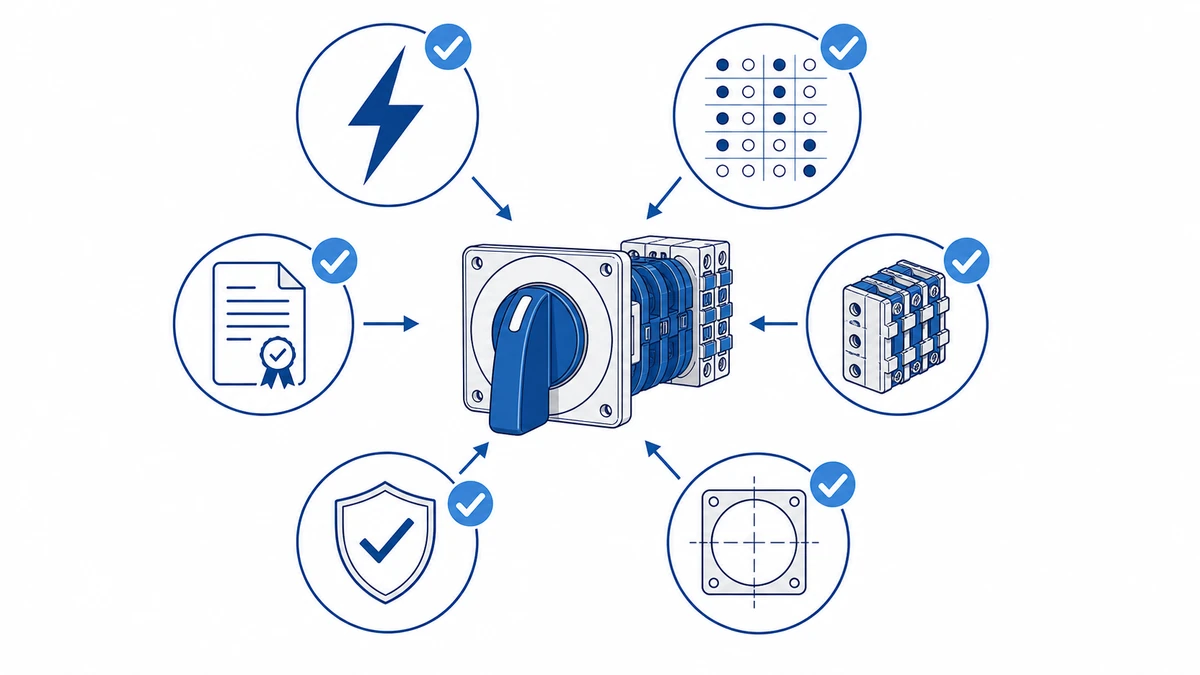
Рисунок 2. При выборе следует учитывать нагрузку, последовательность включения, корпус и требования к документации.
Voltmeter Selector Switch Wiring Diagram
The changeover principle scales directly into the voltmeter selector, where the switch steps through a defined sequence of phase pairs rather than just two sources.
A voltmeter selector switch wiring diagram shows how a multi-position rotary cam switch connects a single voltmeter to multiple measurement points in a three-phase system. The switch typically steps through 7 positions — OFF plus six measurement positions — covering both phase-to-phase (line-to-line) and phase-to-neutral readings from a single instrument.
Phase-to-Phase and Phase-to-Neutral Measurement Positions
In a standard three-phase, four-wire (3P+N) panel, the voltmeter selector switch routes voltage signals through potential transformer (PT) secondary terminals or directly from busbars. Each cam position closes a specific pair of contacts, connecting the voltmeter’s L+ and L- terminals to the selected phase pair. IEC 60038 defines standard voltages of 400 V AC line-to-line and 230 V AC line-to-neutral for low-voltage systems in the relevant voltage band.
Contact Truth Table — 7-Position Voltmeter Selector
Позиция
Label
Contact Pair Closed
Measurement
0
OFF
Нет
Isolated
1
U12
L1 to L2
Phase-to-phase
2
U23
L2 to L3
Phase-to-phase
3
U31
L3 to L1
Phase-to-phase
4
U1N
L1 to N
Phase-to-neutral
5
U2N
L2 to N
Phase-to-neutral
6
U3N
L3 to N
Phase-to-neutral
Wiring Notes for Field Installation
The voltmeter input impedance is typically 1 MOhm or higher, so contact current through the selector switch remains well below 1 mA. This is a purely voltage-sensing circuit with negligible load on the contacts. Standard rotary cam switches rated at AC-23A are significantly oversized for the electrical duty, but the mechanical robustness and positive detent action at each position are the primary selection criteria for this application.
Fuse each phase input to the selector switch with a 2A or 4A HRC fuse to protect the voltmeter and wiring against fault conditions. The neutral conductor connects directly to the voltmeter’s common terminal without switching.
IEC 60947-3:2020+AMD1:2025 requires that contact position be clearly indicated — a requirement met by the cam switch’s engraved position markings and spring-detent mechanism that holds each measurement position under vibration.
Рисунок 3. Перед подачей напряжения необходимо сверить контекст подключения с контактной схемой производителя.
Voltmeter Selector: Field Notes
Never omit the phase fuses on the selector switch inputs. A voltmeter fault or wiring error without upstream fusing can carbonize the switch contacts and damage the busbar insulation.
If the voltmeter reads correctly on phase-to-phase positions but floats or reads low on phase-to-neutral positions, the neutral conductor is either missing or landed on the wrong terminal. Check the N terminal first before suspecting the switch.
In panels with potential transformers, confirm the PT secondary voltage matches the voltmeter’s rated input range before energizing. A 110 V-rated voltmeter connected to a 400 V secondary will be damaged immediately.
Use a switch with a positive spring-detent mechanism in any panel subject to vibration. A switch that drifts between positions introduces intermittent measurement errors that are difficult to trace.
Ammeter Selector Switch Wiring Diagram with CT Integration
Where the voltmeter selector is a straightforward voltage-routing circuit, the ammeter selector introduces a hard safety constraint that changes the entire contact sequencing approach.
An ammeter selector switch wiring diagram for three-phase systems must account for one critical safety requirement that voltmeter circuits do not share: current transformer (CT) secondary circuits must never be left open-circuited. This single constraint shapes the entire wiring topology and contact sequencing of any ammeter selector switch installation.
Why CT Shorting Contacts Are Non-Negotiable
A current transformer operates with its secondary winding under near-short-circuit conditions during normal measurement. If the secondary circuit opens while primary current flows, the CT core can saturate and the secondary voltage can rise to dangerous levels; the exact voltage depends on CT ratio, burden, primary current, and installation conditions. IEC 61869-2, which governs instrument transformers including measuring CTs, requires that CT secondary terminals be shorted or connected to a burden at all times during energized operation.
For this reason, ammeter selector switches are specifically designed with make-before-break (shorting-type) contacts on the CT secondary paths. The shorting contact closes the non-selected CT secondaries before the selected path opens during rotation, ensuring the secondary circuit is never interrupted.
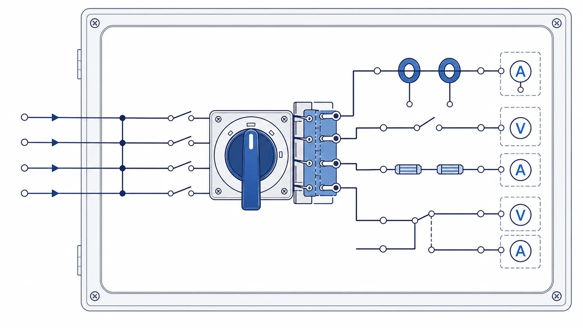
Contact Sequencing in a Three-Phase Ammeter Selector
In a typical three-phase ammeter selector circuit, three CTs are installed on phases L1, L2, and L3, each with a 5A secondary output. The cam switch — commonly a 4-position rotary cam switch with positions 0, L1, L2, L3 — routes one CT secondary at a time to the ammeter while simultaneously shorting the other two CT secondaries through dedicated shorting contacts.
Пошаговая процедура подключения
Step 1 — Connect CT secondary inputs
Connect each CT secondary S1 terminal to the cam switch input contacts for its respective phase position. S2 terminals share a common return to the ammeter and CT shorting bus.
Step 2 — Wire the shorting contacts
Wire the shorting contacts so that in every switch position, the non-selected CT secondaries have their S1-S2 terminals bridged internally through the switch contact matrix.
Step 3 — Verify position 0 shorting
In position 0 (off), all three CT secondaries must be shorted simultaneously — not left open. Verify this condition against the switch’s contact truth table before energizing.
Step 4 — Connect the ammeter
Connect the ammeter across the selected CT secondary output terminals. Panel ammeter input and burden values vary by meter model; confirm the burden rating against the CT’s rated burden before commissioning.
For panel builders sourcing switches for this application, the Серия LW28 и Серия LW42 rotary cam switches are available in ammeter-specific contact configurations with factory-verified shorting sequences. Always cross-reference the contact diagram supplied with the switch against IEC 61869-2 shorting requirements before commissioning.
Рисунок 4. Полный запрос должен включать номинал, последовательность контактов, монтаж, корпус и требования к документам.
Cam Switch vs. Rotary Selector Switch: Which to Use and When
Knowing how each configuration is wired makes the selection decision straightforward. The application’s current level and CT requirements point directly to the right device.
Cam switches and rotary selector switches are often confused because both use a rotating actuator to switch between circuit states. The practical difference comes down to contact capacity, position flexibility, and whether the application involves CT circuits.
A standard rotary selector switch is generally rated for signal-level or light-duty loads and suits PLC input selection or indicator changeover. A cam switch is built for power-level switching under IEC 60947-3 utilization categories. CT shorting is a hard requirement in ammeter selector circuits. Cam switches designed for ammeter service include a make-before-break contact sequence that shorts the CT secondary before disconnecting the meter — a feature absent in most standard rotary selector switches.
Comparison Table: Cam Switch vs. Rotary Selector Switch
Параметр
Cam Switch
Поворотный селекторный переключатель
Contact capacity
Power-level; confirm Ie from datasheet
Typically signal or light-duty
Position count
4-12 positions typical
2-6 positions typical
CT shorting capability
Yes (make-before-break)
Generally no
Governing IEC standard
IEC 60947-3
IEC 60947-5-1
Типичное применение
Voltmeter/ammeter selector, motor changeover
PLC input selection, indicator switching
If your application is limited to signal-level changeover with no CT involvement, a rotary selector switch is the lower-cost, simpler choice. If the circuit involves power-level switching or CT secondary routing, a cam switch rated under IEC 60947-3 is the correct device.
Troubleshooting Cam Switch Wiring Faults
Even a correctly specified switch will produce faults if the wiring deviates from the diagram. The patterns below cover the failures that appear most often during panel commissioning and first energization.
Fault 1: Meter reads zero in all switch positions
Check: Supply voltage present at cam switch input terminal (measure phase-to-neutral, expect 230 V AC or 400 V AC line-to-line depending on measurement point)
Check: Common terminal continuity — an open common is the most frequent single cause of total meter loss
Corrective action: Re-terminate common wire with correct ferrule; torque to manufacturer spec
Fault 2: Meter reads correctly in one position but not others
Check: Contact diagram against actual wiring — a misrouted wire on a secondary output terminal causes selective position failure
Check: Contact resistance on the suspect position; elevated values indicate worn or oxidized contacts
Corrective action: Clean contacts with dry contact spray or replace the switch if contact resistance cannot be restored
Fault 3: Ammeter deflects backward
Check: CT polarity — S1/S2 terminals reversed at either the CT or the switch
Corrective action: Swap S1 and S2 connections at the cam switch terminal block; never open a CT secondary under load
Fault 4: Voltmeter reads phase-to-phase instead of phase-to-neutral
Check: Neutral terminal connection at the switch — a missing neutral wire forces the meter to float across two phases
Corrective action: Verify neutral is landed on the correct terminal per the wiring diagram
Fault 5: Switch position feels correct but circuit does not change
Check: Cam disc seating — a loose actuator shaft can allow the handle to rotate without engaging the cam mechanism
Corrective action: Inspect shaft retention and replace the switch if cam slippage is confirmed; the LW28 and LW42 series use a keyed shaft design that resists this failure mode
For replacement parts or technical support, browse the full rotary cam switch range at Shieldhz to find a correctly rated selector switch for your panel.
How Shieldhz Checks Cam Switch Wiring Before Production
Shieldhz wiring support starts from the contact truth table. For ON-OFF, changeover, voltmeter selector, and ammeter selector circuits, the team checks which terminal pairs must close at each handle position, whether any bridge timing matters, and whether CT secondary safety provisions are required. This reduces the risk of ordering a switch that has the right number of positions but the wrong contact sequence.
Before production or quotation confirmation, buyers should send the circuit sketch, desired handle labels, instrument transformer details where relevant, operating voltage, and panel terminal-marking preference. Shieldhz can then align the cam program, terminal layout, and documentation package so the panel builder can test continuity before energizing the cabinet.
Часто задаваемые вопросы
What is the difference between a cam switch and a rotary selector switch?
A cam switch is rated for power-level switching and is governed by IEC 60947-3. It includes CT shorting contact sequences for ammeter selector duty. A rotary selector switch handles signal-level or light-duty loads and is governed by IEC 60947-5-1. The two devices are not interchangeable in CT secondary circuits.
Can a cam switch be wired without a contact truth table?
Wiring a cam switch without its contact truth table risks shorting live phases during rotation or leaving CT secondaries open-circuited, both of which are safety hazards. Always obtain the manufacturer’s contact diagram for the specific switch code before wiring. The diagram is part of the procurement documentation and should be retained with the panel records.
Why must CT secondary circuits never be open-circuited?
When primary current flows through a CT and the secondary circuit is open, the core can saturate and the secondary voltage can rise to dangerous levels. The exact voltage depends on the CT and circuit conditions. IEC 61869-2 requires the secondary to remain shorted or connected to a burden at all times during energized operation. Ammeter selector cam switches address this through make-before-break shorting contacts.
How many positions does a voltmeter selector switch typically have?
A standard three-phase, four-wire voltmeter selector switch uses 7 positions: one OFF position and six measurement positions covering the three phase-to-phase voltages (U12, U23, U31) and three phase-to-neutral voltages (U1N, U2N, U3N). Some panels use a 4-position switch covering only phase-to-phase measurements; confirm the required measurement points before specifying.
What torque should be used when terminating conductors on a cam switch?
Terminal torque depends on the conductor cross-section and terminal size. Always follow the manufacturer’s datasheet for the specific switch series. Applying a generic torque value without checking the datasheet risks under-tightening, which causes resistive heating, or over-tightening, which damages the terminal.
How do I confirm a cam switch is wired correctly before energizing?
With the supply isolated, use a continuity tester to step through each switch position and verify that the correct terminal pairs are bridged and all others are open, comparing each result against the contact truth table. For ammeter selector switches, also confirm that non-selected CT secondaries are shorted in every position including OFF. Document the results as part of the panel commissioning record.
What fuse rating should be used on voltmeter selector switch inputs?
Each phase input to a voltmeter selector switch should be protected by a fuse selected for the meter circuit and the panel fault level. The neutral conductor connects directly to the voltmeter’s common terminal and does not require switching or fusing. Fuse selection should also account for the prospective short-circuit current at the installation point; confirm the fuse breaking capacity is adequate for the panel’s fault level.