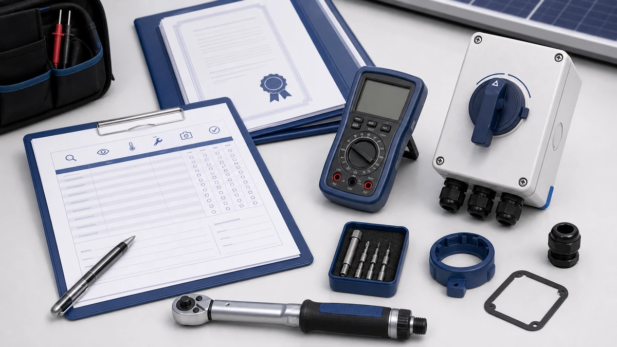
Контрольный список по техническому обслуживанию разъединителей постоянного тока для солнечных фотоэлектрических систем
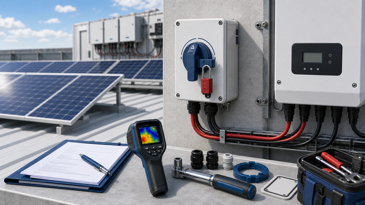
Техническое обслуживание разъединителей постоянного тока включает в себя проверку следов перегрева, проникновения влаги, износа контактов, состояния рукоятки, этикеток, а также соответствующей документации по техническому обслуживанию.
A structured DC isolator switch maintenance checklist is the first line of defence against arc-induced contact failure, thermal runaway at terminals, and moisture ingress in outdoor PV enclosures. Solar installers and maintenance teams working on string-level or array-level systems need a repeatable inspection protocol because DC strings from photovoltaic panels maintain open-circuit voltage continuously — even with the inverter off. This guide delivers a field-ready checklist, recommended inspection intervals, failure-mode reference points, and procurement documentation guidance aligned with официальная публикация МЭК по выключателям-разъединителям, the international standard that governs switches, disconnectors, switch-disconnectors, and fuse-combination units rated up to 1000 V AC or 1500 V DC.
Why DC Isolator Switch Maintenance Cannot Be Deferred
In any rooftop or ground-mount PV installation, the solar string presents continuous open-circuit voltage as long as light falls on the panels. There is no upstream off state from the source side. The DC isolator switch is therefore the only means by which a maintenance technician can create a verified, locked-out de-commissioned condition between the array and the inverter.
This functional role makes it a life-safety device, not a convenience component. DC switching imposes arc energy on contact surfaces that AC switches of equivalent current rating are not required to handle in the same way. Each operation cycle — whether a routine shutdown, a fault interruption, or a system recommission — deposits energy on the contact bridge, stresses the spring mechanism, and applies thermal load to the terminal block. When that accumulated damage goes uninspected, three failure modes become probable.
The first is welded contacts that prevent the switch from reaching the isolated position under manual or emergency conditions. The second is a high-resistance joint at one or more terminals, which generates localized resistive heating that can damage adjacent wiring, degrade the enclosure seal from the inside, and in worst cases contribute to a fire event. The third is enclosure seal degradation that allows moisture ingress, which accelerates contact oxidation and can reduce insulation resistance below levels required to sustain rated voltage.
switch-disconnector standard context is directly relevant here: the standard requires that a switch-disconnector maintain its making and breaking capacity and its insulation resistance across its declared service life. Without a documented maintenance schedule, neither condition can be confirmed in the field, and warranty or liability arguments become difficult to sustain.
DC Isolator Switch Maintenance Checklist: Full Inspection Protocol
The following protocol applies to string-level and array-level PV DC isolator switches installed in rooftop and ground-mount systems. Work only with the system de-commissioned and bus voltage verified at or near 0 V DC using a calibrated instrument before opening any enclosure.
Граница безопасности: This checklist is not a live-work instruction. PV DC isolator inspection, testing, torque checks, and replacement decisions should be handled by qualified electrical personnel under the site maintenance procedure. Before opening an enclosure, follow lockout/tagout, de-energize the relevant circuit where the procedure requires it, and verify absence of voltage with suitable DC-rated test equipment.
Step 1: Pre-Inspection Safety Verification
Confirm inverter shutdown and measure DC bus voltage at the isolator output terminals. Record the reading. If voltage is above a safe threshold defined by your site safety procedure, do not proceed.
Apply lockout and tagout to the isolator in the OFF position according to site procedures and local electrical safety regulations. Record the ambient temperature and relative humidity at the time of inspection. Inspections conducted above approximately 85 percent relative humidity may produce elevated insulation resistance readings that do not reflect the true condition of the device at operating temperature.
Step 2: Enclosure and Ingress Assessment
Examine the enclosure body on all four sides and the lid for cracks, UV yellowing, stress whitening, or visible deformation around mounting bosses. A crack wider than approximately 0.5 mm near a cable entry or lid seating groove is a fail condition that warrants replacement rather than continued service.
Check the lid gasket for hardening, compression set, or displacement. Press lightly on the lid corners before unlatching: a gasket that has retained elastic recovery will show even resistance; a hollow response or audible creak indicates the material has hardened and is no longer providing a continuous seal. On weatherproof outdoor installations, understanding the relevant IP rating checks helps define the minimum acceptable seal condition for the environment. Verify all cable entry glands for continuous contact and check that gland locknuts are finger-tight plus the torque increment specified by the gland manufacturer.
Inspect mounting fasteners for looseness. Thermal cycling between day and night temperatures causes enclosure flex, and relaxed fasteners allow gasket micro-movement that bypasses the stated IP rating over time.
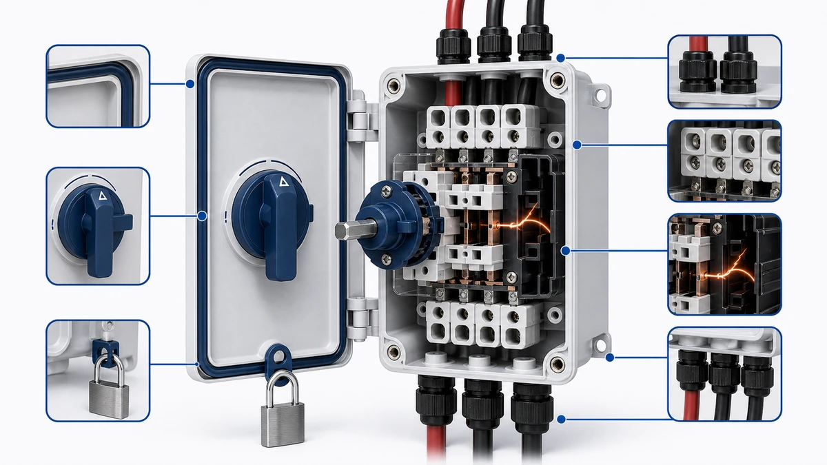
Step 3: Contact and Terminal Inspection
With the enclosure open and the switch confirmed in the OFF and locked-out state, examine all accessible terminals for oxidation, pitting, or carbon tracking. A healthy contact surface appears silver-grey with a uniform finish. Black carbonization, a green oxide layer, visible arc erosion pits, or discoloration of adjacent insulation are all fail conditions.
Measure contact resistance limit stated in the datasheet or maintenance procedure across each pole using a low-resistance ohmmeter or a milliohm meter. Compare the reading against the value recorded at the previous inspection and against the value stated in the manufacturer’s datasheet. A single elevated reading may indicate a surface film; a reading that has increased significantly since the last inspection indicates progressive contact degradation that should be investigated before the next scheduled interval.
Check terminal screw torque against the torque value specified in the device datasheet. Under-torqued connections at current ratings above approximately 16 A are among the most common sources of resistive heating leading to insulation damage and premature enclosure seal failure from internal thermal load. Do not apply torque values from memory or from a different product family — always verify against the specific device datasheet.
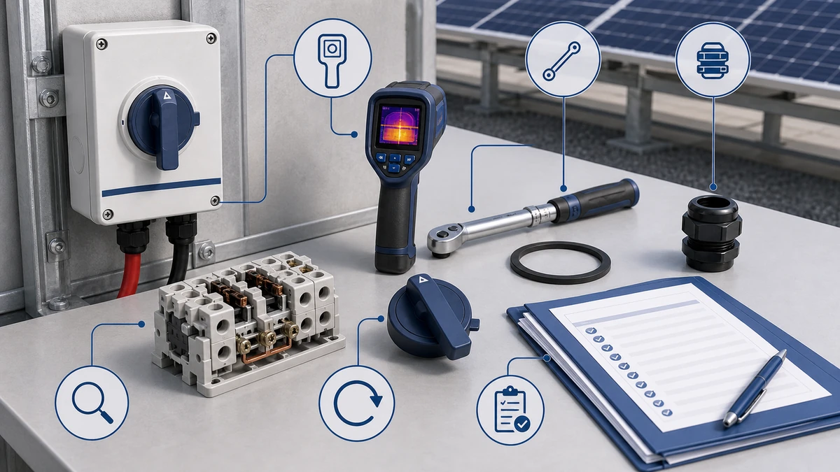
Рисунок 2. При выборе следует проверить постоянное напряжение, ток в сети, количество полюсов, корпус, кабельный ввод и документацию.
Step 4: Mechanical Operation Check
With the lockout removed for this step and the circuit confirmed de-commissioned, cycle the actuator handle through OFF, ON, and back to OFF a minimum of three times. Each position change should produce a positive detent engagement. The handle should travel to the end of its defined arc without stiffness, and the OFF position should hold without requiring manual retention against spring-back.
Binding, incomplete travel, a handle that fails to stay in the OFF position, or a click that is absent at one pole are all fail conditions. Document which position the fault occurs in for the service record.
Inspect the actuator shaft and handle root for corrosion, UV chalking, or cracks at the mechanical interface. Outdoor rooftop units with more than five years of service and no prior actuator inspection should be treated as candidates for replacement on the next maintenance cycle regardless of current visual appearance.
Confirm that polarity labeling at input and output terminals matches the as-built wiring diagram. DC polarity errors in solar strings are a persistent cause of contact damage and inverter input faults. Verify that conductor insulation at the terminal entry points shows no cracking, discoloration, or mechanical abrasion caused by movement under thermal cycling.
Check that any warning labels required by the installation standard — including DC live voltage warnings — remain legible. Faded or missing labels are a compliance issue in addition to a safety concern.
Step 6: Documentation and Record Update
Record all readings, pass or fail outcomes, torque values applied, and any component replacements in the site maintenance log. Include the inspection date, inspector identification, ambient conditions, and the next scheduled inspection date. Photographic documentation of terminal condition and enclosure seal state provides an objective baseline for trend analysis across successive inspections.
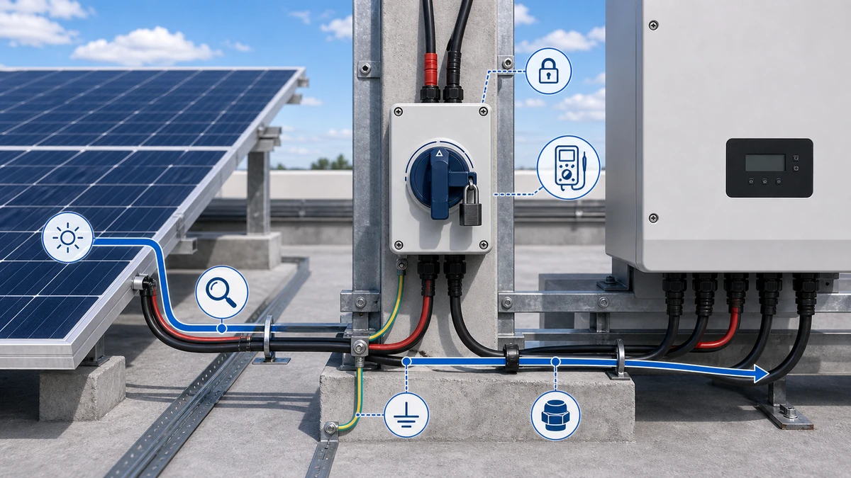
Рисунок 3. Перед подачей напряжения необходимо сверить контекст подключения с контактной схемой производителя.
How Often Should DC Isolators Be Inspected?
Inspection interval selection is as consequential as the checklist itself. Interval errors in either direction carry costs: too infrequent allows undetected degradation to progress to failure; too frequent adds unnecessary labour cost and increases the probability of reinstallation errors.
The appropriate interval depends on three converging inputs: the installation environment, the system voltage tier, and the maintenance intervals specified in the warranty documentation for the specific device and for the inverter or combiner box it is connected to. Equipment warranty documentation should always be the primary reference — intervals stated here are reference guidance only and do not override manufacturer or project-specific requirements.
For installations in temperate or low-pollution environments at 1000 V DC or below, an annual visual and mechanical inspection combined with a contact resistance limit stated in the datasheet or maintenance procedure measurement is a commonly adopted baseline. For installations in coastal, high-humidity, industrial-atmosphere, or high-UV desert environments, a six-month interval for visual and enclosure integrity checks — with full electrical measurement annually — is a more defensible approach.
For utility-scale ground-mount systems operating at 1500 V DC, the combination of higher arc energy per switching event and greater financial consequence of unplanned downtime typically justifies a semi-annual full inspection schedule.
After any fault event — inverter ground fault, string overcurrent, or lightning-associated surge — an immediate unscheduled inspection of the DC isolator switch at the affected string position should be treated as mandatory, not discretionary.
Common Failure Indicators and When to Replace Rather Than Repair
Maintenance teams sometimes attempt to clean oxidized contacts or re-torque terminals as a corrective action when replacement is the correct outcome. The following conditions should be treated as replace-not-repair decisions.
Contact surfaces with arc erosion pits that have measurably reduced the contact bridge cross-section are beyond cleaning. A contact resistance limit stated in the datasheet or maintenance procedure measurement that remains elevated after cleaning and re-torquing indicates the substrate itself has been compromised. An actuator that binds or fails to hold position after lubrication of the shaft pivot point indicates mechanical wear of the detent mechanism that field service cannot correct. An enclosure with a permanently deformed gasket groove or a cracked lid will not recover its IP rating through gasket replacement alone if the mating surface is no longer flat.
When evaluating replacement options, the GF41 солнечный выключатель постоянного тока is worth reviewing for applications where the rated current, pole count, or enclosure class of the originally installed unit no longer matches the system configuration due to array expansion or re-stringing.
Understanding what a DC switch disconnector is and how it differs from a load-break switch or a fuse-combination unit is relevant when specifying a replacement — the DC switch disconnector overview provides a reference for confirming the correct device category before procurement.
Рисунок 4. Полный запрос должен включать номинал, последовательность контактов, монтаж, корпус и требования к документам.
How Shieldhz Confirms Model Selection, Ratings, and Documentation for PV DC Isolator Maintenance Inquiries
Shieldhz is the export brand of Zhejiang Shihe Electric Co., Ltd., founded in 2014 and based in Yueqing, Wenzhou, Zhejiang — a region with established industrial electrical manufacturing infrastructure. The facility operates across more than 5,000 square metres with over 100 employees and 40 or more dedicated production machines. The quality system is certified to ISO 9001, and the product range carries CE, TUV, RoHS, UL, UKCA, CCC, and CB certifications depending on the specific product and market.
When a solar installer, maintenance contractor, or OEM buyer submits an inquiry for a DC isolator switch — whether for initial procurement, like-for-like replacement, or an upgrade following array expansion — the Shieldhz engineering and sales team works through a structured confirmation process before issuing a final recommendation.
The first step is rating confirmation: the team verifies the system DC voltage tier, the maximum string short-circuit current, and the required breaking capacity against the specific product datasheet to confirm the utilization category is appropriate for the application. the current switch-disconnector standard edition defines utilization categories for DC switch-disconnectors, and the correct category must be matched to the switching duty — this is not a generic selection.
The second step is the contact program and wiring diagram review. For maintenance-driven replacements, the team confirms that the replacement unit’s terminal layout, pole sequence, and conductor entry orientation are compatible with the existing installation wiring to avoid reinstallation errors that could introduce polarity faults or reduce conductor clamping area.
Third, the enclosure and IP specification is reviewed against the installation environment described by the buyer. Coastal, high-UV, or high-particulate environments warrant a higher IP class or additional UV-stabilized enclosure material, and the team confirms which product variant in the range meets that requirement.
Fourth, the documentation package is confirmed before shipment. Buyers requiring test reports, certificate copies, dimensional drawings, or customs documentation for import compliance can specify those requirements at inquiry stage. The team confirms availability and format before order confirmation.
Solar installers and panel builders who need to verify a maintenance replacement or confirm a specification for a new installation are encouraged to submit inquiry details including system voltage, current rating, pole count, enclosure class, and any certification requirements to the Shieldhz team for a documented product recommendation.
Часто задаваемые вопросы
What is the minimum inspection frequency for a DC isolator switch in a rooftop PV system?
Inspection frequency depends on the installation environment, device manufacturer documentation, and project warranty requirements. In a temperate low-pollution environment at 1000 V DC, annual inspection is a widely used baseline. Coastal, high-humidity, or high-UV installations commonly justify six-month visual checks with annual electrical measurement. Always verify against the specific device warranty documentation and applicable project maintenance specification — these take precedence over generic guidance.
Does the DC isolator switch need to be replaced after a string fault event?
An unscheduled inspection is required after any fault event that may have caused the isolator to interrupt a fault current. If the contact resistance limit stated in the datasheet or maintenance procedure measurement shows a significant increase compared to the baseline, if arc erosion pits are visible, or if the actuator mechanism shows signs of impact, replacement is the appropriate outcome. Continuing to use a device that has interrupted a fault current without inspection is not a defensible maintenance practice.
What does the utilization category mean for a PV DC isolator switch, and why does it matter for maintenance?
The utilization category defined under the current switch-disconnector standard edition specifies the switching duty the device is designed to perform — including the relationship between rated current, making capacity, and breaking capacity. For maintenance teams, the utilization category determines whether the device is rated to break the specific combination of current and voltage present in the string configuration. A device that has been operated outside its utilization category will show accelerated contact degradation detectable during inspection.
Can a DC isolator switch rated for 1000 V DC be used in a 1500 V DC system?
No. The device voltage rating is a maximum, not a design margin. Operating a 1000 V DC rated device in a 1500 V DC string creates a situation where the device cannot reliably interrupt the circuit under fault conditions, and insulation distances are no longer adequate. Confirm the voltage rating from the product datasheet before any replacement procurement.
How do I confirm the IP rating of a DC isolator switch is still valid after years of outdoor service?
IP rating validity cannot be assessed by visual inspection alone in all cases. The lid gasket compression set, the integrity of cable entry glands, and the enclosure body condition together determine whether the original IP class is maintained. A gasket that has hardened and no longer makes continuous contact with the lid seating surface has lost its sealing function regardless of its visual appearance. Physical testing per IEC 60529 is the only definitive confirmation — in practice, maintenance teams apply pass/fail criteria based on gasket resilience, crack width, and gland continuity as documented in this checklist.
What documentation should be collected when replacing a DC isolator switch on a certified PV installation?
At minimum, collect the product datasheet confirming the voltage rating, current rating, utilization category, and enclosure IP class of the replacement unit; a copy of the relevant test certificate or declaration of conformity; and the dimensional drawing confirming compatibility with the existing enclosure or panel cutout. For installations subject to grid connection approval or insurance review, the certificate format required by the authority having jurisdiction should be confirmed before procurement.
What is the difference between a DC isolator switch and a DC switch-disconnector?
A DC isolator switch in a PV context is typically a switch-disconnector — a device that can both make and break current under load and provide a visible or positively indicated isolation gap. A pure disconnector or isolator is not intended to be operated under load and is used only when the circuit has been de-commissioned by another means. For most solar string and combiner box applications, a switch-disconnector with appropriate utilization category for PV use is the correct device. Confirming the device category before procurement prevents specification errors that are difficult to detect during installation but visible during maintenance inspection.
Резюме
A disciplined DC isolator switch maintenance checklist — covering enclosure integrity, contact resistance limit stated in the datasheet or maintenance procedure, terminal torque stated in the datasheet or maintenance procedure, mechanical operation, and wiring verification — is the most effective tool available to solar installation and maintenance teams for preventing arc-induced contact failure, resistive heating events, and moisture-related insulation degradation. Inspection intervals should be set against manufacturer documentation and installation environment severity, not generic assumptions. When devices show fail conditions on contact, mechanical, or enclosure criteria, replacement is the correct response. Procurement decisions for replacement units should be driven by confirmed datasheet data, utilization category, and documentation package, not catalogue number alone.
Ши, Мукси
Ши, Мукси пишет технические статьи Shieldhz для покупателей промышленных систем управления и электрических компонентов, охватывая поворотные кулачковые переключатели, разъединители, PV DC разъединители, кнопки, индикаторные лампы, водонепроницаемые корпуса и клеммные блоки. Статьи основаны на опыте производства и экспорта компании Zhejiang Shihe Electric Co., Ltd., с практическим акцентом на выборе модели, технических характеристиках, чертежах, сертификации, рейтингах IP и деталях запроса, которые покупатели должны подтвердить перед заказом.