Контакты кнопок «NO» и «NC»: основы работы нормально открытых и нормально закрытых контактов
Контакты NO и NC обеспечивают противоположное поведение системы управления. Цепи запуска, остановки, сброса и сигнализации неисправности зависят от выбора подходящего контактного блока.
A normally open (NO) push button contact is open at rest and closes the circuit when pressed. A normally closed (NC) push button contact is closed at rest and opens when pressed. These two contact types are the fundamental building blocks of every industrial control circuit, from motor start/stop logic to emergency stop loops. Selecting the wrong type produces either a non-functional circuit or, in safety-critical applications, a machine that cannot be reliably de-energized. This guide explains the switching mechanics, IEC schematic conventions, terminal numbering, selection criteria, common wiring errors, and procurement inputs that panel engineers and OEM buyers need before specifying any NO NC push button contacts for a control panel.
What Are NO and NC Push Button Contacts?
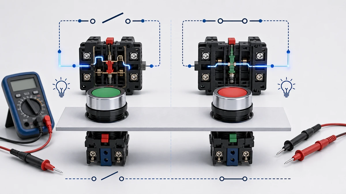
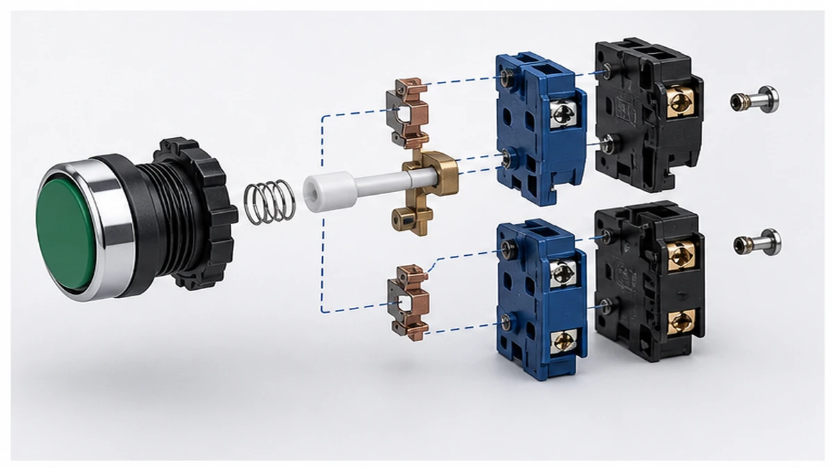
A push button contact block contains a movable conductive bridge and two fixed terminal pads. The only variable that defines the contact type is where that bridge sits when the button is at rest.
In a normally open contact, the bridge is held physically separated from the fixed terminals by a return spring. No current flows at rest. Pressing the actuator drives the bridge into contact, closing the circuit. Releasing the button allows the spring to restore the bridge to the open resting position.
In a normally closed contact, the bridge rests against both fixed terminal pads, maintaining a continuous current path. Pressing the actuator displaces the bridge away from the terminals, interrupting the circuit. Releasing the button restores continuity.
Both states are defined in reference to the de-energized, unactuated position of the button. Every NO and NC designation in a schematic or manufacturer datasheet describes the contact condition before any force is applied to the actuator — this is the reference convention in IEC 60947-5-1, the standard that governs low-voltage control circuit devices and switching elements, including rated operational current, making and breaking capacity, mechanical endurance, and contact gap requirements.
Understanding the mechanics in terms of circuit behavior — not just physical movement — is what makes the correct selection decision straightforward.
Normally Open Contact Logic
With no actuation force applied, the circuit path across an NO contact measures open. The contact gap in the unactuated state is maintained at a defined minimum to ensure reliable isolation at rated insulation voltage; the exact value is a design parameter confirmed in the manufacturer datasheet, not a universal constant. When an operator presses the button, the moving bridge closes against the fixed contacts, completing the circuit. Current flows only for the duration of active button engagement. Releasing the button restores the open state.
This logic makes NO contacts the standard selection for start commands, momentary triggers, and pulse inputs — any function where the default circuit condition must be de-energized and current flow requires a deliberate action.
Normally Closed Contact Logic
An NC contact reverses the spring logic. The bridge is held in continuous contact with both terminal pads at rest. The contact resistance in the closed resting state is a function of contact force, contact material, and operating conditions; the acceptable range for a given contact block under its rated load is specified in the manufacturer datasheet and should be verified with a low-resistance ohmmeter at commissioning rather than assumed from a generic figure.
Pressing the button forces the bridge off the terminals, breaking the circuit. Releasing the button closes it again.
The behavior on failure is what makes NC contacts appropriate for safety functions. A wiring break, a disconnected conductor, or a spring failure all produce the same result as an intentional press: the circuit opens and the load de-energizes. This inherently fail-safe characteristic is why IEC 60204-1 — the machinery safety standard governing emergency stop loop integrity — requires NC contacts for emergency stop circuits. A broken wire cannot leave a machine energized if the contact was closed at rest.
Dual-Contact Push Button Assemblies
Many industrial push button assemblies mount both an NO and an NC contact block behind the same actuator head. A single plunger stroke actuates both blocks simultaneously. This configuration allows one button to start one circuit path and stop another in the same press — a common arrangement in motor forward/reverse interlocks and safety-door interlock ladder logic. Contact block positions in a stacked assembly follow IEC terminal numbering, described in detail in the wiring section below.
NO vs NC Contacts: Side-by-Side Selection Reference
The following table summarizes the parameters that determine which contact type belongs in a given circuit position.
Параметр
NO Contact
NC Contact
Rest state
Open, circuit inactive
Closed, circuit active
Actuated state
Closed, circuit active
Open, circuit inactive
Default current condition
No current flows
Current flows continuously
Typical function
Start, trigger, energize
Stop, E-stop, interlock
Failure mode
Opens on spring failure
Opens on spring or wiring failure
Inherently fail-safe?
Нет
Да
IEC terminal designation
13/14, 23/24, 33/34
11/12, 21/22, 31/32
Schematic symbol
Gap between two lines
Diagonal slash across bridged lines
Категория использования
AC-15 (AC) or DC-13 (DC) per IEC 60947-5-1
AC-15 (AC) or DC-13 (DC) per IEC 60947-5-1
The utilization category is a critical procurement parameter. AC-15 governs the control of AC electromagnetic loads such as contactor coils. DC-13 governs DC electromagnetic loads such as solenoid valves and PLC relay coils. Arc energy at break on DC-13 circuits is substantially higher than on AC-15 circuits at the same nominal current and voltage — confirming the correct utilization category in the manufacturer datasheet is not optional when the contact block is used on DC supply rails.
Selection Logic in Practice
For start-type commands — motor activation, solenoid energization, PLC input triggers — specify an NO contact. Current flows only when the operator presses, reducing the risk of unintended circuit closure from wiring faults or contact welding in the closed state.
For stop or safety functions — motor stop, emergency stop, safety interlock — specify an NC contact. A broken conductor or loose terminal fails the circuit into a de-energized, safe state rather than leaving the load energized.
For applications requiring both functions from a single actuator, specify a 1NO+1NC contact block combination. This is a standard product option in the Shieldhz SH-B2 push button switch series and eliminates the need for two separate panel cutouts to achieve complete start/stop logic.
Figure 2. Selection checks should connect operator size, contact type, lamp voltage, color, IP rating, panel cutout, and documentation.
Real-World Applications of NO and NC Contacts in Control Panels
The theory above becomes actionable when mapped to the specific circuit positions that appear in industrial panel layouts.
NO Contacts: Motor Start, Conveyor Triggers, and PLC Inputs
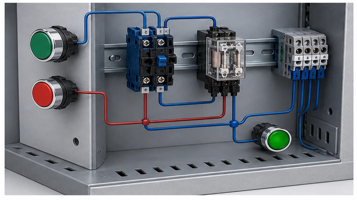
In a motor control center, a momentary NO push button is wired in series with the contactor coil circuit. Pressing START closes the NO contact, energizes the coil, and the contactor pulls in. A parallel auxiliary NO contact from the contactor itself latches the circuit, holding the motor in run state after the operator releases the start button. The push button carries only the coil control current — typically 24 V DC or 120 V AC at well under 1 A — not the motor load current. The low energy level means the contact block cycles through thousands of operations without the arc erosion that characterizes higher-energy switching.
In conveyor systems, packaging lines, and pump stations, NO contacts also appear on limit switches and selector switch positions where a circuit must remain open until a deliberate mechanical condition is met.
NC Contacts: Stop Commands, Emergency Stops, and Thermal Reset
An NC emergency stop button holds the contactor coil energized through a continuously closed circuit. Pressing the E-stop opens the NC contact, the coil voltage drops to zero, and the contactor releases. Standard AC contactors per IEC 60947-4-1 specifications are designed to release within a defined time window after the coil circuit opens — the exact figure for a specific contactor model is confirmed in that product’s datasheet, not assumed from a generic value. The critical safety property is that a broken wire or failed connection produces the identical result: the machine stops.
Thermal overload relay reset buttons also use NC contacts in many panel layouts. The NC contact in the reset circuit allows the operator to manually re-enable the contactor coil only after the thermal element cools and the fault clears, preventing automatic restart after an overload trip.
Dual-Contact Push Buttons with Integrated Indication
A common panel arrangement combines an NO contact for a run command with an NC contact for a fault interlock, both behind a single 22 mm push button head. When a panel indicator lamp module is integrated into the same actuator assembly, the NC contact can drive a status lamp to signal a de-energized condition while the NO contact drives the restart input. This configuration reduces the panel cutout count and keeps related logic co-located on the panel face. The lamp module voltage rating must be confirmed against the control supply voltage before assembly — a mismatch destroys LED modules silently without affecting contact function.
Рисунок 3. Перед подачей напряжения необходимо сверить контекст подключения с контактной схемой производителя.
A panel builder must be able to read the schematic and map it to the physical contact block before touching a conductor. The IEC conventions that govern push button symbols and terminal numbering are consistent across manufacturers, making cross-supplier drawings readable without translation once the conventions are understood.
IEC Schematic Symbols for NO and NC Contacts
Under IEC 60617, the standard graphic symbols used in electrical schematics:
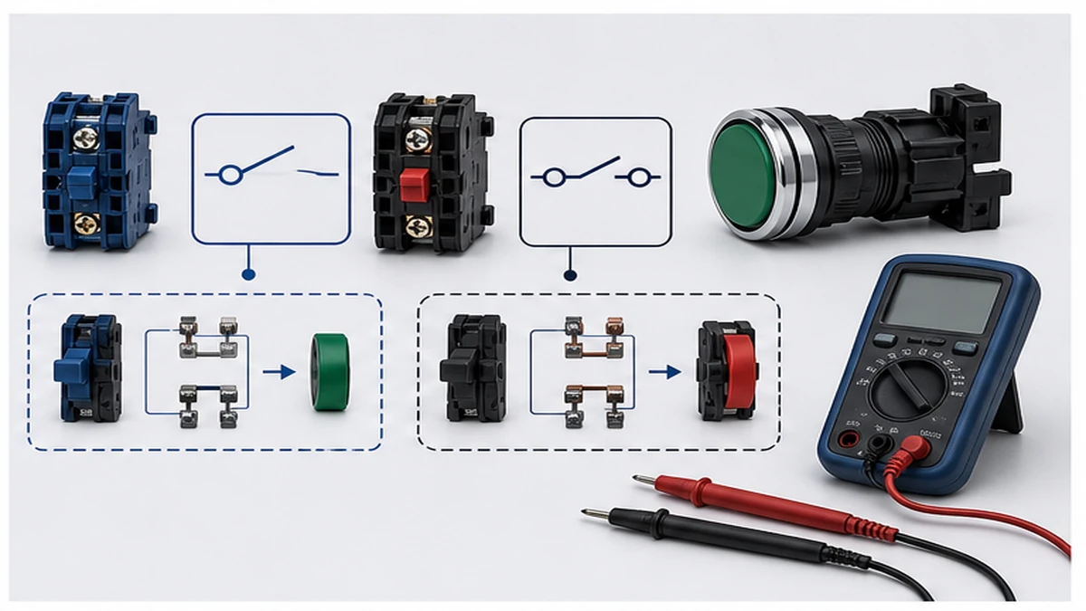
NO contact symbol: Two short parallel lines separated by a visible gap, representing an open circuit in the de-energized state.
NC contact symbol: Two short parallel lines with a diagonal line crossing through them, representing a closed circuit in the de-energized state.
The diagonal line through the NC symbol is the visual cue that the contact is made at rest. Every control schematic drawn to IEC 60617 conventions uses this symbol set, so the contact type can be confirmed from the drawing without referring to the bill of materials.
IEC Terminal Numbering for Push Button Contact Blocks
IEC 60947-5-1 defines a standardized terminal numbering scheme that removes ambiguity from wiring:
NO contact blocks: Terminal pairs 13-14, 23-24, 33-34 for successive blocks in a stacked assembly.
The tens digit identifies the contact block position in the stack, counting from the first block behind the actuator head. The units digit identifies the terminal side within that block: odd numbers are the input side (line side), even numbers are the output side (load side).
A standard 22 mm push button assembled with one NO and one NC block behind a single actuator head exposes four terminals at the rear: 13 and 14 from the NO block, and 11 and 12 from the NC block. If a second NO block is stacked, its terminals are 23 and 24.
Verifying Contact Type Before Wiring
Misreading an NC block as NO — particularly at terminal pair 11-12 — is among the most frequent wiring errors in control panel assembly because the terminal numbers appear similar and the physical blocks can look identical from the front. Before terminating any conductor:
Confirm the schematic symbol type for each terminal pair independently.
Cross-check the symbol against the terminal number — 13/14 must be NO, 11/12 must be NC.
Verify the physical marking on the contact block body against both. Many contact blocks are marked with the symbol directly on the plastic housing.
Use a multimeter in continuity mode at rest to confirm state before wiring — NO blocks give no continuity at rest, NC blocks beep continuously.
This four-step check takes under two minutes per block and prevents the category of errors that produce circuits that power up without tripping a breaker but operate in reverse logic.
For a broader view of how contact configuration interacts with switch types beyond push buttons — including multi-position applications — the push button switch range и SH-B2 push button switch offer contact program tables that follow the same IEC terminal numbering conventions, useful reference when specifying a panel that combines both switch types. For a working explanation of how cam-actuated contacts behave across multiple switch positions, the what is a push button switch technical guide covers cam contact sequencing in detail.
Common NO/NC Wiring Mistakes and How to Prevent Them
Even experienced panel builders encounter NO/NC wiring errors. Because the mistake often produces a circuit that powers up without tripping a breaker, errors can persist undetected until the wrong machine motion occurs or a safety function fails to operate.
The most common errors fall into a predictable set and a systematic checklist resolves the majority before first power-up.
Pre-Wiring Verification Checklist
Before terminating any conductor to a push button contact block:
Confirm contact type from the schematic symbol: NO contacts show a gap between lines; NC contacts show a diagonal through bridged lines. Match the symbol to the circuit function — start commands take NO, stop and E-stop take NC.
Verify terminal numbers: Confirm the conductor routes to the correct terminal number per IEC convention. Do not rely on conductor color alone for contact type identification.
Identify shared common terminals: Some push button assemblies share a common terminal across NO and NC contact blocks. Mis-identifying the common terminal causes one contact type to be permanently active or permanently open regardless of button state.
Confirm utilization category on the datasheet: A contact block marked only as AC-15 is not confirmed for DC-13 circuits. For 24 V DC PLC supply rails or solenoid valve control, the DC-13 rating must appear explicitly in the manufacturer datasheet.
Post-Wiring Continuity Verification Checklist
With all conductors terminated and before applying control voltage:
NO contact, button released: No continuity expected. Continuity at rest means the conductor is wired to an NC terminal.
NC contact, button released: Continuity expected. No continuity at rest means the conductor is wired to an NO terminal, or the contact block itself is open due to damage or misassembly.
Actuated state verification: Press and hold the button while probing. NO blocks must beep. NC blocks must go silent. Both tests must pass before the circuit is considered correctly wired.
Inverted logic behavior check: In a live panel, a load that activates on button release instead of on press is the clearest field indicator of NO/NC reversal. De-energize immediately, re-verify terminal numbering, and correct before re-energizing.
Interlock integrity check: In motor start/stop circuits, accidentally installing two NO contacts where one NC interlock is required eliminates the electrical interlock entirely. A functional test at rated control voltage with the motor disconnected is the reliable method of catching this before commissioning.
For emergency stop circuits where contact reversal creates immediate safety exposure, functional testing at rated control voltage is required before any personnel enter the hazard zone. The contact performance and endurance requirements applicable to push button switches in safety-related control circuits are defined in the IEC 60947-5-1 standard published by the IEC.
Рисунок 4. Полный запрос должен включать номинал, последовательность контактов, монтаж, корпус и требования к документам.
How Shieldhz Confirms NO and NC Contact Configuration for Push Button Orders
Shieldhz is the export brand of Zhejiang Shihe Electric Co., Ltd., founded in 2014 and based in Yueqing, Zhejiang — a region concentrated with low-voltage electrical component manufacturing. The company operates a 5,000+ m2 factory with 100+ employees and 40+ production and testing machines. Products are certified under ISO 9001, CE, RoHS, CCC, CB, TUV, UL, and UKCA where applicable; the applicable certifications for a specific product and destination market are confirmed per model and order rather than assumed as universal.
Specifying the contact configuration for a push button order is not a default selection — it is a required input that determines every downstream wiring and safety outcome in the panel. Shieldhz treats it as a mandatory order parameter, not an assumption.
What Shieldhz Confirms Before Production
When a buyer submits a push button inquiry for the SH-B2 series or other models in the push button range, Shieldhz’s standard process covers the following inputs before confirming the contact program:
Contact configuration: Whether the application requires 1NO, 1NC, or 1NO+1NC per actuator position. If the buyer provides a circuit schematic or panel layout, Shieldhz can verify that the specified contact program matches the drawn circuit logic before production — preventing mismatched logic states such as a 1NC block wired into a start command position.
Rated voltage and current: The operating voltage, rated operational current, and utilization category (AC-15 for AC electromagnetic loads, DC-13 for DC electromagnetic loads) are confirmed against the contact block rating stated in the product datasheet. Buyers specifying 24 V DC PLC rail applications are asked to confirm the DC-13 requirement explicitly.
Actuator type: Momentary (return-to-rest on release) or latching (maintained position) configuration determines the mechanical behavior of the contact block in the circuit. This is confirmed against the application description at the inquiry stage.
IP rating requirement: Standard panel-mount variants and IP67 sealed variants are available in the SH-B2 series; the specific IP class must match the enclosure environment defined in the panel specification. Shieldhz confirms the IP rating against the enclosure ingress protection requirement described by the buyer.
Certification and documentation package: The required certificate type (CE, CCC, UL, CB, UKCA, or combinations) and any supporting documentation requirements — wiring diagrams, dimensional drawings, test reports — are confirmed per order. Buyers procuring for regulated machinery or export markets are advised to specify documentation requirements at the inquiry stage rather than after production.
Wiring diagram and contact table delivery: Shieldhz provides wiring diagrams and contact tables for confirmed configurations as part of the standard documentation package. For multi-button panels requiring both start and stop functions across matched actuator-and-block assemblies, a complete contact program table covering all positions in the panel is available on request.
Panel builders, OEM buyers, and procurement engineers working with the SH-B2 push button switch can submit rated load, pole count, contact combination, utilization category, and enclosure IP requirement to receive a configuration-specific datasheet and quotation. Providing a circuit schematic at the inquiry stage reduces confirmation round-trips and is the recommended practice for multi-position panel orders.
For applications where the switching function extends beyond push buttons to multi-position control — such as source transfer panels or motor direction selection — the GQ metal push button switch и IEC 60947-5-1 push button standard basics follow the same contact program and terminal numbering conventions, allowing a consistent documentation approach across the full panel switch complement.
Часто задаваемые вопросы
What is the difference between a normally open and normally closed push button contact?
A normally open push button contact carries no current at rest and closes the circuit only when the button is pressed. A normally closed push button contact passes current continuously at rest and opens the circuit when pressed. The distinction determines whether the button initiates a circuit action or interrupts one, and it must match the functional requirement of the specific circuit position before any wiring is done.
Why must emergency stop buttons use normally closed contacts?
Wiring an emergency stop button as normally closed means any interruption in the circuit — pressing the button, a severed conductor, a disconnected terminal, or a contact spring failure — results in the circuit opening and the controlled equipment de-energizing. This fail-safe behavior is required by IEC 60204-1 because it ensures the machine cannot remain energized during a wiring fault. An NO emergency stop wired in reverse would leave the machine running if the conductor broke, which is not an acceptable safety outcome.
Can a single push button provide both NO and NC contacts simultaneously?
Yes. Push button assemblies with dual-contact blocks mount both an NO and an NC block behind the same actuator head. A single plunger stroke actuates both blocks at the same time, allowing one push button to close one circuit path and open another in the same press. This is the standard configuration for motor start/stop interlocks and safety door logic where both actions must be mechanically linked.
How do I identify NO and NC terminals on a push button without a schematic?
Set a multimeter to continuity mode and probe each terminal pair with the button fully at rest and unpowered. A pair that gives a continuous beep at rest is a normally closed contact. A pair that gives no signal at rest and beeps only while the button is held down is a normally open contact. After identifying the contact type by test, cross-reference the result against the IEC terminal numbering: 11/12 should be the first NC block, 13/14 should be the first NO block. A mismatch between the test result and the terminal number indicates a wiring error or a non-standard contact block that requires datasheet confirmation.
What IEC standard covers push button contact ratings and performance requirements?
IEC 60947-5-1 is the standard that covers low-voltage control circuit devices and switching elements. It defines rated operational current, making and breaking capacity, mechanical endurance, contact gap requirements, and utilization categories for push button switches used in industrial control panels. This is the primary standard to reference when evaluating contact block performance claims against application requirements.
What does the IEC terminal numbering 13/14 and 11/12 mean on a push button contact block?
These designations follow the terminal numbering system in IEC 60947-5-1. The tens digit identifies the position of the contact block in a stacked assembly — the first block is position 1, giving tens digits of 1 for that position. The units digit identifies which terminal within the block: odd numbers (1 and 3) are the input or line side; even numbers (2 and 4) are the output or load side. Terminal pair 13-14 is therefore the first NO block (tens digit 1 = first position, units 3 and 4 = NO pair). Terminal pair 11-12 is the first NC block (tens digit 1 = first position, units 1 and 2 = NC pair).
What happens if a normally open contact is accidentally wired where a normally closed contact is required?
The circuit behaves in reverse logic. The load will be off at rest and active only while the button is held down, rather than on continuously until the button is pressed. In a motor stop position, this means pressing the stop button does not interrupt the circuit — it momentarily breaks continuity and restores it on release, which has no effect on a latched contactor. In an emergency stop position, this reversal means the machine cannot be de-energized by pressing the E-stop button, which is a direct safety hazard. Any NO/NC reversal in a stop or safety circuit requires immediate correction and a full functional test at rated control voltage before the panel is returned to service.
Ши, Мукси
Ши, Мукси пишет технические статьи Shieldhz для покупателей промышленных систем управления и электрических компонентов, охватывая поворотные кулачковые переключатели, разъединители, PV DC разъединители, кнопки, индикаторные лампы, водонепроницаемые корпуса и клеммные блоки. Статьи основаны на опыте производства и экспорта компании Zhejiang Shihe Electric Co., Ltd., с практическим акцентом на выборе модели, технических характеристиках, чертежах, сертификации, рейтингах IP и деталях запроса, которые покупатели должны подтвердить перед заказом.