العنوان
304 شارع شمال كاردينال 304.
مركز دورشيستر، ماساتشوستس، ماساتشوستس 02124
ساعات العمل
من الاثنين إلى الجمعة: 7 صباحاً - 7 مساءً
عطلة نهاية الأسبوع 10 صباحاً - 5 مساءً
العنوان
304 شارع شمال كاردينال 304.
مركز دورشيستر، ماساتشوستس، ماساتشوستس 02124
ساعات العمل
من الاثنين إلى الجمعة: 7 صباحاً - 7 مساءً
عطلة نهاية الأسبوع 10 صباحاً - 5 مساءً
احصل على المفاتيح الدوارة الممتازة والعوازل ومكونات اللوحة مباشرة من الشركة المصنعة.
املأ النموذج أدناه للحصول على الأسعار والكتالوجات والدعم الفني.
تعرّف على أساسيات مفاتيح عزل الحمل SH30، وفحوصات الاختيار، وسياق الأسلاك، وملاحظات IEC 60947-3، وإرشادات مشتري Shieldhz.
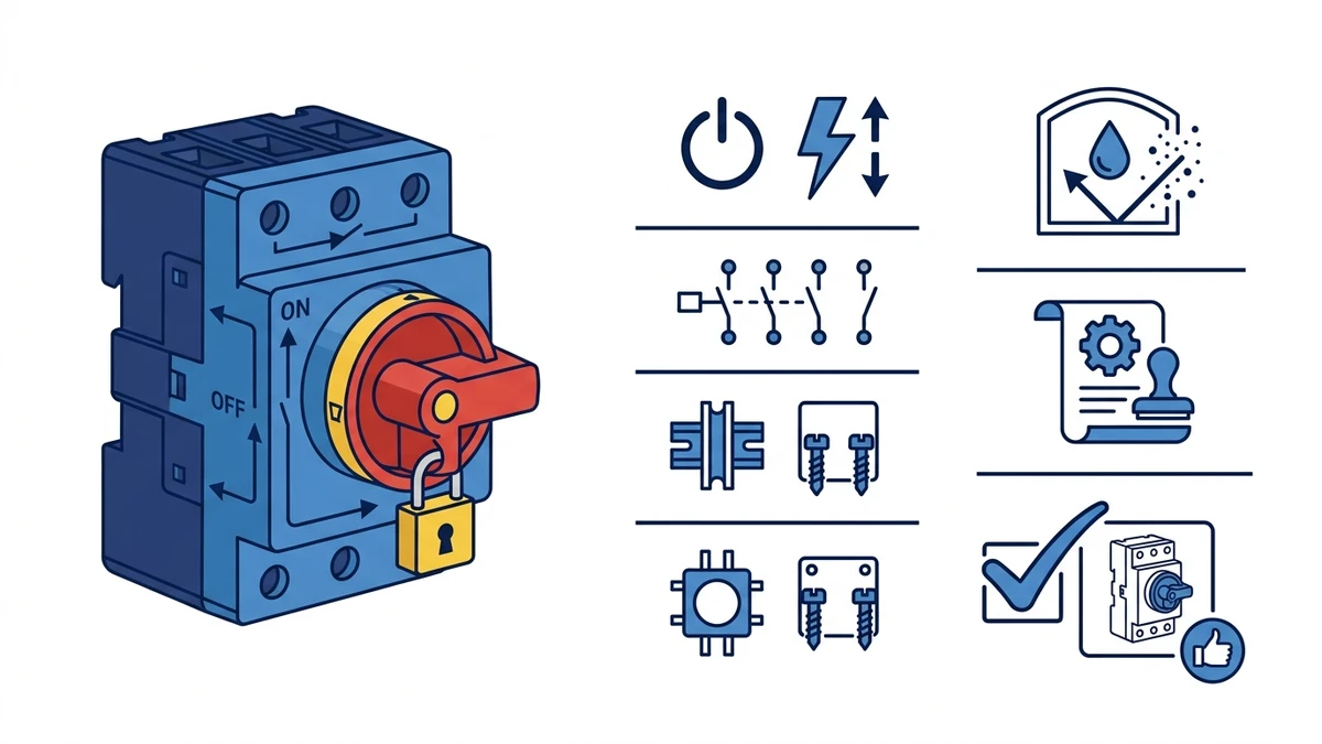
The SH30 load isolator switch is a rotary cam disconnect device positioned by current Shieldhz product information as a 20A to 125A load isolator family, designed to create a verified off-state in HVAC pump circuits and service panels when the selected frame matches the circuit rating. Correctly selected SH30 variants are specified against IEC 60947-3 switch-disconnector requirements, giving maintenance teams a lockable isolation point before accessing downstream wiring or pump components. For panel builders and OEM buyers, the SH30 covers three-phase and single-phase pump motor feeders, uses frame-specific mounting dimensions that should be confirmed before machining, and is available in weatherproof enclosures rated to IP66 for outdoor plant rooms and rooftop installations.
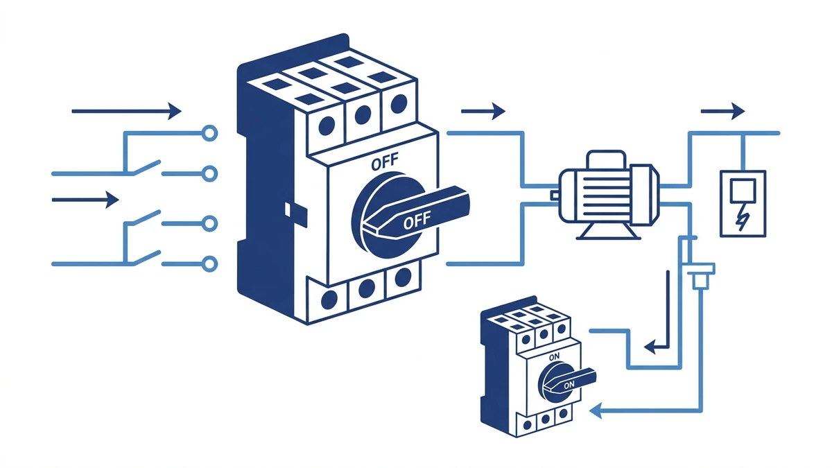
A load isolator switch is a device whose primary job is to create a defined, verifiable off-state — not to protect against overcurrent or short-circuit events. The SH30 achieves this through a cam-driven contact mechanism: rotating the handle through a defined arc, typically 90 degrees, drives silver-alloy contact bridges away from their stationary carriers and opens all poles simultaneously. That simultaneous multi-pole break is what distinguishes a load isolator from a simple on/off switch.
Under IEC 60947-3:2020+AMD1:2025, which applies to switches, disconnectors, switch-disconnectors, and fuse-combination units for distribution and motor circuits with rated voltage up to 1000V AC or 1500V DC, a switch-disconnector must demonstrate rated making and breaking capacity at its utilization category. For inductive motor loads, that means category AC-23A, which governs switching of motor loads including plugging and inching duty. The SH30 series meets this classification, making it suitable for the repetitive start/stop cycles common in HVAC pump applications.
For a broader introduction to how rotary cam switches are classified and applied, see What Is a Load Isolator Switch و What Is a Rotary Cam Switch.
Understanding the internal mechanics explains why the SH30 delivers a reliable, verifiable off-state rather than just an interrupted circuit.
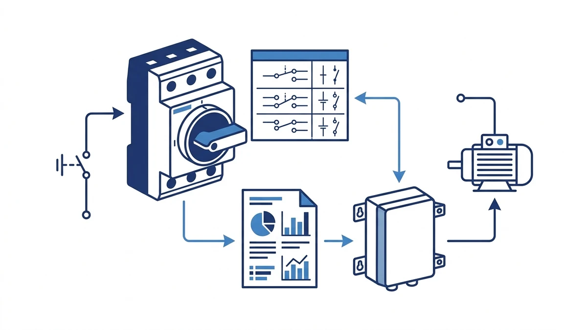
Inside the SH30, the actuator shaft is keyed to a cam disc stack — one disc per pole. Each disc profile is machined so that a defined angular rotation, typically 90 degrees, transitions the contact bridge from a fully closed to a fully open position. The cam surface pushes the spring-loaded contact bridge off the stationary contact pad, breaking the current path. Contact gap at the fully open position is generally 3mm or greater per pole, which satisfies the IEC 60947-3 requirement for a defined off-state in AC utilization category AC-23A.
The contact bridges in the SH30 typically use silver-tin oxide (AgSnO2) or silver-cadmium oxide (AgCdO) alloys. These materials resist welding and erosion during the brief arc that forms at break. In HVAC pump circuits, the load is predominantly inductive — motors present a lagging power factor — so the contact geometry and spring preload are calibrated to quench the arc within the enclosure before it can damage adjacent poles.
AgSnO2 contacts handle higher inrush currents better than AgCdO in modern VFD-fed pump circuits. If your supplier offers a choice of contact alloy, confirm the specification against your datasheet before ordering.
For safe service isolation, all poles must open together. The SH30 cam stack is assembled on a single shaft, so a single handle rotation opens all poles within the same mechanical stroke. This simultaneous action prevents a single-phase condition from persisting on a running motor, which is a recognized cause of winding damage in three-phase pump applications.
The underlying contact mechanics follow the principles documented in the IEC 60947-3 standard, which governs making and breaking capacity, mechanical endurance, and insulation requirements for this class of device.
Commissioning note: In high-vibration environments, verify contact gap with a feeler gauge during commissioning. Cam disc fasteners can back off over time and reduce open-state clearance below the IEC minimum. After any fault event that caused the isolator to break under fault current, inspect contact surfaces before returning the switch to service — arc erosion is not always visible from the outside.
With the contact mechanics established, the next step is translating that isolation capability into a correctly wired installation.
Before connecting any conductors, confirm the SH30 variant matches the circuit: a 3-pole version for three-phase pump motors, or a 2-pole version for single-phase circulation pumps. Incoming supply terminals are labeled L1, L2, L3 (or L1, N for single-phase); outgoing load terminals are labeled T1, T2, T3 (or T1, T2). Conductor cross-section should be sized to the pump’s full-load current — typically 1.5mm2 to 6mm2 for HVAC pump ratings in the 0.37kW to 7.5kW range.
Always cross-check terminal labeling against the SH30 datasheet for your specific variant before wiring. Contact configurations can differ between pole counts and current ratings within the same product family.
Step 1 — Isolate upstream supply. Confirm the upstream circuit breaker or distribution board is locked off before opening the enclosure.
Step 2 — Feed supply conductors into line-side terminals. Insert L1, L2, and L3 into the corresponding incoming terminals and tighten to the manufacturer’s specified torque. For screw-clamp terminals in this frame size, torque is generally in the 1.2 to 2.5 N*m range — confirm against the datasheet for your variant.
Step 3 — Connect load conductors to outgoing terminals. Route T1, T2, and T3 to the pump motor terminal box, maintaining phase sequence to preserve motor rotation direction.
Step 4 — Connect earth continuity. Bond the enclosure earth terminal to the system protective earth (PE) conductor.
Step 5 — Verify conductor seating and IP integrity. Confirm all cable glands are torqued to maintain the enclosure’s ingress protection rating before restoring supply.
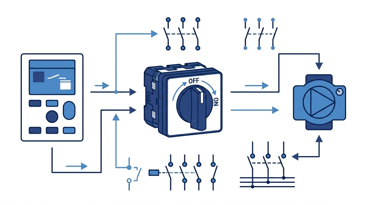
In a typical HVAC plant room installation, the SH30 is mounted within 1 metre of the pump starter or variable speed drive so service personnel can achieve a visible off-state without returning to the main distribution board. This local isolation point is consistent with IEC 60947-3 requirements for disconnectors and switch-disconnectors rated up to 1000V AC.
Wiring field notes:
Choosing the wrong device type is one of the most common specification errors in HVAC panel design. The table below clarifies where each device belongs.
| Criterion | SH30 Rotary Cam Isolator | Fused Isolator | MCB | Contactor-Based Isolation |
|---|---|---|---|---|
| Primary function | Service isolation | Isolation with short-circuit protection | Overcurrent and short-circuit protection | Switching under load; not a true isolator |
| IEC classification | Switch-disconnector (IEC 60947-3) | Switch-disconnector with fuse | Circuit breaker (IEC 60947-2) | Contactor (IEC 60947-4-1) |
| Rated current range | 20A to 125A in current Shieldhz SH30 routes; exact frame controls rating | Frame-dependent; confirm fuse-switch datasheet | Frame-dependent; confirm breaker datasheet | Frame-dependent; confirm contactor datasheet |
| الجهد المقنن | حتى 690 فولت تيار متردد | حتى 690 فولت تيار متردد | Up to 415V AC (standard) | حتى 690 فولت تيار متردد |
| Visible isolation gap | Yes — positive OFF position | نعم | لا يوجد | لا يوجد |
| Fault protection | None — isolation only | Short-circuit via fuse element | Overcurrent and short-circuit | None |
| Lockout/tagout (LOTO) | Yes — padlockable handle | Yes — with fuse carrier | Limited — requires add-on accessory | Not suitable without additional device |
| Maintenance suitability | High — designed for service isolation | Moderate — fuse replacement required | Low — not intended as service isolator | Low — degrades under repeated manual operation |
| Enclosure options | IP65/IP66 weatherproof versions available | Typically IP20 to IP54 | IP20 (DIN rail); IP65 with enclosure | IP20 standard; enclosure required outdoors |
| Typical HVAC application | Pump and fan motor service isolation | Distribution boards with fault protection | Branch circuit protection | Motor starting and stopping under load |
For dedicated service isolation at an HVAC pump, the SH30 is the appropriate choice. Its positive-break mechanism provides a visible, lockable OFF state that satisfies safe isolation requirements without introducing the complexity of fuse management or the contact wear associated with contactor-based switching.
In a typical commercial HVAC installation, the SH30 is positioned downstream of an MCB or fused isolator. The upstream device handles fault protection; the SH30 provides the defined off-state needed for safe maintenance access. This division of function is consistent with IEC 60364-4-46 requirements for devices used to prevent unexpected energization during service work.
For broader rotary cam switch selection across motor control and industrial panel applications, the سلسلة مفاتيح الكامة الدوارة SH30 covers the current and enclosure ratings most commonly specified in HVAC pump circuits. Related cam switch families such as the ل.و.28 و ل.و.42 cover higher pole counts and alternative current ratings for applications outside the standard HVAC pump range.
A correct installation depends as much on sequencing and pre-checks as it does on the physical wiring itself.
Before touching any conductors, confirm the following:
Step 1 — De-energize and lock out the supply. Apply lockout/tagout (LOTO) per your site’s electrical safety procedure before opening the panel.
Step 2 — Mount the switch body. Insert the SH30 through the 30mm cutout from the front face and secure the retaining nut from the rear. Torque to the manufacturer’s specified value to avoid cracking the housing.
Step 3 — Terminate line-side conductors. Connect incoming phase conductors to the upper terminals. Use ferrule-crimped cable ends on flexible conductors. Terminal torque is typically 1.2 to 1.5 N*m for conductors up to 6mm2 — confirm against the datasheet.
Step 4 — Terminate load-side conductors. Connect outgoing conductors to the lower terminals in the same phase sequence.
Step 5 — Verify isolation function. With the panel energized under supervision, rotate the SH30 to the OFF position and confirm zero voltage on the load-side terminals using a calibrated voltage tester.
Step 6 — Label the switch. Mark the isolator with the circuit reference, rated current, and the equipment it serves. Clear labeling is a basic requirement under most national wiring regulations and reduces service errors during future maintenance.
In pump control panels, the SH30 is commonly positioned on the incoming feeder ahead of the motor starter or variable frequency drive, so service teams can create a defined off-state without disturbing the rest of the panel.
For a broader view of compatible rotary cam switch options across different current ratings, the rotary cam switch range covers full specification tables and ordering configurations.
Specifying the right isolator also means confirming it satisfies the layered standards framework that governs both the device and the installation.
| قياسي | Governing Body | What It Covers | Relevant Requirement |
|---|---|---|---|
| IEC 60947-3:2020+AMD1:2025 | IEC | Disconnectors, isolators, and switch-disconnectors for low-voltage circuits | Rated insulation voltage Ui up to 1000V AC; making/breaking capacity at utilization category AC-23A; mechanical endurance per rated cycle count |
| IEC 60529 | IEC | Ingress protection classification for enclosures | Weatherproof HVAC installations typically require IP65 minimum; rooftop or wash-down environments may require IP66 |
| IEC 60364-4-46 | IEC | Isolation and switching requirements for electrical installations | Requires a means of isolation that prevents unexpected energization during service work |
| AS/NZS 3000:2018 | Standards Australia / Standards New Zealand | Wiring rules for electrical installations | Requires a means of isolation within sight of or lockable from the equipment served; isolator must interrupt all active conductors |
IEC 60947-3:2020+AMD1:2025 applies to switches, disconnectors, switch-disconnectors, and fuse-combination units for distribution and motor circuits, with rated voltage up to 1000V AC or 1500V DC. The SH30’s rotary cam mechanism provides a positive off-state with a contact separation gap that satisfies the defined off-state verification requirement under this standard. That physical gap is also what supports lockout/tagout procedures — a padlock on the handle combined with a verified open contact gap gives maintenance teams the dual confirmation required under most site safety management systems.
For service isolation specifically, IEC 60947-3 requires that an isolator achieve a clearance distance of at least 3mm between open contacts at voltages up to 415V AC. The SH30’s cam-driven mechanism delivers this clearance as a function of the disc geometry, not operator technique, which is a meaningful reliability advantage over toggle or lever-type isolators where contact gap can vary with handle position.
For projects in Australia and New Zealand, AS/NZS 3000:2018 requires that the isolation device be within sight of the equipment it serves or be lockable in the open position. The SH30’s padlockable handle satisfies the lockable requirement; its compact form factor makes within-sight installation practical in most plant room layouts.
Confirm certification marks and test reports directly with Shieldhz engineering before finalizing a specification. Datasheet values for contact gap, rated current, and IP rating should be verified against the specific variant and lot, not assumed from the product family designation alone.
For engineers finalizing a specification, the checklist below covers the parameters that matter most. All values should be confirmed against the SH30 datasheet for your specific variant before committing to a bill of materials.
For procurement documentation, request the SH30 test report and declaration of conformity from Shieldhz at the time of order. For OEM buyers integrating the SH30 into a panel assembly, confirm that the switch’s rated PSCC matches the fault level at the point of installation — this is a panel-level calculation, not a device-level assumption.
The full سلسلة مفاتيح الكامة الدوارة SH30 page covers available pole configurations, current ratings, and enclosure options. For applications requiring a different current range or pole configuration, the complete rotary cam switch range provides specification tables across the full Shieldhz cam switch portfolio.
For SH30 inquiries, Shieldhz starts with the load and service environment. The team checks whether the switch is being used for HVAC pump isolation, ventilation equipment, water-pump service points, a GS04-style enclosure route, or a door-interlocked panel application. Current rating, AC duty category, lockable-off requirement, handle visibility, cable entry, enclosure rating, and mounting method are confirmed before model selection.
This matters because an isolator is usually part of a maintenance safety workflow, while overload and short-circuit protection remain the responsibility of the upstream protective device. Buyers should provide the motor or load nameplate, line voltage, enclosure location, expected IP requirement, and required certificate or test-document package. Shieldhz can then align the SH30 variant and documentation with the purchasing and panel-approval process.
A load isolator switch such as the SH30 is designed solely to create a safe, verifiable off-state for maintenance access. It has no built-in fault protection and will not trip on overcurrent or short-circuit events. A circuit breaker is a protective device that trips automatically on overcurrent or short-circuit events but is not classified as a service isolator under IEC 60947-3. In a correctly designed HVAC pump circuit, both devices are present: the circuit breaker upstream for fault protection, the isolator downstream for safe service access.
No. The SH30 provides isolation only and must be paired with an upstream overcurrent protective device such as an MCB or fused isolator. The upstream device handles fault interruption; the SH30 handles safe service isolation downstream. Using an isolator without upstream fault protection leaves the circuit unprotected against short-circuit and overload conditions.
IP rating varies by variant — confirm against the datasheet for your specific SH30 configuration. Weatherproof variants are available rated to IP65 or IP66, making them suitable for outdoor plant rooms, rooftop air handling units, and enclosures subject to directed water jets or heavy condensation. Applications requiring temporary submersion protection would need an IP67-rated enclosure. Do not assume the IP rating from the product family name alone; verify it on the variant datasheet.
Mechanical endurance varies by variant and should be confirmed on the SH30 datasheet for your specific configuration. IEC 60947-3 sets minimum mechanical endurance requirements for switch-disconnectors in this class. For high-duty pump circuits where the isolator is operated frequently, tracking cumulative operations against the rated endurance figure is good maintenance practice and supports planned replacement before end-of-life failure.
Yes. The SH30 handle accepts a padlock in the OFF position, satisfying the physical lockout requirement common to site safety management systems. This padlockable feature, combined with the positive-break contact mechanism that provides a verifiable open-state gap, gives maintenance teams the dual confirmation — physical lock plus electrical verification — required under most safe working procedures for electrical installations.
SH30 terminals typically accept conductors in the 1.5mm2 to 6mm2 range, covering the full-load current requirements of HVAC pump motors from approximately 0.37kW to 7.5kW. Confirm the terminal acceptance range on the datasheet for your specific variant. Flexible conductors should be terminated with ferrule crimps to prevent strand scatter under the terminal screw, which is the most common cause of connection failure at isolator terminals in pump panels.
No. The SH30 is rated for line-frequency switching and is correctly positioned on the line side of a VFD, not the output side. Switching on the VFD output while the drive is running can damage both the drive’s output stage and the isolator contacts. The SH30 should be used to isolate the supply to the drive. If the drive must be isolated from the motor for maintenance, a separate motor-rated isolator on the output side — confirmed as suitable for VFD output switching — is required. Confirm this application with Shieldhz engineering before specifying.
