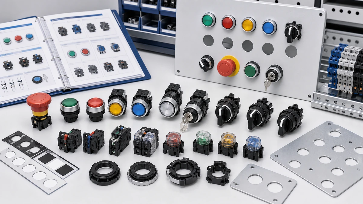
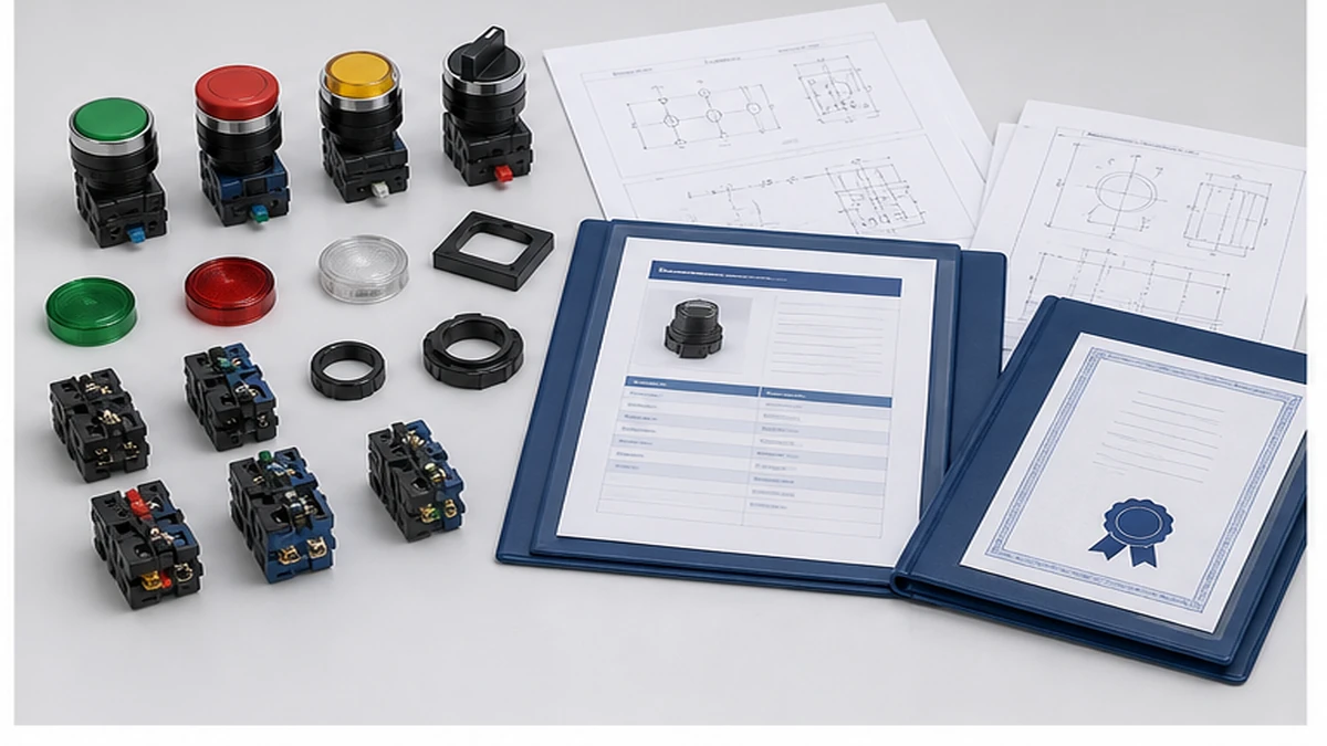
Selecting the right push button switch for an industrial control panel requires confirming four core parameters before specifying any model: operating voltage and utilization category, contact configuration, actuator type, and enclosure IP rating. A mismatch on any one of these parameters causes accelerated contact wear, arc damage, ingress failure, or non-compliance with the applicable control-device standard. This guide walks panel engineers, OEM buyers, and maintenance teams through each decision point in sequence, from electrical ratings and contact block selection through IP requirements, body material, common specification errors, and the documentation package to request before order confirmation.
Specification boundary: Dimensions, contact stack, lamp voltage, IP condition, certification scope, and mounting depth must be confirmed from the current Shieldhz datasheet, drawing, and certificate package for the exact model ordered.
Four Core Selection Parameters
Before specifying a model number, lock down the four parameters that drive every other decision in the selection process.
Operating voltage and utilization category. The contact block must be rated for the actual circuit voltage and load type. the applicable control-device standard defines utilization categories based on whether the switched load is resistive or inductive. AC-15 covers inductive AC loads above 72 VA, such as contactor coils, where inrush current can reach 10 times the sealed current. DC-13 covers inductive DC loads such as solenoids and relays, where arc extinction is more demanding due to the absence of a natural current zero crossing. Specifying an AC-12 rated contact block on an AC-15 inductive circuit accelerates contact erosion and increases arc-welding risk. Always confirm the utilization category against the load type on the circuit diagram, not against the nominal supply voltage alone.
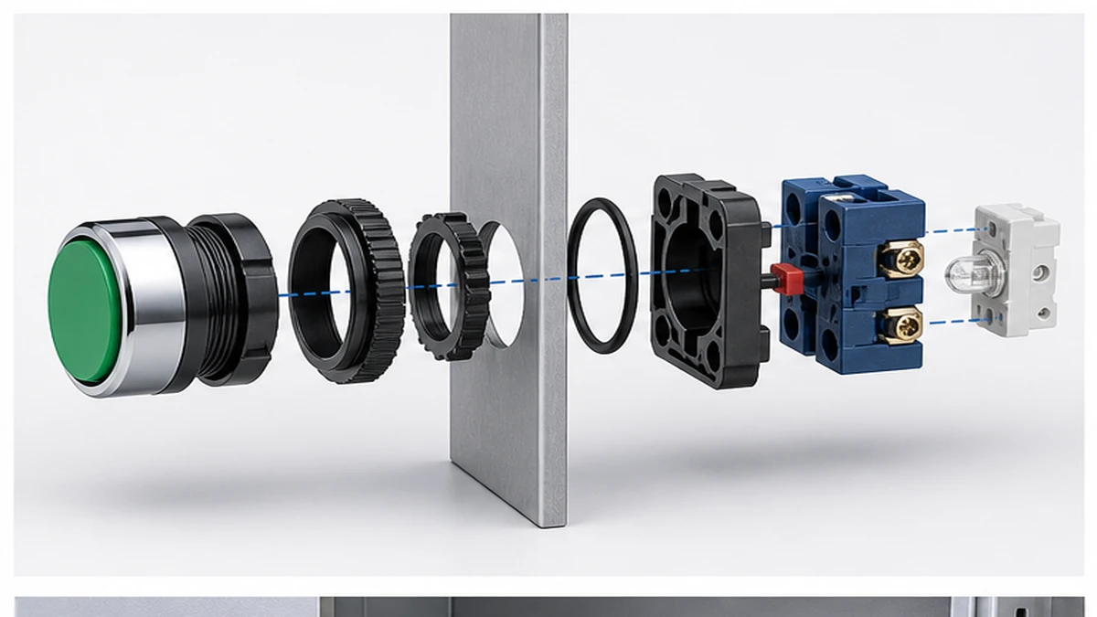
Contact configuration. Specify normally open (NO), normally closed (NC), or changeover contact blocks against the panel wiring diagram before selecting an actuator head. A standard single contact block element provides one NO and one NC output. Most 22 mm frame operators accept up to four stacked blocks, allowing up to two NO and two NC contacts in a single panel cutout. Verify the stacking limit from the dimensional drawing, as exceeding it can stress the mounting bushing and degrade the IP seal at the panel face.
Actuator type. Actuator function defines reset behavior and safety circuit compliance. Momentary spring-return operators are used for start and stop commands. Maintained latching operators hold a selected mode without continuous operator input. Illuminated operators add a pilot LED or lamp module that draws additional load on the auxiliary power circuit, typically 1 to 3 W per indicator, which must be budgeted. Emergency stop operators require a positive-opening NC contact per IEC 60947-5-5, meaning the NC contact opens mechanically regardless of contact welding. A standard spring-return momentary button cannot substitute for an emergency stop function, even temporarily.
Enclosure IP rating. The IP classification per IEC 60529 defines the assembly’s resistance to solid particle and liquid ingress. IP65 is the practical minimum for machine tool and light industrial environments where water jets are possible. IP67 covers brief immersion to one metre. IP69K covers high-pressure steam cleaning cycles in food processing and chemical environments. Rate to the harshest realistic operating condition at the mounting location, not the average condition.
Electrical Ratings in Detail: Ui, Ue, Ie, and Utilization Category
Rated Insulation Voltage versus Rated Operational Voltage
Rated insulation voltage (Ui) defines the dielectric withstand ceiling of the contact assembly and housing. It is not the working voltage. Rated operational voltage (Ue) is the actual circuit voltage the contacts are designed to make and break under load. A contact block carrying Ui 600 V AC with Ue 240 V AC can withstand transient overvoltages at the insulation level but is engineered to switch loads at 240 V. Always confirm both figures from the datasheet and match each against the circuit design. Quoting only Ui when specifying to procurement creates a gap between what is ordered and what is required.
Utilization Category Reference Table
الفئة
Circuit Type
Typical Load
Switching Duty
AC-12
AC resistive or solid-state
Resistive loads, optocouplers
Standard on/off
AC-13
AC solid-state with transformer isolation
Transformer-isolated SSRs
Moderate inrush
AC-14
AC with small electromagnets
Contactors up to 72 VA
Inductive, low VA
AC-15
AC with electromagnets above 72 VA
Solenoids, larger contactors
High inrush
DC-12
DC resistive or solid-state
PLC inputs, pilot lamps
Standard on/off
DC-13
DC with electromagnets
DC solenoids, relays
Inductive, arc risk
Rated operational current (Ie) must always be read together with Ue and utilization category. A contact block rated Ie 10 A at 240 V AC-15 confirms its breaking capacity under inductive load at that specific voltage and category. Reading Ie alone, without Ue and category context, leads to incorrect derating decisions. Verify all three values from the contact block datasheet, not from the actuator head specification.
Impulse Withstand Voltage
Rated impulse withstand voltage (Uimp) defines the contact assembly’s ability to survive transient overvoltages from switching events elsewhere in the panel. the applicable control-device standard requires that Uimp be confirmed relative to the installation overvoltage category. Verify Uimp from the product certificate or test report, not from the catalogue summary.
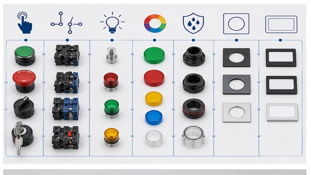
الشكل 2. يجب أن تراعي معايير الاختيار العوامل التالية: حجم المشغل، ونوع التوصيل، والجهد الكهربائي للمصباح، واللون، ومستوى الحماية IP، وفتحة اللوحة، والوثائق المرفقة.
Push Button Switch Types: Momentary, Maintained, Illuminated, and Emergency Stop
Type Classification and Reset Behavior
النوع
Contact Action
Reset Mechanism
Common Application
Momentary NO/NC
Contact closes or opens while depressed only
Spring-return on release
Start/stop commands, signal initiation
Maintained latching
Contact state locks on first press, reverses on second
Manual re-press or key release
Mode selection, hold functions
مُضاء
Momentary or maintained contact with integrated LED
Matches underlying contact type
Status indication, operator feedback
الإيقاف في حالات الطوارئ
Positive-opening NC contact per IEC 60947-5-5
Twist-release, pull-release, or key-release only
Safety circuit interruption, machine stop
The positive-opening action of emergency stop operators is a hard safety requirement, not a preference. IEC 60947-5-5 requires that NC contacts open mechanically regardless of whether the contact has welded. Standard spring-return buttons do not satisfy this requirement and must not be used as substitutes in safety stop circuits.
For illuminated push buttons, confirm whether the LED module is replaceable without disassembling the contact block stack. In environments where maintenance turnaround time matters, a non-replaceable LED module means the entire operator assembly must be swapped for a lamp failure.
For PLC digital input circuits, verify whether the input card expects a momentary pulse or a sustained signal before specifying actuator type. A maintained-contact button wired to a PLC input expecting a pulse creates latent logic faults that are difficult to diagnose during commissioning.
Latching operators used in mode-select circuits should be labeled with both positions on the panel fascia. Unlabeled maintained-contact buttons are a recurring source of operator error during shift handover.
Environmental Requirements: IP Rating, Panel Cutout, and Body Material
IP Rating by Application Environment
Application Environment
Typical Contaminants
Minimum IP Rating
Typical Body Material
Indoor dry control room
Dust, incidental contact
IP40
Thermoplastic PA66
Light industrial / machine tool
Metal dust, coolant splash
IP54
Thermoplastic or zinc alloy
Outdoor or wash-down
Rain, water jets
IP65
Zinc alloy or stainless steel
Food processing / chemical
High-pressure wash, cleaning agents
IP67
Stainless steel 304
Marine / submersion risk
Brief immersion up to 1 m
IP68
Stainless steel 304 or 316
IP ratings are tested on complete assemblies. Mixing an IP67-rated operator body with an unrated or lower-rated contact block stack invalidates the ingress protection claim for the full assembly. Always specify the complete assembly to the required IP level and confirm from the test certificate that the rating applies to the fully assembled configuration, not the body component alone.
Standard Panel Cutout Dimensions
Frame Size
قطع اللوحة
Typical Thread
Panel Thickness Range
16 mm compact
16 mm diameter
M16
Confirm from drawing
22 mm standard
22 mm diameter
M22
Confirm from drawing
30 mm industrial
30 mm diameter
M30
Confirm from drawing
Panel cutout tolerance, typically plus or minus 0.1 mm, must be verified against the product dimensional drawing. An undersized cutout prevents the retaining nut from seating correctly and compromises the IP gasket compression. Confirm minimum and maximum panel thickness from the drawing for each specific series, as these values vary by product family.
Body Material Selection
Zinc alloy die-cast bodies suit general industrial environments where cost and mechanical strength are balanced. Stainless steel grade 304 is used where chemical cleaning cycles occur. Grade 316 is specified where chlorinated washdown water, saline atmosphere, or coastal conditions are present. The molybdenum content in 316 resists pitting corrosion that 304 does not tolerate over extended service. Confirm material grade from the datasheet when the installation environment involves repeated exposure to hypochlorite cleaning solutions or seawater spray.
The IP gasket material, typically silicone or EPDM, must be rated for the ambient temperature range of the enclosure. Compression-set failure of the gasket at sustained elevated temperatures is a documented source of ingress protection loss over time. Confirm gasket material specification from the product datasheet for high-temperature enclosure applications.
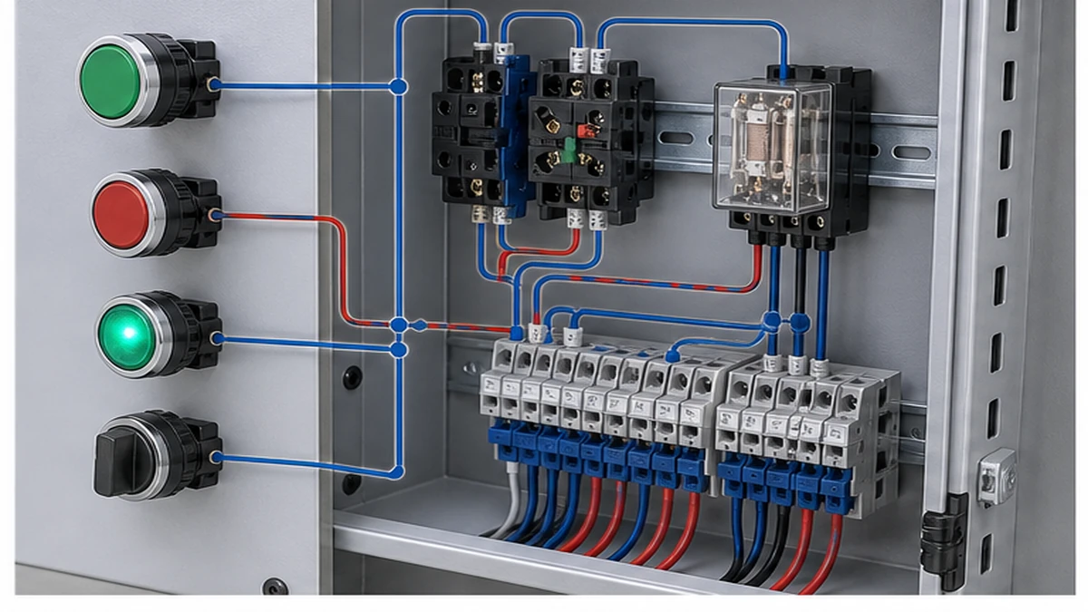
الشكل 3. يجب التحقق من سياق الأسلاك التطبيقية بالمقارنة مع مخطط التلامس الخاص بالشركة المصنعة قبل التنشيط.
How to Specify a Contact Block Configuration: Step-by-Step
Step 1 – Define the operator type. Record actuator function (momentary, maintained, illuminated, emergency stop, or key-operated), mounting cutout diameter, and panel material thickness from the enclosure drawing.
Step 2 – Determine contact block arrangement. Specify the required number of NO and NC contacts. A single block element provides one NO and one NC. Stacking two blocks provides up to two NO and two NC. Confirm the maximum stack count for the selected frame from the dimensional drawing.
Step 3 – Confirm electrical ratings. The contact block must satisfy Ue, Ie, and utilization category for the connected load. For inductive AC control loads, this is typically AC-15. For inductive DC loads, this is DC-13. Verify all three values from the datasheet for the specific contact block model, not the actuator head.
Step 4 – Verify rated insulation voltage. Confirm that Ui on the contact block datasheet meets or exceeds the required margin above Ue for the installation overvoltage category. Most industrial control circuit blocks carry Ui 600 V or 690 V. Confirm the product certificate matches the applicable market standard.
Step 5 – Record terminal type and wire range. Specify screw-clamp or push-in terminals and confirm the accepted conductor cross-section from the datasheet. Control wiring is typically 0.5 mm2 to 2.5 mm2, but verify for the specific block series.
In a standard motor starter panel, the stop command uses a NC contact block wired in series with the contactor coil, and the start command uses a separate NO block. Keeping these in discrete contact elements, rather than sharing a changeover block, makes fault tracing straightforward and simplifies IEC 60204-1 panel wiring documentation.
For reference on related low-voltage switching components, the push button selection reference covers motor circuit isolation and changeover functions that are often specified alongside push button control stations in the same panel. The SH-B2 push button route and GQ metal push button route are common companions to push button stations in motor control and mode-selection circuits.
the applicable control-device standard edition applies to switches, disconnectors, switch-disconnectors, and fuse-combination units for distribution and motor circuits, with rated voltage up to 1000 V AC or 1500 V DC. Where a panel includes both push button control stations and rotary isolation switches in the same circuit, both component types must be evaluated against their respective applicable IEC standards. The full standard text is available through the official IEC control-device publication.
Seven Common Specification Errors and How to Avoid Them
Error 1 – Ignoring utilization category. Specifying an AC-12 rated contact block for an AC-15 inductive contactor coil circuit. Corrective action: confirm the the applicable control-device standard utilization category from the circuit load type before finalizing the model number.
Error 2 – Undersizing contact current rating. Specifying a contact block rated at 3 A for a circuit with 6 A continuous draw. Corrective action: verify Ie at the actual supply voltage and utilization category, and apply a thermal derating margin appropriate to the enclosure ambient temperature.
Error 3 – Mismatching IP rating to installation environment. Installing an IP40 operator in a wash-down zone. Corrective action: map the installation location to IEC 60529 requirements. IP65 is the minimum for liquid jet exposure; IP67 is required where brief immersion is possible.
Error 4 – Overlooking panel cutout tolerance. Ordering a 22 mm body operator for a panel drilled to a 30 mm cutout. Corrective action: confirm body diameter and cutout dimension from the dimensional drawing, not from a catalogue image.
Error 5 – Omitting LED voltage compatibility. Specifying a 24 V DC LED module for a 230 V AC control circuit. Corrective action: cross-check pilot light supply voltage against the control transformer secondary on the wiring diagram before confirming the order.
Error 6 – Confusing momentary and maintained action. Wiring a latching maintained-contact operator where a momentary NO pulse is required by a PLC digital input. Corrective action: define the required actuation logic in the component specification and confirm it matches the input card’s signal expectation before ordering.
Error 7 – Accepting an incomplete documentation package. Proceeding to order without verifying CE Declaration of Conformity, contact block datasheet, IP test certificate, and wiring diagram. Corrective action: request model-specific documents, not product-family summaries, and confirm they reference the exact model number being ordered.
الشكل 4. يجب أن يتضمن الاستفسار الكامل التصنيف وتسلسل التلامس والتركيب والحاوية ومتطلبات المستند.
How Shieldhz Confirms Your Push Button Switch Specification Before Shipment
Shieldhz is the export brand of Zhejiang Shihe Electric Co., Ltd., established in 2014 in the Yueqing electrical manufacturing cluster in Zhejiang Province. The manufacturing facility covers more than 5,000 m2 and operates with over 100 employees and 40 or more production machines. Applicable certifications include ISO 9001, CE, RoHS, TUV, UL, UKCA, CCC, and CB, with applicability depending on the specific product series and destination market.
For every push button switch inquiry, the Shieldhz engineering team runs a structured specification confirmation process before generating a quotation or releasing an order to production. This process is designed to prevent the seven common errors described above from reaching the panel build stage.
Circuit parameter review. The team confirms operating voltage, rated operational current, AC or DC load type, and utilization category against the applicable control-device standard requirements. Where the buyer submits a circuit diagram or motor nameplate data, the team maps the contact block rating to the actual switching duty rather than relying on nominal panel voltage alone.
Mechanical and operator type confirmation. Mounting cutout diameter, actuator head type, contact block stack count, and required NO/NC configuration are verified against the panel layout drawing or enclosure specification. Where maximum stack depth is a constraint, the team identifies the correct frame before order entry.
Environmental rating check. The required IP class per IEC 60529, the ambient temperature range, and the enclosure body material are confirmed against the installation environment. For food processing or chemical applications, the team checks gasket material compatibility with the specified cleaning agents before confirming the variant.
Documentation package preparation. Each confirmed order is supported by the applicable CE Declaration of Conformity, product datasheet with Ui, Ue, Ie, and utilization category stated for the specific model, dimensional drawing with panel cutout and thickness range, and IP test certificate referencing the complete assembly. For North American projects, UL 508 listing evidence is provided where applicable to the ordered series.
LED and indicator cross-check. For orders combining illuminated push button operators with the panel control circuit supply, the LED module voltage rating is verified against the control transformer secondary before shipment to prevent the flickering and premature failure issues described in the FAQ section below.
Buyers can initiate the specification review by submitting operating voltage, rated current, utilization category, required IP rating, contact configuration, panel cutout dimension, actuator type and color, required certificates, and order quantity through the product enquiry page. The selector switch reference is available for panels that require rotary isolation or changeover functions alongside the push button control station in the same assembly.
الأسئلة الشائعة
What is the difference between AC-15 and DC-13 utilization categories?
AC-15 covers switching of inductive AC loads above 72 VA, such as contactor coils, where inrush current can reach 10 times the sealed current. Arc extinction occurs naturally at each voltage zero crossing. DC-13 covers inductive DC loads such as solenoids and relays. Because DC circuits have no natural current zero crossing, arc extinction is more demanding and contact ratings at equivalent voltages are typically lower than for AC-15. Always confirm which category applies from the load type on the circuit diagram, not from the supply voltage classification.
How do I select the correct IP rating for a push button switch installation?
Match the second IP digit to the worst-case liquid exposure at the mounting location. IP65 covers sustained water jets from any direction. IP67 covers temporary immersion to one metre for up to 30 minutes. IP69K covers high-pressure, high-temperature steam cleaning at close range. The first digit should be 6 for any environment where total dust exclusion is required. Rate to the harshest condition that will occur during normal operation or cleaning cycles. Note that IP ratings apply to the complete tested assembly. A body rated IP67 paired with a contact block rated IP40 produces an assembly rated to the lower value.
Can I stack multiple contact blocks on a single push button operator?
Most 22 mm frame operators accept up to four stacked contact blocks, providing combinations of NO and NC contacts without additional panel cutouts. Confirm the maximum stack depth and total block weight from the dimensional drawing for the specific series. Excessive stacking can apply bending stress to the mounting bushing and reduce gasket compression at the panel face, degrading the IP seal over time. Where a high contact count is required in a compact cutout, confirm with the manufacturer that the specified stack configuration has been validated as an assembly.
What certifications should I request before accepting a push button switch for a panel build?
At minimum, request an the applicable control-device standard test report referencing the specific contact block model number, a CE Declaration of Conformity for European market projects, and UL 508 listing evidence for North American installations. An IP test certificate per IEC 60529 is required wherever the ingress protection rating is a compliance condition of the panel certification. All documents should reference the exact model number ordered, not a product family or range designation. If any document covers a broader family, ask for model-specific confirmation in writing before finalizing the purchase order.
Why does an illuminated push button flicker when connected to a PLC transistor output?
Flickering typically results from one of two causes. The LED module’s minimum holding current exceeds what the PLC transistor output can sustain, particularly at low duty cycles or when the output is in its off-state with residual leakage current. Alternatively, the LED module supply voltage does not match the control circuit voltage, creating a current imbalance through the module. Verify that the LED module voltage rating matches the control transformer secondary voltage. If the PLC output’s leakage current is insufficient to prevent false illumination or flickering, a parallel bleeder resistor sized for the output card’s leakage specification will stabilize the circuit.
What panel cutout size is standard for general industrial control panels?
The 22 mm cutout diameter is the most widely used format for general industrial control panels. It balances compact panel space usage with a robust M22 mounting thread and broad availability across momentary, maintained, illuminated, and emergency stop actuator types. The 30 mm format is used where larger actuator heads are required for gloved-hand operation, high-visibility emergency stop applications, or heavy-duty industrial environments where a more substantial mounting footprint is mechanically appropriate. The 16 mm format is used in space-constrained panels where the lower current and stack depth limits of the smaller frame are acceptable for the application.
How do I verify that a supplier’s documentation package is complete before placing an order?
The complete documentation package for a push button switch order should include the product datasheet explicitly stating Ui, Ue, Ie, and utilization category for the specific contact block model; a dimensional drawing confirming panel cutout diameter, panel thickness range, and maximum stack depth; the applicable conformity declaration referencing the model number; and an IP test certificate covering the fully assembled configuration. If any document refers to a product family rather than the specific model number, request model-specific confirmation before committing to the purchase order. For projects with multiple certification requirements across markets, confirm which certificates apply to each destination before order entry rather than after delivery.
شي، موكسي
يكتب شي، موكسي مقالات شيلدهز الفنية لمشتري التحكم الصناعي والمكونات الكهربائية، والتي تغطي مفاتيح الكامات الدوارة، ومفاتيح العازل، ومفاتيح فصل التيار المستمر الكهروضوئية، وأزرار الضغط، وأضواء المؤشر، والحاويات المقاومة للماء، والكتل الطرفية. تستند المقالات على خبرة شركة Zhejiang Shihe Electric Co., Ltd. في التصنيع والتصدير، مع التركيز العملي على اختيار الطراز وأوراق البيانات والرسومات والشهادات وتصنيفات IP وتفاصيل الاستفسار التي يجب على المشترين التأكد منها قبل الطلب.