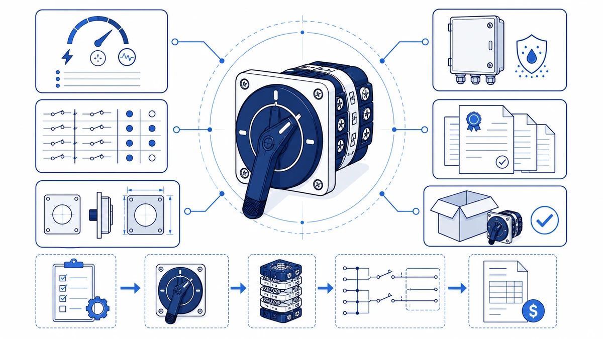
لطلب مخطط أسلاك تم التحقق منه وعرض أسعار تنافسي لمفتاح كاميرا دوارة، تحتاج إلى خمسة مدخلات مؤكدة قبل الاتصال بأي مورد: جهد التشغيل، والتيار المقنن، وعدد الأقطاب، وتسلسل الموضع، وتصنيف IP للحاوية. تحدد هذه المعلمات رمز طراز مفتاح الكامة الدوارة القابل للبناء وتسمح لفريق هندسي بإرجاع مخطط أسلاك مطابق وجدول الاتصال وعرض أسعار رسمي في رد واحد. عادةً ما يؤدي تخطي أي من هذه المدخلات إلى تشغيل جولة واحدة على الأقل من رسائل البريد الإلكتروني التوضيحية، مما يؤخر كلاً من الرسم التخطيطي والسعر. يشرح هذا الدليل كيفية جمع هذه المدخلات، وفك شفرة رمز نموذج موجود، وقراءة جدول جهات الاتصال، وإرسال استفسار كامل إلى Shieldhz.
ما هي المعلومات التي يجب جمعها قبل طلب رمز النموذج وعرض الأسعار
قبل فتح استفسار، تأكد من المعلمات الخمس التي تحرك كل حقل من حقول رمز النموذج. إن سحبها من المستندات المصدر بدلاً من الذاكرة يمنع أكثر التأخيرات الشائعة في الاقتباس.
جهد التشغيل والتيار المقدر
المعلمتان الكهربائيتان الأكثر أهمية هما الجهد التشغيلي المقنن والتيار المقننن. بالنسبة لمفاتيح التبديل الاختيارية متعددة المواضع المتوافقة مع IEC، يمكن أن يصل جهد العزل المقنن (Ui) إلى 690 فولت تيار متردد اعتمادًا على تصميم السلسلة وحامل التلامس. تتراوح الإطارات الحالية عبر خطوط مفاتيح التبديل الاختيارية الصناعية الشائعة من 10 أمبير إلى 63 أمبير. اقرأ كلا القيمتين من لوحة اسم المحرك أو مخطط دائرة اللوحة بدلاً من أرقام الأحمال المقدرة، لأن فئة الاستخدام تعتمد على ما إذا كان المفتاح يقوم بعمل وفصل الأحمال المقاومة أو المختلطة أو الأحمال الحركية.
IEC 60947-3:2020+AMD1:2025 ينطبق على المفاتيح، والمفصلات، ومفصلات المفاتيح، ومفصلات المفاتيح، ووحدات دمج الصمامات لدوائر التوزيع والدوائر الحركية ذات الجهد المقنن حتى 1000 فولت تيار متردد أو 1500 فولت تيار مستمر. التأكد من أن المفتاح الخاص بك يقع ضمن هذا النطاق هو نقطة التحقق الأولى من الامتثال قبل اختيار الإطار.
تسلسل الموضع وعدد الأعمدة
يتم تعريف برنامج تلامس مفتاح الكامة الدوارة من خلال عدد مواضع التبديل التي يوفرها وعدد الأقطاب التي يتم تعشيقها في كل موضع. بالنسبة لتطبيقات عكس المحرك أو تطبيقات بدء تشغيل دلتا النجوم، يجب أن يتطابق برنامج التلامس مع مخطط الدائرة تمامًا. قم بتأكيد عدد المواضع، والخطوة الزاوية بين المفاتيح (عادةً 45 درجة أو 90 درجة حسب السلسلة)، وما إذا كان إجراء العودة الزنبركية مطلوبًا. لا يمكن تصحيح المفتاح الذي تم طلبه بعدد مواضع خاطئ أو خطوة زاوية غير صحيحة في الميدان دون استبدال كامل.
فئة الاستخدام
اذكر فئة الاستخدام بشكل صريح بدلاً من وصف الحمل بلغة بسيطة. يغطي AC-21A الأحمال المقاومة والحثية قليلاً مع تيار زائد معتدل. AC-22A يغطي الأحمال المختلطة المقاومة والاستقرائية. يغطي AC-23A تبديل محرك القفص السنجابي، حيث يمكن أن يصل تيار الصنع إلى ستة إلى ثمانية أضعاف تيار التشغيل المقدر. تضمن تسمية الاستفسار بالفئة الصحيحة أن مادة التلامس وهندسة تبريد القوس الكهربائي تتناسب مع مهمة التحويل الفعلية، وليس فقط تيار الحالة المستقرة.
متطلبات الضميمة والشهادة
حدد تصنيف IP المطلوب قبل الاختيار بين إطار تركيب اللوحة القياسي والتكوين المقاوم للعوامل الجوية. بالنسبة للبيئات الخارجية أو بيئات الغسيل، فإن IP65 هو الحد الأدنى من المتطلبات الشائعة؛ تتطلب التركيبات المعرضة للغمر المؤقت IP67 أو IP68 وفقًا للمواصفة IEC 60529. لاحظ أي شهادات سوق مطلوبة - CE أو CCC أو RoHS أو معادلة UL أو تقارير اختبار TUV - لأن توفر الشهادة يؤثر على حزمة الوثائق وفي بعض الحالات يؤثر على مسار الإنتاج.
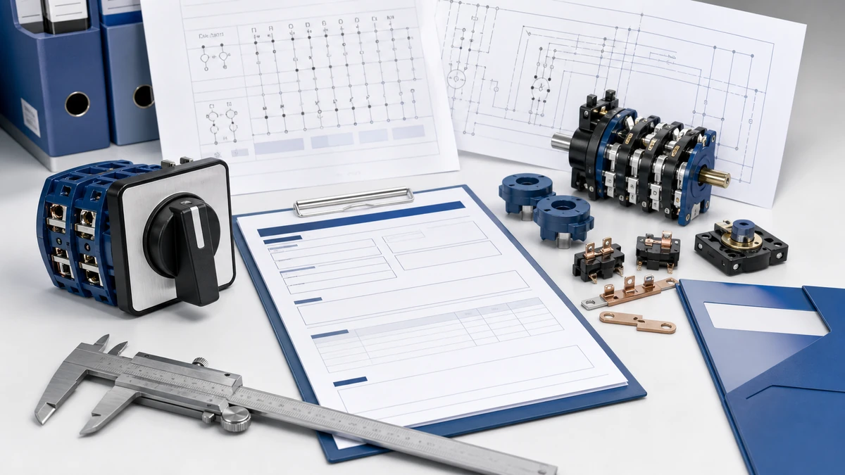
الشكل 1. المفهوم الأساسي وراء اختيار رمز نموذج مفتاح الكامة الدوارة.
كيف يتم هيكلة رموز طراز مفتاح الكاميرا الدوارة
مع تأكيد معلمات الإدخال الخمسة، يمكنك فك تشفير رمز لوحة اسم موجودة أو إنشاء رمز جديد. رمز النموذج هو سلسلة مواصفات مضغوطة تقوم بترميز كل معلمة قابلة للتكوين في مرجع واحد. ينتج عن القراءة الخاطئة لحقل واحد مفتاح بتسلسل تلامس خاطئ أو عدد أقطاب خاطئ، وهذا هو السبب في أن معرفة رمز النموذج مهم أثناء عملية شراء بديل كما هو مهم أثناء التصميم الأولي للوحة.
معرّف السلسلة
تحدد الأحرف الافتتاحية عائلة المنتج والإطار الميكانيكي. وتحدد الأحرف سلسلة LW28 و سلسلة LW42 هما عائلتان مختلفتان مع اختلاف هندسة الكامة وأبعاد حامل التلامس ومتطلبات قطع اللوحة. يمكن أن يؤدي استبدال أحد الإطارين بالآخر دون التحقق من رسم التركيب إلى إبطال الملاءمة في لوحة تحكم موجودة حتى إذا كانت التصنيفات الكهربائية تبدو متطابقة.
مجال التصنيف الحالي
مباشرةً بعد بادئة السلسلة، يوجد حقل رقمي يحدد التيار التشغيلي المقدر بالأمبير. يعد التأكد من هذا الحقل مقابل لوحة اسم المحرك أو جدول الحمل هو الخطوة التشخيصية الأولى عند الاشتباه في أن مفتاح الاستبدال أقل من التقدير. لا تستبدل إطارًا أقل تقييمًا لمجرد أنه يناسب نفس فتحة اللوحة.
رمز برنامج الاتصال والوظيفة
يحدد هذا الحقل عدد مواضع التبديل والحالة المفتوحة أو المغلقة لكل جهة اتصال في كل خطوة كاميرا. في ممارسة الصيانة، يتم إنشاء مخطط الأسلاك مباشرةً من هذا الرمز - كل عمود موضع يعيِّن زاوية كامة مميزة. يعد عدم التطابق بين برنامج التلامس المثبت ورسم الدائرة أحد المصادر الأكثر شيوعًا لأعطال دائرة التحكم في بادئات المحركات متعددة المواضع. عند فك ترميز لوحة اسم في الحقل، عادةً ما يكون الجزء من الكود الذي يلي الشرطة المائلة هو الحقل الأكثر فائدة من الناحية التشخيصية؛ تأكد منه أولاً قبل طلب مخطط بديل.
عدد الأعمدة والخيارات الإضافية
تشير الحقول النهائية إلى عدد الأعمدة وأي تلامس إضافي أو متغير الضميمة. بالنسبة للتطبيقات الخارجية، تميّز لاحقة تصنيف IP الوحدة المثبتة على اللوحة عن المجموعة المقاومة للعوامل الجوية. تصفح مجموعة مفاتيح الكامات الدوارة الكاملة لمراجعة السلسلة وعدد الأعمدة وخيارات الضميمة قبل تقديم طلب عرض أسعار.
كيفية قراءة جدول جهات الاتصال وطلب مخطط الأسلاك الصحيح
قراءة مخطط أسلاك مفتاح الكاميرا الدوارة بشكل صحيح هي الخطوة الأولى في استكشاف أعطال التلامس وإصلاحها، والتحقق من توافق الاستبدال، وتشغيل لوحة مفاتيح جديدة متعددة المواضع.
الخطوة 1: تحديد موقع رمز النموذج وفك تشفيره
ابحث عن رمز الطراز على لوحة اسم المفتاح أو وثائق الشراء الأصلية. يتم تعيين كل جزء من الأحرف إلى معلمة محددة. إذا كانت لوحة الاسم غير مقروءة بسبب التلف الناتج عن الحرارة، قم بتصوير تسلسل طبقات قرص الكامة مباشرةً: عدد طبقات قرص الكامة يساوي عدد الأعمدة، وتحدد هندسة الفص على كل قرص عائلة برنامج التلامس. تعامل مع التكوين المادي للكامات على أنه الحقيقة الأساسية كلما اختلفت لوحة الاسم ومخطط الدائرة، خاصةً بعد تحديث اللوحة حيث قد تكون إعادة التسمية قد حدثت.
الخطوة 2: تفسير جدول جهات الاتصال
إن جدول التلامس هو جوهر أي مخطط أسلاك مفتاح كاميرا. يمثل كل صف زوج تلامس واحد؛ ويمثل كل عمود موضع مفتاح تبديل واحد. تشير الخلية المملوءة إلى أن التلامس مغلق في ذلك الموضع؛ وتشير الخلية الفارغة إلى أنه مفتوح. عند استكشاف الأعطال وإصلاحها، قارن نتائج الاستمرارية المقاسة بالجدول بشكل منتظم، واختبر كل زوج تلامس في كل موضع باستخدام مقياس أومتر منخفض المقاومة. يشير الانحراف عند موضع واحد محدد عادةً إلى تآكل الكامة أو تآكل الزنبرك أو أكسدة التلامس المحصورة في تلك الطبقة بدلاً من وجود عطل منهجي عبر الوحدة.
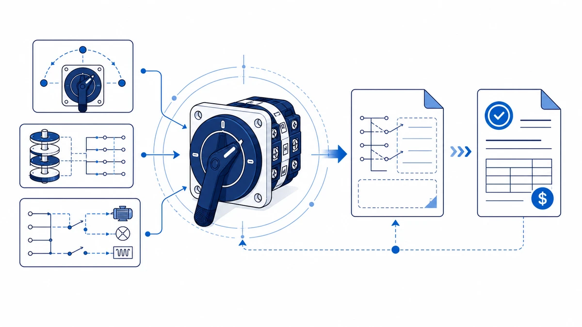
الشكل 2. يجب أن تربط فحوصات الاختيار وظيفة المفتاح، والتصنيف، وتسلسل التلامس، ومسار التركيب، والوثائق.
الخطوة 3: طلب الرسم البياني الصحيح
عند الاتصال بالمورد الخاص بك، قدم كل ما يلي للحصول على مخطط أسلاك تم التحقق منه في رد واحد:
الرمز الكامل للطراز من لوحة الاسم أو أعيد بناؤه من الفحص المادي
عدد المواضع وتسلسل التبديل، على سبيل المثال تسلسل من 3 مواضع تحمل الأرقام 0 وI وII
الجهد والتيار المقدران، على سبيل المثال 20 أمبير عند 380 فولت تيار متردد
نوع التطبيق: عكس اتجاه المحرك، أو الاختيار، أو العازل، أو التحويل
ما إذا كان رسم قطع اللوحة أو وثائق التوافق مع المواصفة IEC 60947-3 مطلوبة إلى جانب الرسم التخطيطي
بالنسبة إلى LW42 أو سلسلة SH30 يؤدي تحديد متطلبات التوثيق في نقطة الاتصال الأولى إلى تجنب دورة الطلب الثانية وتسريع جدولة الصيانة.
خطوة بخطوة: تقديم استفسار عن تبديل الكاميرات الذي يحصل على استجابة سريعة ودقيقة
يزيل الاستفسار الكامل من جهة الاتصال الأولى المصدر الأكثر شيوعًا للتأخير في عرض الأسعار. تقوم الخطوات الخمس أدناه بتعيين كل مدخل من المدخلات إلى الحقل الذي يؤثر عليه في رمز النموذج وحزمة الوثائق.
الخطوة 1: تحديد سلسلة المحول وحجم الإطار
تأكد من عائلة المنتجات التي تنطبق على لوحتك. تغطي السلسلة LW28 قواطع اللوحة المدمجة ومهام مفاتيح الاختيار العامة متعددة المواضع. تتعامل السلسلة LW42 مع تطبيقات التحكم في المحركات الصناعية ذات التيار العالي مع إطار حامل تلامس أكبر. قم بتضمين العدد المطلوب من المواضع ونوع مقبض التشغيل، مثل مقبض المسدس أو المقبض أو المشغل الذي يعمل بالمفتاح، لأن نوع المقبض يؤثر على أبعاد التركيب وأحكام القفل.
الخطوة 2: تحديد المعلمات الكهربائية
اذكر الجهد التشغيلي المقدر ونوع الحمل وفئة الاستخدام. بالنسبة للتحكم في محرك التيار المتردد، تأكد ما إذا كان الحمل يندرج تحت AC-21A أو AC-22A أو AC-23A كما هو محدد في المواصفة IEC 60947-3:2020+AMD1:2025. قم بتضمين التيار المقنن بالأمبير وجهد العزل المقننن Ui لتأكيد تنسيق العزل مع بقية مجموعة اللوحة.
الخطوة 3: تحديد برنامج الاتصال
قم بإرفاق أو وصف تسلسل تبديل التلامس المطلوب لكل موضع كاميرا. تتيح الشبكة التي توضح الأعمدة التي يتم إغلاقها في كل موضع زاوي - على سبيل المثال 0 درجة، 45 درجة، 90 درجة - للفريق الهندسي مطابقة ملف تعريف كامات موجود أو وضع علامة على متطلبات برنامج اتصال مخصص على الفور. يستغرق الرسم التخطيطي أقل من دقيقتين لإعداده ويحل محل عدة جولات من الوصف المكتوب الذي يصعب التحقق منه بدون رؤية مرئية.
الخطوة 4: تأكيد البيئة واحتياجات التوثيق
حدد تصنيف IP المطلوب ومجموعة الشهادات أو تقارير الاختبار المطلوبة للسوق الخاص بك. تشمل المتطلبات الشائعة إعلان المطابقة CE، أو بيان الامتثال لـ RoHS، أو شهادة CCC للسوق الصينية، أو تقرير اختبار من طرف ثالث. ويسمح ذكر هذه المتطلبات مقدمًا للفريق الهندسي بتأكيد توافرها قبل إصدار عرض الأسعار وليس بعد تقديم الطلب.
الخطوة 5: الإرسال عبر قناة الاستفسارات الفنية
إرسال المواصفات المجمعة - السلسلة، والمواضع، والتصنيف الحالي، وجدول التلامس، ومتطلبات IP، وقائمة الوثائق - من خلال صفحة التواصل مع شيلدهز. أرفق أي مخططات أسلاك موجودة، أو صور فوتوغرافية للوحة الاسم، أو أوراق بيانات المحرك. تسمح الطلبات التي تحتوي على بيانات كاملة مقدمة في هذه المرحلة للفريق الهندسي بإرجاع رمز الطراز المؤكد ومخطط الأسلاك وعرض الأسعار في رد واحد بدلاً من تبادل عدة رسائل.
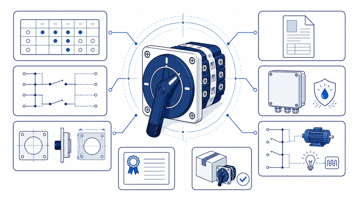
الشكل 3. يجب التحقق من سياق الأسلاك التطبيقية بالمقارنة مع مخطط التلامس الخاص بالشركة المصنعة قبل التنشيط.
كيف يؤكد شيلدهز على رمز النموذج والمخطط وحزمة الوثائق الخاصة بك
Shieldhz هي العلامة التجارية التصديرية لشركة Zhejiang Shihe Electric Co. المحدودة، التي تأسست في عام 2014 وتعمل من منشأة تزيد مساحتها عن 5000 متر مربع في يويتشينغ في تشجيانغ، تشجيانغ، ويعمل بها أكثر من 100 موظف و40 آلة إنتاج. الشركة حاصلة على شهادة إدارة الجودة ISO 9001 وتقوم بتصدير منتجات تحمل وثائق CE و RoHS و TUV و UL و UKCA و CCC و CB حسب الطراز والسوق المقصود.
بمجرد استلام الاستفسار الكامل، يضمن تسلسل التأكيد الداخلي المنظم محاذاة رمز النموذج النهائي ومخطط الأسلاك وحزمة الوثائق قبل بدء الإنتاج أو الشحن. يساعد فهم كل مرحلة المشترين على توقع التوقيت وتجنب التأخير الناجم عن المواصفات غير المكتملة.
فحص الاستفسار والتحقق من صحة المدخلات
تبدأ العملية عندما يقدم المشتري المدخلات الفنية. وكحد أدنى، يجب أن يتضمن الاستفسار جهد التشغيل، والتيار المقنن، وعدد المواضع، وعدد الأعمدة، وفئة الاستخدام، ومتطلبات تصنيف IP للحاوية، والشهادات المطلوبة. بالنسبة للتكوينات المعقدة متعددة المواضع، يقلل رسم تخطيطي لبرنامج التلامس أو مخطط الدائرة الكهربائية الحالي بشكل كبير من دورة المراجعة. يقوم الفريق الهندسي بوضع علامة على أي مدخلات تقع خارج نطاق برنامج التلامس القياسي قبل مرحلة تأكيد رمز النموذج.
التحقق من كود النموذج وفحص قابلية البناء
يقوم الفريق التقني بمقارنة المعلمات المقدمة مع جداول تلامس سلسلة مفاتيح الكامات للتأكد مما إذا كان تسلسل الموضع المطلوب يمكن تحقيقه ضمن حدود القطب وبرنامج التلامس للإطار المحدد. يتم التحقق من جهد العزل المقنن Ui وجهد الصمود الدفعي المقننن Uimp مقابل جهد نظام المشتري. إذا كانت التهيئة المطلوبة تقع خارج البرنامج القياسي، يحدد الفريق أقرب متغير قابل للبناء أو يحدد متطلبات كاميرا مخصصة مع مهلة إضافية تقديرية.
مخطط الأسلاك وتأكيد حزمة الأسلاك والرسم البياني
بمجرد التحقق من صحة رمز النموذج، يتم إعداد رسم تخطيطي للأسلاك مطابق لبرنامج التلامس المحدد هذا إلى جانب رسم قطع اللوحة وصحيفة أبعاد التركيب. بالنسبة لسلسلة LW42 أو غيرها من مفاتيح التبديل ذات الإطار الأكبر، تتضمن حزمة الوثائق جدولاً لموضع التلامس يوضح حالات الفتح والإغلاق في جميع مواضع التبديل. وتستخدم فرق الصيانة هذا الجدول مباشرةً أثناء استكشاف الأعطال وإصلاحها وتشغيل الاستبدال دون الحاجة إلى الاتصال بالمورِّد مرة أخرى.
إصدار عرض الأسعار مع مرجع التوثيق
يشير عرض الأسعار المؤكد إلى سلسلة رمز الطراز الدقيق، ومراجعة الرسم، والشهادات المعمول بها، والمهلة الزمنية. يعتمد توقيت التأكيد على اكتمال البيانات ومسار المخزون وما إذا كان برنامج الاتصال قياسيًا أو يتطلب مراجعة هندسية. تسمح مجموعة المستندات القابلة للتتبع هذه لموظفي الصيانة بالتحقق من الاستبدال المستقبلي مقابل المواصفات الأصلية دون إعادة تقديم استفسار كامل.
استكشاف أخطاء مفتاح الكاميرا الحالي وإصلاحها قبل طلب عرض أسعار بديل
إن الاستبعاد المنهجي للأعطال القابلة للإصلاح الميداني قبل تقديم عرض أسعار الاستبدال يوفر وقت الشراء ويجنبك طلبات القطع غير الضرورية. تغطي الفحوصات أدناه أوضاع أعطال مفاتيح الكامة الأربعة الأكثر شيوعًا في تطبيقات التحكم في المحركات الصناعية وتطبيقات تبديل اللوحة.
أعطال مقاومة التلامس والاستمرارية
قم بقياس مقاومة التلامس عبر كل جسر تلامس مغلق باستخدام مقياس أومتر منخفض المقاومة. تعتمد مقاومة التلامس المقبولة لملامسات السبائك الفضية تحت قوة التلامس المقدرة على ورقة البيانات ويجب التأكد من ذلك بالمقارنة مع المواصفات المنشورة من الشركة المصنعة للسلسلة المحددة. تشير القراءات التي تزيد بشكل كبير عن الحد المحدد عادةً إلى وجود أكسدة أو ترسبات كربونية أو تآكل في التلامس. قم بتنظيف الملامسات التي يمكن الوصول إليها باستخدام كحول الأيزوبروبيل بدرجة نقاء 99 بالمائة أو أعلى وأعد الاختبار قبل استنتاج أن مجموعة الملامس تتطلب الاستبدال.
أعطال الموضع الميكانيكي والمفصل الميكانيكي
قم بتدوير عمود المشغل خلال جميع مواضع التبديل وتحقق من عدم اكتمال تعشيق المفصل، حيث يتوقف العمود بين المواضع بدلاً من الفهرسة بشكل نظيف. تحقق أيضًا من عدم وجود أقراص كامات متشققة أو مشوهة، والتي تكون مرئية أحيانًا من خلال نافذة حامل التلامس اعتمادًا على تصميم المبيت وفشل مانع تسرب العمود في الضميمات ذات التصنيف IP الأعلى التي يمكن أن تسمح بدخول الرطوبة وتتسبب في انتفاخ حامل الكامات. في المتغيرات ذات الإرجاع الزنبركي، تأكد من أن زنبرك الإرجاع يعيد العمود بشكل نظيف إلى الوضع المحايد في ظروف عدم التحميل.
قرص الكامة المتصدع ليس حالة قابلة للإصلاح الميداني. قم بتوثيق عدد المواضع وتكوين العمود من لوحة الاسم قبل طلب الاستبدال.
فحص مقاومة العزل
باستخدام طريقة اختبار العزل المعتمدة في إجراء الصيانة للوحة، افحص مقاومة العزل بين كل زوج تلامس مفتوح وبين القطبين والأرض. قارن النتيجة بورقة بيانات المفتاح، وإجراء الصيانة المعمول به، وحكم الفني المؤهل؛ يمكن أن تشير القراءات غير الطبيعية إلى دخول الرطوبة أو تلف التتبع عبر حامل التلامس وقد تتطلب استبدال الوحدة بالكامل بدلاً من تنظيف التلامس.
سلامة الأسلاك والمحطات الطرفية
افحص جميع براغي الأطراف الطرفية وتأكد من عزم دوران الشد مقابل ورقة بيانات الشركة المصنعة لحجم الإطار المحدد، حيث تختلف متطلبات عزم الدوران عبر تصنيفات التيار وتصميمات الأطراف الطرفية. تتسبب المحطات الطرفية المفكوكة في حدوث أعطال متقطعة تحاكي فشل التلامس في الحقل. يشير العزل المتغير اللون أو الأسطح الطرفية ذات درجات الحرارة إلى ظروف الحمل الزائد المستمرة التي يجب فحصها قبل تنشيط وحدة بديلة.
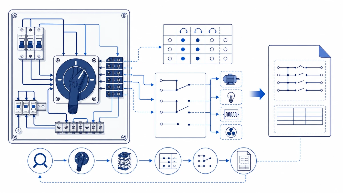
الشكل 4. يجب أن يتضمن الاستفسار الكامل التصنيف وتسلسل التلامس والتركيب والحاوية ومتطلبات المستند.
إذا اجتازت جميع الفحوصات الأربعة ولكن الدائرة لا تزال معطلة، فمن المحتمل أن يكون العطل خارج مفتاح الكامة نفسه. قم بمراجعة مخطط الأسلاك وبرنامج الاتصال مقابل توصيلات الدائرة الفعلية قبل تصعيد طلب الاستبدال.
الأسئلة الشائعة
ما هو الحد الأدنى من المعلومات اللازمة للحصول على مخطط أسلاك مفتاح كاميرا دوّار؟
أنت بحاجة إلى رمز الطراز الكامل من لوحة الاسم، وعدد مواضع التبديل، والجهد المقنن والتيار. إن توفير نوع التطبيق - مثل عكس المحرك، أو بدء التشغيل بنجمة-دلتا، أو التبديل العام للمحدد - يسمح للمورد بمضاهاة برنامج التلامس مع الواجب المذكور قبل إصدار المخطط، مما يقلل من فرصة استلام مستند غير صحيح.
كيف يمكنني تحديد برنامج التلامس لمفتاح كاميرا مع لوحة اسم غير مقروءة؟
قم بحساب عدد طبقات قرص الكامة لتحديد عدد الأعمدة، ثم قم بتدوير عمود المشغل يدويًا خلال كل موضع أثناء فحص الاستمرارية عبر كل زوج من أزواج التلامس باستخدام مقياس أومتر منخفض المقاومة. قم بتسجيل النتائج كشبكة توضح الأزواج المغلقة في كل موضع. إن تقديم جدول التلامس المعاد بناؤه هذا إلى المورد يمنحهم معلومات كافية لمطابقة برنامج موجود أو تأكيد ما إذا كان هناك حاجة إلى بناء مخصص.
ما الذي تعنيه فئة الاستخدام AC-23A وما أهميتها عند تحديد مفتاح الكامة؟
AC-23A يعين المفتاح AC-23A مفتاحًا مصنفًا لعمل وكسر تيار التشغيل الكامل لمحركات الحث ذات القفص السنجابي، والذي يمكن أن يصل إلى ستة إلى ثمانية أضعاف تيار التشغيل المقدر أثناء التشغيل العابر. إن تحديد AC-23A بدلاً من AC-21A يضمن مطابقة مادة التلامس وهندسة فجوة التلامس وأحكام تبريد القوس الكهربائي مع مهمة التحويل الفعلية. يؤدي استخدام مفتاح ذو تصنيف أخف في دائرة تبديل المحرك إلى تسريع تآكل التلامس ويزيد من خطر اللحام في ظروف العطل.
هل يمكن إصلاح مفتاح الكامة الدوارة في الميدان، أم أنه يتطلب الاستبدال دائماً؟
يمكن في بعض الأحيان تنظيف التلامسات المؤكسدة أو الملوثة بالكربون وإعادتها إلى الخدمة إذا أكدت قياسات المقاومة أنها تقع مرة أخرى ضمن العتبة المحددة من الشركة المصنعة بعد المعالجة. إن قرص الكامة المتصدع أو مانع تسرب العمود الفاشل الذي يسمح بدخول الرطوبة أو تلف التتبع عبر جسم عازل حامل التلامس هي حالات تتطلب استبدال الوحدة بالكامل. إن محاولة الاستمرار في تشغيل مفتاح مع قرص كامات متصدع قد يؤدي إلى حدوث أعطال في سد الأعطال من موضع إلى آخر في الدائرة المتحكم فيها.
ما هو تصنيف IP الذي يجب تحديده لمفتاح الكاميرا في لوحة التحكم في المحرك الخارجي؟
IP65 هو الحد الأدنى القياسي IP65 للبيئات الخارجية أو بيئات الغسيل بموجب المواصفة القياسية IEC 60529، مما يوفر استبعادًا كاملاً للغبار وحماية كاملة ضد نفاثات المياه من أي اتجاه. يجب أن تحدد التركيبات المعرضة للانغماس المؤقت IP67 والنظر فيما إذا كانت الضميمة المخصصة المقاومة للعوامل الجوية مناسبة للموقع. تأكد من أن تصنيف IP ينطبق على الوحدة المجمَّعة بالكامل، بما في ذلك مانع تسرب المشغل والغطاء الطرفي، وليس فقط على مبيت حامل التلامس.
ما هي المدة التي يستغرقها الحصول على رمز نموذج مؤكد وعرض أسعار من Shieldhz؟
يمكن عادةً تأكيد التكوينات القياسية ذات المدخلات الفنية الكاملة بشكل أسرع من الطلبات غير المكتملة أو غير القياسية. تتطلب طلبات برامج الاتصال المعقدة التحقق من قابلية البناء قبل إصدار عرض الأسعار. إن تقديم صورة فوتوغرافية للوحة الاسم، ومخطط الأسلاك الموجود، وجدول تلامس مكتمل مع الاستفسار الأول يقلل بشكل كبير من دورة المراجعة لكل من التكوينات القياسية والمخصصة.
ما الفرق الرئيسي بين سلسلة مفاتيح الكامات الدوارة LW28 و LW42؟
سلسلة LW28 مصممة لقواطع اللوحة المدمجة ومهام مفاتيح الاختيار العامة متعددة المواضع عبر مجموعة من تكوينات القطب والموضع. تستوعب السلسلة LW42 تطبيقات التحكم في المحركات الصناعية ذات التيار العالي داخل إطار حامل تلامس أكبر مع أبعاد قواطع لوحة مختلفة وأنماط ثقوب تركيب مختلفة. يتطلب التبديل بين السلاسل التحقق من رسم فتحة اللوحة قبل الطلب، حيث إن الإطارين غير قابلين للتبديل من حيث الأبعاد. استخدم صفحات السلسلة المشار إليها أعلاه لمقارنة معلمات الإطار قبل إرسال استفسار.
شي، موكسي
يكتب شي، موكسي مقالات شيلدهز الفنية لمشتري التحكم الصناعي والمكونات الكهربائية، والتي تغطي مفاتيح الكامات الدوارة، ومفاتيح العازل، ومفاتيح فصل التيار المستمر الكهروضوئية، وأزرار الضغط، وأضواء المؤشر، والحاويات المقاومة للماء، والكتل الطرفية. تستند المقالات على خبرة شركة Zhejiang Shihe Electric Co., Ltd. في التصنيع والتصدير، مع التركيز العملي على اختيار الطراز وأوراق البيانات والرسومات والشهادات وتصنيفات IP وتفاصيل الاستفسار التي يجب على المشترين التأكد منها قبل الطلب.