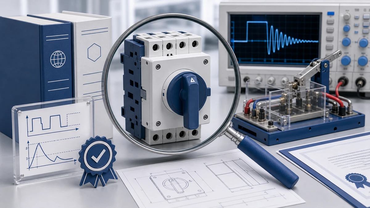
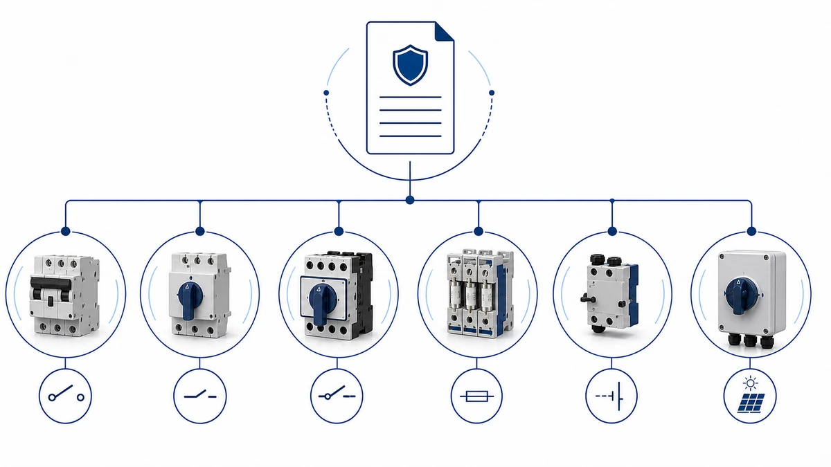
IEC 60947-3:2020+AMD1:2025 applies to switches, disconnectors, switch-disconnectors, and fuse-combination units for distribution and motor circuits, with rated voltage up to 1000 V AC or 1500 V DC. A DC switch disconnector must satisfy three core requirements under this standard: a verified isolation gap that withstands dielectric test voltage across open contacts, defined making and breaking capacity at rated direct current for the applicable utilization category, and stable on-state contact performance confirmed through type tests. For engineers specifying equipment in photovoltaic arrays, battery storage systems, or industrial DC drives, these requirements translate into a structured selection and verification process that differs significantly from AC isolator practice. This article explains each requirement, the DC-specific engineering rationale behind it, and how to confirm compliance before installation.
Why DC Switch Disconnectors Are Not Interchangeable with AC Isolators
The fundamental difference between a DC switch disconnector and a conventional AC isolator is the behavior of the arc at contact separation. In an AC circuit operating at 50 Hz or 60 Hz, current crosses zero 100 or 120 times per second. Each zero crossing is a natural extinction opportunity: the arc plasma cools between half-cycles, dielectric strength recovers across the gap, and the arc extinguishes without active quenching hardware.
In a DC circuit, current maintains continuous unidirectional flow with no natural zero crossing. Once an arc ignites at contact separation, it sustains itself as long as arc voltage remains below source voltage. In high-voltage PV strings operating at 1000 V DC or 1500 V DC, this means the arc can persist, depositing significant thermal energy on contact surfaces and generating carbonization debris that attacks surrounding insulation.
This behavior is why IEC 60947-3 defines separate DC utilization categories with dedicated making and breaking capacity test sequences, rather than simply extrapolating AC type-test results. An AC isolator applied to a DC circuit at equivalent voltage will sustain arcing that the device is not rated to interrupt. The consequences range from contact welding and premature erosion to sustained arc faults that damage adjacent wiring and enclosures.
For a thorough grounding in the principles underlying this standard, the IEC 60947-3 standard overview provides a useful orientation before working through the clause-level requirements described below.
Isolation Gap and Dielectric Performance Requirements
IEC 60947-3 requires a switch disconnector to fulfill both the switching function and the disconnector function simultaneously. The disconnector function demands a measurable air gap between open contacts that satisfies a defined dielectric test, confirming that no leakage current bridges the open-contact state during maintenance or emergency isolation.
For DC circuits, the isolation gap must withstand a dielectric test voltage applied between open poles and between poles and earth. The rated insulation voltage U(i) declared by the manufacturer must equal or exceed the maximum system voltage under all operating conditions, including cold-temperature open-circuit voltage peaks in PV installations. In modern string and combiner-box applications, U(i) values of 1000 V DC and 1500 V DC are the two dominant ratings.
Rated impulse withstand voltage U(imp) is a second dielectric parameter. It specifies the peak voltage level the insulation system must survive under transient overvoltage conditions without flashover. The applicable level depends on the rated voltage class of the device and is verified during type testing by applying impulse test pulses across open contacts and between all live parts and earth.
Power-frequency dielectric strength is verified separately by applying an AC withstand voltage across closed and open contact configurations for a defined duration. Buyers reviewing a type-test report should confirm that both impulse and power-frequency tests were conducted on the specific pole count and voltage rating being ordered, not on a different configuration within the same product family.
DC Utilization Categories: What Each Category Requires
IEC 60947-3 defines DC utilization categories to specify the electrical conditions under which a switch disconnector must reliably make and break current. Each category describes a particular load type through two parameters: the ratio of breaking current to rated current (I/I(e)), and the circuit time constant (L/R) in milliseconds. These two parameters together determine arc energy at contact separation.
Категория
Типовое применение
Current Ratio I/I(e)
Time Constant L/R
DC-20A
No-load to full-load resistive switching
1.0
Approximately 1 ms or less
DC-21A
Resistive and slightly inductive loads
1.0
Approximately 1 ms or less
DC-22A
Mixed resistive-inductive loads, motor braking
Up to approximately 4 x I(e)
Approximately 4 ms
DC-23A
Highly inductive DC loads, motor fields, electromagnets
Up to approximately 10 x I(e)
Approximately 15 ms
The suffix “A” denotes infrequent operator-actuated switching; the suffix “B” denotes frequent switching. This distinction affects contact endurance requirements and arc quenching geometry selection.
Why the L/R Time Constant Governs Category Selection
At a time constant of 15 ms, as specified for DC-23A, stored inductive energy sustains an arc for a substantially longer period than at 1 ms. Switch disconnectors rated for DC-23A must incorporate arc chutes, extended contact gap geometries, or magnetic blowout devices to force extinction within the rated breaking capacity. Applying a DC-21A rated device to a DC-23A load circuit results in arc duration and contact erosion that exceeds the device’s rated capacity.
In photovoltaic string circuits, the relevant category is typically DC-21A for predominantly resistive strings, or DC-22A where capacitive inverter input stages generate elevated transient currents at contact opening. The correct category should be confirmed by measuring the actual L/R time constant of the circuit rather than relying solely on load nameplate data. Motor field windings in particular can present time constants significantly above datasheet estimates.
For battery storage DC buses, the manufacturer’s breaking-capacity test report should be requested specifically at the relevant L/R value. A label marking of “1000 V DC” does not confirm breaking performance at 15 ms time constants.
Key Electrical and Mechanical Performance Requirements
Electrical Performance Parameters
Rated insulation voltage U(i): Must equal or exceed the maximum system voltage. For PV applications this is typically the maximum open-circuit voltage of the series string, which can reach 1500 V DC in utility-scale arrays.
Rated impulse withstand voltage U(imp): Verified by impulse test during type testing. The applicable level is defined by the rated voltage class declared by the manufacturer and should be confirmed in the test report.
Making and breaking capacity: The device must make and break at rated current under the L/R conditions corresponding to the specified utilization category. Making capacity governs behavior when the switch closes onto an energized circuit; breaking capacity governs contact performance at opening.
Leakage current across open contacts: Must satisfy the isolation criterion defined by the standard, confirming that no hazardous current flows through the open-contact gap during isolation. This is verified by the dielectric withstand test across open poles.
Contact resistance: Contact resistance across closed poles must remain stable over the mechanical endurance life of the device. The specific acceptable value is declared in the manufacturer’s datasheet and confirmed through millivolt-drop testing per the applicable clause. Buyers should request the as-tested contact resistance data from the type-test report rather than relying on a single nominal figure, as the critical parameter is stability over endurance cycles rather than initial value alone.
Mechanical Performance Parameters
Positive-break action: The actuator must deliver positive-break operation, ensuring contact separation regardless of operator actuation speed. In DC circuits this is critical: a slow or hesitant opening motion extends arc duration and increases contact erosion. IEC 60947-3 requires that positive-break action be maintained throughout the declared mechanical endurance life.
Mechanical endurance: The minimum number of no-load operating cycles is defined by the device category and is declared in the manufacturer’s datasheet. For applications involving frequent isolation and re-energization, endurance class should be confirmed against the projected switching frequency over the installation service life.
Enclosure ingress protection: For outdoor PV arrays, a minimum of IP65 per IEC 60529 is the standard baseline for weatherproof mounting. Sites subject to pressure washing, coastal salt spray, or potential water pooling require IP66 or IP67 to preserve insulation integrity over the system lifetime. A detailed comparison of these protection levels is available in the IP65 IP66 IP67 protection class guide.
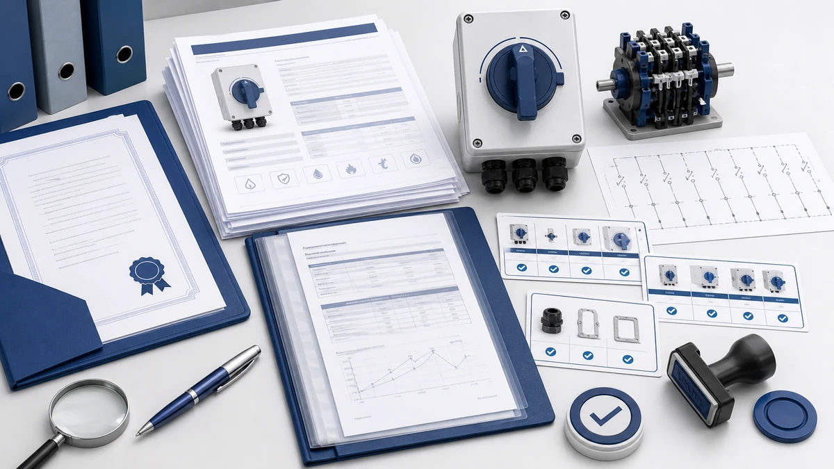
Рисунок 2. При выборе следует проверить постоянное напряжение, ток в сети, количество полюсов, корпус, кабельный ввод и документацию.
Arc Suppression Strategies in DC Switch Disconnector Design
Three principal engineering strategies are used to achieve reliable arc extinction in DC switch disconnectors.
Increased contact gap geometry: DC switch disconnectors require a minimum contact separation distance per pole that is significantly greater than AC equivalents at the same rated voltage. The specific gap dimension is design-dependent and should be confirmed in the product drawing, but the principle is consistent: the contact gap must ensure that arc voltage rises above source voltage to force extinction. This dimension is not universal across product families and should not be assumed from voltage rating alone.
Arc chute compartments with splitter plates: Metal splitter plates inserted in the arc path divide the arc column into series segments. Each segment adds a voltage drop across the arc column, progressively raising total arc voltage above the system voltage and forcing rapid extinction. The number and geometry of splitter plates is a manufacturer design variable; the performance outcome is verified through the breaking capacity test sequence.
Multi-break contacts per pole: Placing two or more contact breaks in series per pole multiplies the arc voltage per pole. This technique is widely used in DC switch disconnectors rated above 600 V DC and is a primary reason why pole count selection is a functional requirement, not merely a wiring convenience.
For a broader explanation of how these principles apply to DC isolation duty, the DC switch disconnector technical guide provides additional context on design classification and application mapping.
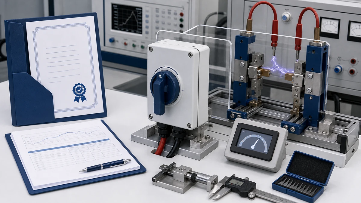
Рисунок 3. Перед подачей напряжения необходимо сверить контекст подключения с контактной схемой производителя.
Type Testing and Verification Procedures
Type testing under IEC 60947-3 establishes that a device design meets rated performance before production units enter service. Type tests are conducted on representative samples and are not repeated on every production unit. The tests cover dielectric performance, making and breaking capacity, temperature rise, and mechanical endurance.
Dielectric and Insulation Verification Sequence
Insulation qualification precedes switching tests. Impulse withstand voltage is applied across open contacts and between poles and earth at the U(imp) level declared by the manufacturer. Power-frequency dielectric withstand is then applied across all contact pairs and to exposed conductive parts for a defined duration. Failure at either stage requires the device to be redesigned before the test program continues.
DC Making and Breaking Capacity Test Sequence
Pre-test baseline: ambient temperature is confirmed within the standard test range and contact resistance is measured using a micro-ohmmeter to establish baseline.
Circuit configuration: the test circuit is set to the applicable DC utilization category, with rated operational voltage U(e) and the specified L/R time constant.
Making operations: rated making current is applied at rated voltage for the required number of operations defined by the test sequence.
Breaking operations: rated breaking current is interrupted at rated voltage; arc duration and contact erosion are recorded for each operation.
Post-test inspection: contact resistance is re-measured and compared against the pre-test baseline; the contacts, arc chutes, and insulation are inspected for welding, excessive erosion, or carbonization damage.
The type-test report should document actual recorded arc durations and contact erosion measurements from the breaking capacity sequence. These figures reveal how much margin exists above the rated minimum and are more informative than the certificate alone.
Temperature-Rise Testing
Temperature-rise testing passes rated operational current through closed contacts until thermal equilibrium is reached. The standard limits the temperature rise of terminals to 50 K above ambient under standard test conditions. For DC isolator applications in photovoltaic systems where continuous current flows during daylight hours, this test reflects the most thermally demanding normal operating condition. If the installation ambient temperature exceeds the 40 degrees Celsius test baseline, supplementary derating data should be requested from the manufacturer.
Buyers should verify that the temperature-rise test was conducted at the terminal torque and conductor cross-section specified for the installation. Under-torqued connections and mismatched conductor sizes increase contact resistance and can cause terminal temperatures to exceed the test values even at rated current.
Контрольный список по документации по закупкам
When purchasing an IEC 60947-3 compliant DC switch disconnector, request the following as a minimum documentation package:
Type-test report from a recognized laboratory covering dielectric withstand, DC making and breaking capacity, temperature rise, and mechanical endurance
Certificate of conformity referencing the specific model, pole count, voltage rating, and utilization category ordered
Product datasheet with rated parameters including U(i), U(imp), I(e), utilization category, mechanical endurance class, and IP rating
Wiring diagram and panel cutout drawing for the specific model variant
Confirmation that the test report pole count and voltage rating match the units being shipped
A generic family approval certificate covering a range of models does not constitute verification for a specific configuration. The test report must correspond to the exact model, pole count, and voltage rating being installed.
How to Select the Right IEC 60947-3 Compliant DC Switch Disconnector
Step 1: Confirm System Voltage Against Rated Insulation Voltage
Begin with the maximum DC bus voltage under open-circuit conditions, including the cold-temperature V(oc) peak for PV installations. The rated insulation voltage U(i) must equal or exceed this value. Using a 1000 V DC rated device in a 1500 V DC system violates IEC 60947-3 and creates a dielectric failure risk regardless of current rating.
Step 2: Determine Rated Current and Apply Temperature Derating
Identify the maximum continuous load current, then apply a derating factor for ambient temperatures above 40 degrees Celsius. The applicable derating curve is manufacturer-specific and should be obtained from the product datasheet rather than assumed from a generic industry rule. Select the utilization category that matches the actual L/R time constant of the circuit.
Step 3: Select Pole Count for Arc Extinction
DC circuits require series-connected poles to achieve sufficient arc extinction voltage per pole. A 1000 V DC circuit typically requires at least a 2-pole series configuration; 4-pole configurations provide additional margin and are common in combiner-box and inverter-level isolation. The GF51 Разъединительный выключатель постоянного тока PV is designed with this pole-series requirement integrated into its contact architecture, making it suitable for string-level and sub-array isolation in solar installations.
Step 4: Specify Mounting Format and Enclosure IP Rating
Confirm DIN rail or panel-mount compatibility and verify enclosure IP class against the installation environment. For rooftop and ground-mount PV arrays, IP65 is the baseline; sites with pressure washing, coastal exposure, or water pooling risk require IP66 or IP67. Pole count, current rating, and IP class together define the installation-ready specification.
Quick Selection Reference
Maximum DC voltage confirmed to be at or below U(i)
Continuous current with temperature derating applied
Utilization category confirmed from actual circuit L/R measurement
Pole count sufficient for arc extinction at rated voltage
Mounting format and cutout dimensions verified against panel drawing
Enclosure IP rating matched to installation environment class
Full documentation package including test report confirmed before order
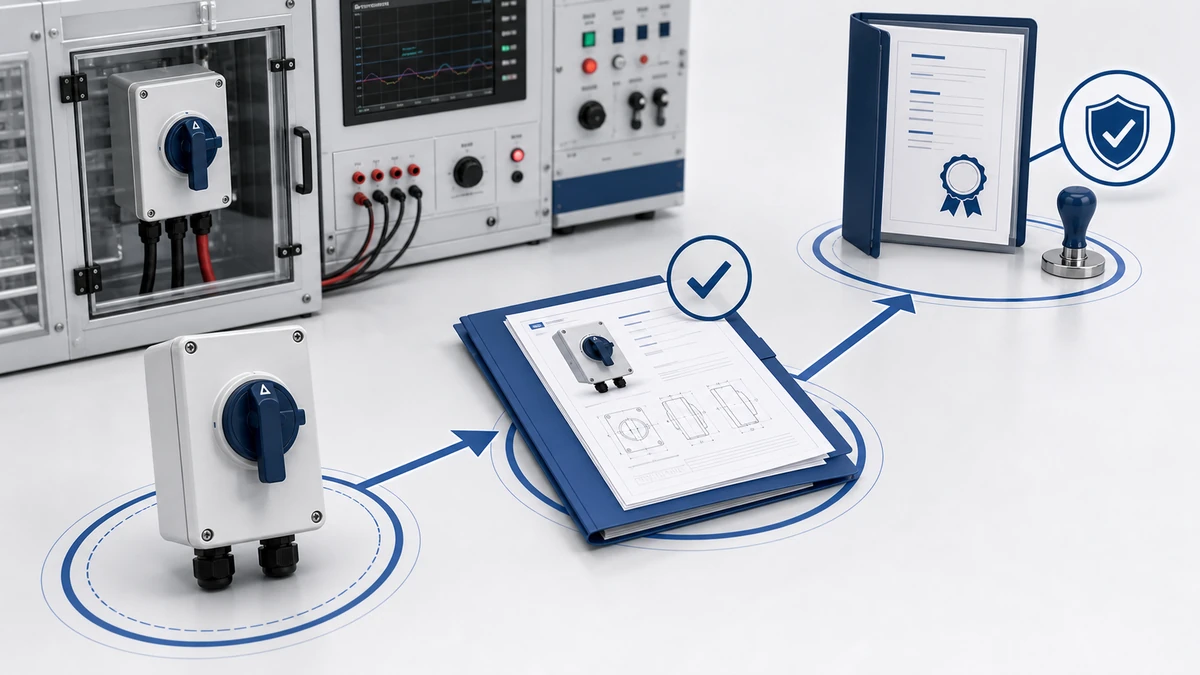
Рисунок 4. Полный запрос должен включать номинал, последовательность контактов, монтаж, корпус и требования к документам.
How Shieldhz Confirms IEC 60947-3 Compliance for DC Switch Disconnector Orders
Shieldhz is the export brand of Zhejiang Shihe Electric Co., Ltd., founded in 2014 and based in Yueqing, Zhejiang. The facility covers more than 5000 square meters, employs over 100 people, and operates more than 40 machines under documented production procedures. The quality management system is certified to ISO 9001, and products across the range carry CE, TUV, CB, UKCA, UL, CCC, and RoHS documentation where applicable to the specific model and market.
For DC switch disconnectors, Shieldhz applies a three-stage process to confirm IEC 60947-3 compliance before shipment.
Stage 1: Application intake and technical clarification. When a buyer submits an inquiry, the engineering team collects the parameters that govern compliance for the specific circuit: operating voltage up to 1500 V DC for PV applications, maximum continuous current per pole, utilization category, pole count, required IP rating, mounting format, and applicable national or regional installation standard. For solar disconnect applications, buyers are asked to confirm the string open-circuit voltage, the array-side or inverter-side installation position, and whether the system operates at 1000 V DC or 1500 V DC string architecture. This intake determines which model within the DC isolator range is appropriate for the application.
Stage 2: Design confirmation against IEC 60947-3 parameters. Once the model is identified, Shieldhz confirms the rated insulation voltage U(i), rated impulse withstand voltage U(imp), utilization category, and conditional short-circuit current rating against the buyer’s circuit data. The contact program and wiring diagram for the specific pole count and current rating are verified against the production drawing. For applications where the buyer provides a panel layout or system schematic, the engineering team checks dimensional compatibility and confirms that the enclosure IP class, terminal torque specification, and conductor cross-section range are documented in the datasheet.
Stage 3: Documentation and certification delivery. Before shipment, Shieldhz prepares a documentation package that includes the type-test report, product datasheet with rated parameters, wiring diagram, panel cutout drawing, and certificate of conformity. The certificate references the specific model, pole count, voltage rating, and utilization category. Buyers with project-level IEC 60947-3 compliance requirements can request TUV or CB scheme documentation where available for the specific model ordered. Procurement teams that supply circuit diagrams or load nameplates with their inquiry receive a written technical confirmation of model suitability before the order is placed.
The full IEC 60947-3 standard document is available directly from the IEC webstore publication page for engineering teams that need to work from the source text.
Часто задаваемые вопросы
What is the difference between a DC switch disconnector and a standard AC isolator?
A DC switch disconnector incorporates contact gap geometries, arc chute compartments, and multi-break configurations specifically engineered to extinguish arcs in the absence of a natural current zero crossing. A standard AC isolator relies on the 50 Hz or 60 Hz zero crossing for arc extinction and will sustain hazardous arcing if used to interrupt DC loads at rated DC voltages. IEC 60947-3 addresses this distinction by defining separate DC utilization categories with dedicated test sequences.
Which IEC 60947-3 utilization category applies to a photovoltaic string disconnect?
Most PV string disconnect applications fall under DC-21A for predominantly resistive string circuits. Where capacitive inverter input stages generate elevated transient currents at contact opening, DC-22A is the more conservative and appropriate designation. The correct category should be confirmed by measuring the actual circuit time constant rather than assumed from the inverter nameplate alone.
How many poles does a 1000 V DC switch disconnector typically require?
A 1000 V DC circuit typically requires at least a 2-pole series configuration to distribute arc extinction voltage across multiple contact gaps. Four-pole configurations are common in combiner-box and inverter-level isolation applications where additional voltage margin and redundancy in the arc extinction path are engineering priorities.
What does the L/R time constant mean in a DC switching specification?
The L/R time constant is the ratio of circuit inductance to resistance, expressed in milliseconds. It determines how long stored inductive energy sustains the arc after contacts open. A higher time constant requires more robust arc quenching hardware and is the primary parameter distinguishing one DC utilization category from another. DC-23A specifies approximately 15 ms, DC-22A approximately 4 ms, and DC-21A approximately 1 ms.
Can a DC switch disconnector rated at 1000 V DC be used in a 1500 V DC PV system?
No. The rated insulation voltage U(i) and rated operational voltage U(e) must equal or exceed the maximum open-circuit voltage of the array under all conditions, including cold-temperature V(oc) peaks. Installing a 1000 V DC rated device in a 1500 V DC system violates IEC 60947-3 and creates a dielectric breakdown risk across open contacts and between poles and earth.
What IP rating is required for a DC switch disconnector installed outdoors on a rooftop PV array?
A minimum of IP65 per IEC 60529 is the standard baseline for outdoor weatherproof mounting, providing protection against dust ingress and water jets from any direction. Sites subject to periodic pressure washing, coastal salt spray, or potential water pooling should specify IP66 or IP67. The specific IP requirement for a given installation should be confirmed against the environmental classification of the site and the requirements of the applicable installation standard.
What documentation should I request when purchasing an IEC 60947-3 compliant DC switch disconnector?
At minimum, request the type-test report from a recognized laboratory covering dielectric withstand, DC making and breaking capacity at the specified utilization category, temperature-rise results, and mechanical endurance cycles. The report should correspond to the specific model, pole count, and voltage rating being ordered. In addition, request the certificate of conformity, product datasheet with full rated parameters, wiring diagram, and panel cutout drawing. A generic family approval that covers multiple configurations is not a substitute for documentation specific to the ordered variant.
Ши, Мукси
Ши, Мукси пишет технические статьи Shieldhz для покупателей промышленных систем управления и электрических компонентов, охватывая поворотные кулачковые переключатели, разъединители, PV DC разъединители, кнопки, индикаторные лампы, водонепроницаемые корпуса и клеммные блоки. Статьи основаны на опыте производства и экспорта компании Zhejiang Shihe Electric Co., Ltd., с практическим акцентом на выборе модели, технических характеристиках, чертежах, сертификации, рейтингах IP и деталях запроса, которые покупатели должны подтвердить перед заказом.