Rotary Cam Switch Panel Mounting: Shaft Length, Door Clearance, and Handle Selection
Use a practical buyer checklist to evaluate rotary cam switch panel mounting inputs, documentation, approval controls and the exact rotary cam switch route.
Rotary cam switch panel mounting should be verified as a mechanical interface before the order is locked: shaft length, panel stack, door clearance, handle projection and documentation must match the selected contact program and the buyer’s enclosure.
Send the supplier the measured panel or door stack, desired handle position, panel cutout expectations and any clearance constraints.
Confirm the electrical route and the mechanical route together; a valid contact program can still fail the enclosure if shaft length or handle clearance is wrong.
Request the exact-model drawing, datasheet and relevant certificate package before purchasing for a production build.
Start with the mounting interface, not only the switching diagram
Panel mounting is a separate buyer decision because the same switching intent can require different shafts, handles, bezels, front plates or mounting depths. The decision is not only “which function,” but whether the complete operator-to-contact route fits the panel, door and enclosure layout.
What this decision owns
This article focuses on the physical mounting interface: panel thickness, front hardware, shaft length, door clearance, handle style and drawing verification. It does not repeat door-interlock product selection, and it does not treat the operator as proof of a complete machine safety function.
For sourcing teams, this means the purchase line should not stop at a function description. It should identify the mounting style, handle requirement and document package needed to verify the interface before production.
Where this fits in the product search
Используйте диапазон поворотных кулачковых переключателей to identify available product families, then narrow the route by function, electrical duty and mounting detail. The final check should be against the current drawing and datasheet for the exact model being quoted.
Build a measured panel-mounting stack
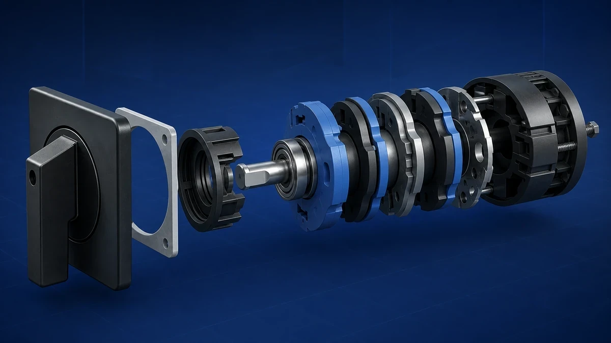
The panel-mounting stack should be measured before selecting the shaft and handle because every layer between the operator and switch body changes the required reach. Include the enclosure wall or door, gasket, nameplate, legend plate, escutcheon, washer, nut and any spacer used in the build.
An exact drawing identifies the interfaces that must be controlled for the approved model route.
Measurements to capture
Prepare a simple dimension set before quotation:
Panel or door thickness at the mounting location.
Any front plate, legend plate or escutcheon thickness.
Gasket or seal thickness if it affects compression or handle seating.
Distance from the front surface to the internal mounting plane.
Internal clearance behind the panel for the switch body and wiring route.
Door swing clearance relative to nearby equipment, flanges or handles.
Required handle orientation in each position.
Use drawings for holes, anti-rotation and front hardware
Panel cutouts should be confirmed from the supplier’s drawing, not inferred from a similar unit. Hole diameter, anti-rotation features, front plate geometry and fastener arrangement can vary by model and handle route.
The broader rotary cam switch selection guide can support early screening, but the panel interface should be closed with the exact drawing for the quoted model.
Measurement or feature
Почему это важно
Best confirmation source
Толщина панели
Determines whether the selected mounting hardware and shaft route can seat correctly
Exact-model drawing
Передняя панель или панель легенды
Changes the operator stack and visible front interface
Drawing and buyer layout
Anti-rotation feature
Helps prevent misalignment where required by the design
Drawing
Switch body depth
Affects clearance behind the door or panel
Drawing and datasheet
Handle projection
Affects operator access and adjacent-door clearance
Drawing
Door closed gap
Confirms whether the switch body and wiring route fit without contact
Buyer enclosure measurement
Set shaft length from the closed-door geometry
Shaft length should be selected from the actual closed-door geometry, not from the nominal enclosure depth alone. A shaft that looks suitable in an open-door layout can be too short after plates and gaskets are added, or too long when internal clearance is tight.
Short shaft, long shaft or extension route
The shaft route depends on where the cam switch body is mounted relative to the front operator. In some builds the switch mounts directly behind the panel; in others the handle is on a door and the switch body is mounted deeper inside the enclosure.
Route decision
When it is typically considered
Buyer verification needed
Direct panel mounting
Switch body sits close behind the operator
Panel thickness, front hardware and body depth
Longer shaft route
Operator is separated from the switch body by door depth or internal layout
Door closed dimension and alignment path
Shaft extension or coupling route
Door-mounted handle must reach a body mounted further inside
Enclosure drawing and allowed misalignment from the exact documentation
Alternative layout
Shaft route creates interference or excessive projection
New mounting plane, handle position or switch location
Clearance checks that prevent late rework
Check both the static and moving conditions. The switch may fit when the door is open but interfere with ducting, the enclosure lip or adjacent equipment when the door closes.
Practical clearance checklist:
Verify the door can close without the switch body, shaft or handle hardware contacting internal parts.
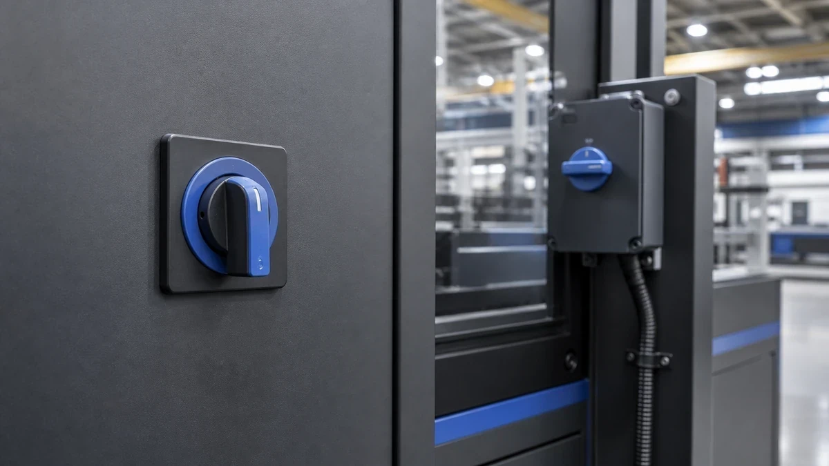
Confirm handle projection does not block adjacent handles, meters or access paths.
Check that the handle can rotate through the required positions without hitting a raised frame or cover.
Confirm the shaft axis remains aligned with the switch body in the installed condition.
Reserve access for installation, inspection and replacement according to the buyer’s maintenance practice.
Sample review should connect the exact item to its current drawing and requested evidence package.
Select the handle after the shaft route is known
The handle should be selected after the mounting route is known because handle projection, grip style, front plate and locking features can change the required front clearance. A handle that is comfortable for an operator may still be unsuitable if it conflicts with the enclosure layout or documentation requirements.
Handle style by operator task
Handle choice is a commercial and ergonomic decision as well as a mechanical one. Confirm the exact handle option offered for the selected model rather than assuming interchangeability across product families.
Handle requirement
Typical buyer reason
Verification point
Compact knob
Limited front-panel space
Projection and finger clearance
Pistol or lever handle
Easier manual operation on larger front panels
Rotation envelope and adjacent-device spacing
Padlockable handle
Buyer wants a lockable operating position where the exact model supports it
Locking positions and drawing details
Keyed or special operator request
Access control or application-specific operating procedure
Exact option availability and documentation
Marked front plate
Clear position indication
Legend, language, angle and position count
Padlocking and emergency-stop style requests
If a padlockable handle is requested, confirm which positions can be locked for the exact model and handle option. Do not assume that one lockable configuration applies to every current, pole count or contact program.
If an emergency-stop style operator or color scheme is requested, treat it as an operator selection input only. Selecting an operator does not validate a complete machine safety function; the final safety function depends on the full machine design, risk assessment, control architecture and applicable documentation.
Handle-selection action list:
Define the required handle position labels.
Confirm the number of handle positions and angular indexing.
Check whether the handle must be lockable, and in which position.
Confirm front projection and rotation envelope.
Request the drawing for the exact handle and front-plate combination.
Keep the contact program tied to the mechanical route
The contact program must be confirmed together with the panel route because poles, positions and stages can change the switch body depth and installation envelope. A mechanical mounting decision made before the contact program is finalized may need revision.
Function and contact stages affect body depth
The switching function determines how contacts open and close across handle positions. For a function-level refresher, use the rotary cam switch functions guide rather than repeating the broad definitions here.
Poles and contact stages can also affect the physical build. The positions, poles and contact stages guide is useful when translating a schematic requirement into a practical contact program, but the final body depth should still be checked on the exact model drawing.
Motor-control duties need electrical and mechanical confirmation
Motor-control applications can require specific attention to duty, utilization category, voltage, current and contact sequence. The rotary cam switch motor-control guide can support early route selection, while final suitability remains dependent on the exact documentation and buyer application.
Do not separate this electrical check from the panel layout. A larger or more complex contact program may change rear clearance, shaft alignment or available handle options.
Installation conditions change the product-route and document questions a buyer must resolve.
Match the front interface to the enclosure environment
The front interface should be matched to the actual enclosure environment because sealing, materials and handle hardware are exact-model and application dependent. Do not apply a generic IP class or environmental claim to an unconfirmed handle and mounting combination.
Panel location and exposure
The same switch function may be installed in a dry indoor cabinet, a machine-side operator station or an enclosure exposed to washdown, dust or outdoor conditions. Each environment changes what the buyer should request from the supplier.
Environment question
Why it affects mounting
What to request
Is the handle inside or outside a protected cabinet?
Front sealing and material exposure can differ
Exact handle and front-interface datasheet
Is the panel subject to dust, oil mist or moisture?
Front hardware and sealing expectations may change
Exact-model environmental information
Is the enclosure cleaned or sprayed?
Water exposure assumptions must be documented
Drawing and datasheet for the selected front assembly
Is outdoor exposure possible?
UV, corrosion and temperature considerations may apply
Destination-market and application review
Is there operator PPE or glove use?
Grip size and spacing can affect usability
Handle drawing and buyer ergonomic check
Sealing claims must come from the exact model documentation
If the buyer requires a stated ingress-protection level or environmental property, request it for the exact configuration. Handle type, panel thickness, gasket arrangement and installation method can affect what can be claimed.
Buyer verification checklist:
Confirm the enclosure location and exposure.
Identify any required environmental statement before quotation.
Ask whether the stated property applies to the selected handle and mounting hardware.
Keep the drawing, datasheet and certificate package with the purchase record.
Recheck the interface if the handle, shaft or front plate changes.
Request drawings, datasheets and certificates before purchasing
Documentation should be requested before purchasing because it is the evidence used to confirm mounting, electrical duty and destination-market requirements. A catalog description is not enough for production panel verification.
What the drawing should settle
The drawing should confirm the buyer-facing mechanical interface. At minimum, it should resolve the shaft route, panel cutout, mounting depth, front projection and handle rotation envelope for the quoted configuration.
Drawing review action list:
Match the model number on the drawing to the quotation.
Check panel cutout and anti-rotation details.
Confirm body depth behind the panel.
Confirm shaft length or extension details.
Confirm handle projection and position angle.
Check whether the drawing revision is current for the quoted product.
How standards references should be handled
Standards references should be checked against the exact product documentation and the intended market. For scope context, the IEC 60947-3 scope describes switches, disconnectors, switch-disconnectors and fuse-combination units within stated distribution- and motor-circuit AC/DC limits.
That scope statement does not by itself confirm that a specific model, handle, mounting route or buyer application is suitable. Request the relevant datasheet, certificate or declaration package for the exact model and destination market.
How Shieldhz confirms a rotary cam switch route
Shieldhz confirms a route by matching the switching requirement, electrical duty, contact program, mounting interface, handle route and documentation request before quotation. Final suitability is confirmed against current product documentation and the buyer’s application.
Documentation control, sample acceptance and protective packing are separate handover checks.
Pre-quotation input checklist
Provide these inputs to reduce revision loops:
Switching function required by the machine or panel design.
AC or DC duty.
Voltage, current and utilization category.
Pole count and contact program.
Number of positions and handle indexing.
Panel mounting route, panel thickness and shaft-length constraints.
Door clearance, enclosure depth and handle projection limits.
Environment and destination-market considerations.
Requested drawing, datasheet and certificate package.
Output the buyer can request
A practical quotation route can include the proposed model, handle option, mounting notes and document package available for review. If the buyer changes the contact program, enclosure layout, handle style or destination market, the route should be rechecked before release.
This process is intended to verify the interface and documentation path. It does not replace the buyer’s machine-level engineering review, installation responsibility or final application validation.
Conclusion
Rotary cam switch panel mounting is a mechanical and documentation decision as much as an electrical selection. Shaft length, panel stack, door clearance and handle style should be verified with the same discipline as voltage, current, utilization category and contact program.
For production purchasing, the safest commercial step is to send the measured mounting details before quotation and request the exact-model drawing, datasheet and certificate package. Final suitability depends on the current product documentation and the buyer’s application.
Часто задаваемые вопросы
What is the most common mistake in rotary cam switch panel mounting?
The common mistake is selecting the switching function first and leaving shaft length, panel thickness and handle clearance until the panel is already built. The contact program and the mounting route should be checked together before release.
How do I know the correct shaft length?
Use the closed-door geometry, not only the enclosure depth. Measure every layer between the handle and switch body, then confirm the required shaft or extension route against the exact drawing.
Can I use the same handle on every rotary cam switch model?
Do not assume that. Handle availability, projection, locking features and front plates are model-dependent and should be confirmed from the quotation and product documentation.
Does a padlockable handle confirm a complete safety function?
No. A padlockable handle is a selected operator feature for the exact configuration where offered. It does not validate a complete machine safety function or replace the buyer’s application-level safety review.
What documents should procurement request before placing an order?
Request the exact-model drawing, datasheet and any required certificate or declaration package for the destination market. The drawing should confirm panel cutout, shaft route, body depth, handle projection and position arrangement.
When should the mounting route be rechecked?
Recheck it whenever the contact program, pole count, handle type, enclosure, panel thickness, door layout, environmental requirement or destination market changes. Even a small change can affect the mounting interface or documentation route.
Ши, Мукси
Ши, Мукси пишет технические статьи Shieldhz для покупателей промышленных систем управления и электрических компонентов, охватывая поворотные кулачковые переключатели, разъединители, PV DC разъединители, кнопки, индикаторные лампы, водонепроницаемые корпуса и клеммные блоки. Статьи основаны на опыте производства и экспорта компании Zhejiang Shihe Electric Co., Ltd., с практическим акцентом на выборе модели, технических характеристиках, чертежах, сертификации, рейтингах IP и деталях запроса, которые покупатели должны подтвердить перед заказом.