مفاتيح الكامة الدوارة هي مفاتيح تبديل متعددة المواضع تُستخدم لتوجيه أو عزل أو تسلسل الدوائر الكهربائية في البيئات الصناعية. عبر مسارات شيلدهز الدوارة، يغطي مفتاح LW28 عائلة مفاتيح الكامات ذات الحدبة من 10 أمبير إلى 315 أمبير، ويغطي LW42 تطبيقات التحويل المدمجة 20 أمبير و25 أمبير و32 أمبير، ويغطي SH30 مهام العازل من 20 أمبير إلى 125 أمبير. وتخضع التصنيفات الدقيقة لورقة البيانات المحددة وفئة الاستخدام IEC 60947-3:2020+AMD1:2025، لذا تظهر هذه المفاتيح في لوحات التحكم ومحطات أدوات الماكينات وخزانات التوزيع حيثما يحتاج المشغلون إلى تبديل موثوق وقابل للتكرار للدائرة عبر مواضع محددة. إن حتميتها الميكانيكية - ملامح الكامة الثابتة، والمفاتيح المفهرسة، وتسلسل الكسر قبل الصنع - تجعلها الخيار المفضل على البدائل القابلة للبرمجة في البيئات الحرجة للسلامة أو البيئات عالية الاهتزاز. تغطي هذه المقالة كيفية عملها، وأين تتناسب، وكيفية اختيارها وتوصيلها بالأسلاك، وكيف تبدو الصيانة في سياقات النشر الثلاثة.
كيف يعمل مفتاح الكاميرا الدوارة
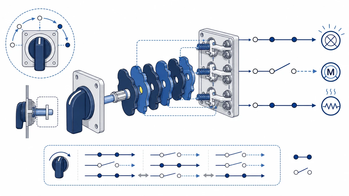
تفاعل قرص الكاميرا وجسر التلامس
يتم تحديد كل قرص كامة بفصوص مرتفعة ووديان غائرة. أثناء دوران عمود المشغل - عادةً في خطوات مفهرسة بزاوية 30 درجة أو 45 درجة أو 60 درجة - تقوم هندسة الفص إما برفع جسر التلامس المحمل بنابض بعيدًا عن طرفه الثابت (حالة الفتح) أو تسمح للجسر بالاستقرار بإحكام على كلا الطرفين (حالة الإغلاق). تتم معايرة التحميل المسبق لنابض التلامس أثناء التصنيع للحفاظ على قوة تلامس متسقة عبر التحمل الميكانيكي المقدر للمفتاح.
تعتبر مادة التلامس أمرًا بالغ الأهمية للتبديل الموثوق. إن أكسيد القصدير الفضي (AgSnO2) هو الخيار السائد لمفاتيح الكامة الصناعية، حيث يوفر مقاومة ثابتة لتآكل القوس الكهربائي تحت كل من الأحمال المقاومة والاستقرائية. تحدد المواصفة القياسية IEC 60947-3:2020+AMD1:2025 متطلبات قدرة التصنيع والكسر التي يجب أن تفي بها ملامسات مفاتيح الكامة، بما في ذلك الأداء تحت فئة الاستخدام AC-23A لأحمال المحركات. يصل جهد العزل المقنن (Ui) لمفاتيح الكامة الصناعية عادةً إلى 690 فولت تيار متردد مع جهد تحمل نبضي مقنن (Uimp) يبلغ 6 كيلو فولت أو أعلى، وكلاهما تم التحقق منه في ظل ظروف اختبار النوع IEC 60947-3.
تبديل التسلسل والفهرسة الموضعية
يتم تحديد تسلسل التبديل من خلال العلاقة الزاوية بين نمط شحمة كل قرص كامات ومواضع الفاصلة المفهرسة للعمود. في دائرة عكسية نموذجية للمحرك ذات 4 مواضع، يتم ترتيب كومة الكامة بحيث تنفتح جميع التلامسات لفترة وجيزة أثناء الانتقال - تسلسل كسر قبل الصنع يمنع حدوث دوائر قصيرة بين المواضع.
تسلسل الكسر قبل الصنع ليس تلقائيًا في جميع طرازات مفاتيح الكامة. تأكد من ترتيب قرص الكامة في مخطط التلامس الخاص بالشركة المصنعة قبل تحديد مفتاح الكامة قبل إجراء التبديل العكسي. عند استبدال مفتاح الكامة في منتصف المشروع، تحقق من تطابق زاوية الخطوة المفهرسة مع الزاوية الأصلية؛ عدم التطابق يغير تسلسل التبديل بالنسبة لعلامات مقبض المشغل.
يتم تجميع مكدس قرص الكامة في تسلسل محدد أثناء التصنيع، وبالتالي فإن منطق التحويل ثابت وقابل للتكرار - وهي ميزة موثوقية رئيسية مقارنة بالبدائل القابلة للبرمجة في مهام العزل الحرجة للسلامة. إن ل.و.28 و ل.و.42 تتبع السلسلة من Shieldhz هذه البنية ذات الأقراص المكدسة، مع ملفات تعريف الكامات المطابقة لمخططات الدوائر الكهربائية الدولية القياسية للتحكم في المحرك وخدمة التحويل.
الشكل 1. المفهوم الأساسي وراء اختيار تطبيقات مفاتيح الكامات الدوارة.
تطبيقات مفاتيح الكامات الدوارة في لوحات التحكم الصناعية
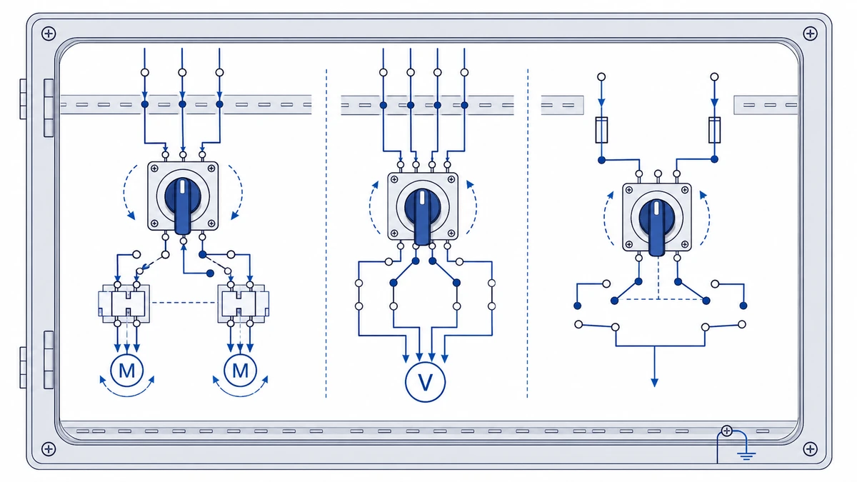
التحكم في المحرك وعكس اتجاهه
في لوحات التحكم في الأدوات الآلية، تتعامل مفاتيح الكامة مع تبديل المحرك للأمام/الخلف تحت فئة الاستخدام AC-23A، والتي تغطي صنع وكسر أحمال المحرك ذات المحتوى الاستقرائي العالي. يضع التركيب النموذجي المفتاح على جانب الحمل من الملامس الرئيسي، مع تشابك تسلسل موضع الكامة لمنع الربط المباشر بين الطور والمرحلة أثناء الانتقال.
بالنسبة للتبديل المباشر للمحرك، حدد مفتاح الكامة حسب التيار المقنن AC-23A، وتيار الحمل الكامل للمحرك، وبرنامج التلامس المحدد بدلاً من تعيين كيلوواط المحرك إلى اسم سلسلة فقط. تأكد دائمًا من التصنيف الحالي للتيار AC-23A في ورقة بيانات المنتج - فتصنيف AC-21A للمفتاح وتصنيف AC-23A الخاص به ليسا نفس الرقم، وتحديد التصنيف مقابل الفئة الخاطئة هو مصدر شائع للتآكل المبكر للتلامس.
محدد الفولتميتر ومحدد الأميتر الواجب
تستخدم خزانات التوزيع ثلاثية الأطوار عادةً مفاتيح الكامة كمفاتيح اختيار الطور للعدادات المثبتة على اللوحة. في هذا التطبيق، يتنقل المفتاح بين مواضع L1 وL2 وL3 وإيقاف التشغيل، موصلاً مدخلات العداد بكل مرحلة بالتسلسل. يجب أن تظل مقاومة التلامس مستقرة طوال فترة الخدمة لتجنب حدوث خطأ في القياس. تتبع ممارسة الأسلاك هنا تكوين نقطة نجمية، مع عودة جميع المواضع غير المستخدمة إلى حالة مفتوحة محددة بدلاً من أن تكون عائمة.
تغيير المصدر وعزله
بالنسبة للوحات الإمداد المزدوج - التيار الكهربائي بالإضافة إلى مولد أو مولدات الطاقة غير المنقطعة - يوفر مفتاح كاميرا متعدد الأقطاب من سلسلة LW42 تبديلًا متشابكًا ميكانيكيًا مع وضع إيقاف تشغيل محدد بين المصادر. وهذا يفي بمتطلبات الفصل في المواصفة القياسية IEC 60947-3:2020+AMD1:2025 لأجهزة العزل، مما يضمن عدم وجود مسار تغذية عكسية أثناء فترة الانتقال. تختلف مواصفات عزم الدوران الطرفي لهذه التركيبات حسب المقطع العرضي للموصل وحجم الطرفية؛ اتبع دائمًا ورقة بيانات الشركة المصنعة بدلاً من تطبيق رقم عام.
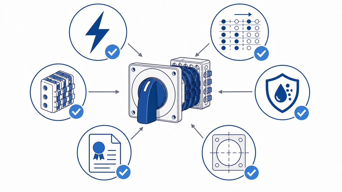
الشكل 2. يجب أن تربط فحوصات الاختيار الحمل وتسلسل التحويل والحاوية ومتطلبات التوثيق.
تطبيقات مفاتيح الكامات الدوارة في أدوات الماكينات
اتجاه عمود الدوران واختيار السرعة
في المخارط وماكينات التفريز ومراكز الماكينات، عادةً ما يدير مفتاح الكامة الدوارة تسلسل الأمام/الخلف/إيقاف التشغيل لمحرك عمود الدوران. هذا تطبيق دورة عمل متطلب: تحكم فئة الاستخدام IEC 60947-3:2020+AMD1:2025 فئة الاستخدام AC-23A في صنع أحمال المحرك وكسرها، مما يتطلب من المفتاح مقاطعة التيارات الحثية عند الجهد المقنن. يتم تصنيف مفتاح محدد عمود الدوران النموذجي في هذا الدور من 20 أمبير إلى 32 أمبير عند 380 فولت تيار متردد مع تصنيف التحمل الميكانيكي في ظروف عدم التحميل وفقًا لورقة بيانات الشركة المصنعة.
يتم تحديد سلسلة LW28 بشكل شائع لهذا التطبيق، حيث توفر ما يصل إلى 12 موضع تلامس مع ترتيبات أقراص كامات قابلة للتكوين تتطابق مع منطق التحويل لدوائر المحركات متعددة السرعات أو دوائر المحركات العكسية دون الحاجة إلى مراحل ترحيل إضافية.
مضخة سائل التبريد والتحكم في الدائرة المساعدة
عادةً ما تقوم أدوات الماكينات بتشغيل مضخات سائل التبريد، وأنظمة التشحيم، ودوائر إضاءة العمل كأحمال إضافية إلى جانب محرك عمود الدوران الرئيسي. يدمج مفتاح الكامة متعدد المواضع هذه الوظائف في محدد واحد مثبت على لوحة، مما يقلل من تعقيد الأسلاك. تعمل دارات مضخة سائل التبريد بشكل عام عند مستويات تيار منخفضة بشكل جيد ضمن تصنيف الحمل المقاوم لمعظم مفاتيح الكامة، ولكن يمكن أن يتجاوز تردد التبديل أثناء نوبة الإنتاج 500 عملية في اليوم، مما يجعل متانة التلامس عامل اختيار حقيقي.
بالنسبة للوحات ذات الوظائف المدمجة، توفر السلسلة LW42 تصميم كتلة تلامس معيارية تسمح للمهندسين بتكوين مسارات تبديل مستقلة لكل دائرة مساعدة داخل هيكل مدمج.
اعتبارات دورة العمل وتصنيف جهات الاتصال
تفرض بيئات أدوات الماكينة إجهادين مركبين: الحمل الحراري من التشغيل المستمر والصدمة الميكانيكية من اهتزاز عمود الدوران. تحافظ مواد التلامس المصنفة وفقًا للمواصفة IEC 60947-3 - عادةً AgSnO2 - على مقاومة تلامس مستقرة عبر عمر الدورة المقدرة، وهو أمر بالغ الأهمية عندما يغذي المفتاح بادئ تشغيل محرك أو دائرة إدخال محرك متغير التردد حيث يؤثر انخفاض الجهد بشكل مباشر على موثوقية التحكم.
يتم تحديد حماية دخول الضميمة بما لا يقل عن IP54 بشكل عام لقواطع لوحة أداة الماكينة للحماية من رذاذ سائل التبريد والتلوث بالقاذورات. في تطبيقات أدوات الماكينات ذات الدورة العالية، قم بتسجيل عدد العمليات منذ بدء التشغيل؛ يجب جدولة المفاتيح التي تقترب من عتبة الدورة المقدرة من الشركة المصنعة لفحص التلامس قبل الوصول إلى هذا الحد.
عند تحديد المواصفات لدائرة إدخال VFD، تأكد من أن الجهد الدفعي المقدر لمفتاح الكامة (Uimp) يغطي الارتفاعات العابرة الشائعة في خطوط خرج VFD. يعد تراكم النتوءات حول عمود المشغل سببًا رئيسيًا لتآكل الكامة؛ يعمل مانع التسرب الماسح أو الحذاء الواقي على إطالة عمر الخدمة بشكل كبير في تطبيقات الطحن.
تطبيقات مفاتيح الكامات الدوارة في خزائن التوزيع
مفاتيح الكامات مقابل أجهزة عزل الجهد المنخفض الأخرى
الجهاز
تبديل المراكز
التصنيف النموذجي
وظيفة العزل
مرجع IEC
مفتاح كاميرا دوارة
2 إلى 12 وظيفة
تأكيد تصنيف ورقة البيانات المحددة
نعم (الموضع المرئي)
IEC 60947-3
قاطع دارة كهربائية مصبوب
تشغيل/إيقاف التشغيل فقط
حتى 1600 أمبير
نعم (مع الإغلاق)
IEC 60947-2
عازل منصهر
تشغيل/إيقاف التشغيل فقط
حتى 630 أمبير
نعم
IEC 60947-3
المقاول
تشغيل/إيقاف (تشغيل/إيقاف (محرك الملف)
حتى 800 أمبير
لا (غير مصنفة للعزل)
IEC 60947-4-1
لا يتم تصنيف الملامس كجهاز عزل بموجب المواصفة IEC 60947-4-1 لأنه يفتقر إلى فجوة محددة خارج الحالة مرئية للمشغل. يوفر مفتاح الكامة الدوارة قفلًا ميكانيكيًا وتأكيدًا بصريًا لوضع الإيقاف - وهو شرط في العديد من إجراءات صيانة لوحة التوزيع.
عزل المغذي الوارد: يتم وضع مفتاح كامة مقنن بقوة 32 أمبير إلى 63 أمبير أمام عمود التوصيل للسماح بفصل الطاقة الآمن قبل صيانة اللوحة، مما يفي بمتطلبات العزل الخاصة بالفئة AC-22A من المواصفة IEC 60947-3:2020+AMD1:2025.
تحويل مقطع الناقل: يتيح مفتاح كاميرا ثلاثي المواضع (المصدر 1 / إيقاف التشغيل / المصدر 2) إمكانية التحويل اليدوي بين اثنين من مغذيات الإمداد دون موازاة بينهما، وهو ترتيب شائع في المنشآت المزودة بمولد احتياطي.
اختيار القياس والأجهزة: تعمل مفاتيح الكامات متعددة المواضع على توجيه محولات الجهد الكهربائي الثانوية إلى عدادات اللوحة، مما يسمح لمقياس واحد بقراءة مراحل أو دوائر متعددة بالتسلسل.
بالنسبة لتطبيقات التوزيع التي تتطلب تركيبًا مدمجًا، يجب مقارنة مسارات LW28 و LW42 حسب الإطار الحالي وفئة العمل والقطع وبرنامج التلامس بدلاً من تصنيف عام واحد. يمكن الوصول إلى نظرة عامة أوسع على عائلات المفاتيح المتاحة من خلال مجموعة منتجات مفاتيح Shieldhz ذات الكامات الدوارة.
الشكل 3. يجب التحقق من سياق الأسلاك التطبيقية بالمقارنة مع مخطط التلامس الخاص بالشركة المصنعة قبل التنشيط.
كيفية اختيار مفتاح الكاميرا الدوارة المناسب
معلمات الاختيار الرئيسية
المعلمة
النطاق النموذجي
إرشادات الاختيار
التصنيف الحالي
10 أمبير إلى 100 أمبير
مطابقة لتيار الحمل الكامل للدائرة؛ قم بتطبيق هامش اشتقاق 25% للأحمال الحثية تحت تيار متردد 23 أمبير
تصنيف الجهد (Ui)
240 فولت إلى 690 فولت تيار متردد
حدد جهد العزل المقنن عند أو أعلى من جهد النظام؛ 690 فولت تيار متردد يغطي معظم التطبيقات الصناعية ثلاثية المراحل
تستخدم اللوحة الداخلية المفتوحة عادةً IP40 إلى IP54؛ أما البيئات الخارجية أو بيئات الغسيل فتتطلب IP65 أو أعلى
قياسي
IEC 60947-3، IEC 60947-3، UL 508
تحكم IEC 60947-3:2020+AMD1:2025 المواصلات ومفصلات المفاتيح؛ وتنطبق المواصلات UL 508 على لوحات التحكم الصناعية في أمريكا الشمالية
تنطبق المواصفة القياسية IEC 60947-3:2020+AMD1:2025 على المفاتيح والمفصلات ومفصلات المفاتيح ووحدات دمج الصمامات لدوائر التوزيع ودوائر المحركات، بجهد مقنن يصل إلى 1000 فولت تيار متردد أو 1500 فولت تيار مستمر. تتوفر المواصفة القياسية الكاملة من متجر IEC الإلكتروني.
مطابقة فئة الاستخدام مع نوع الحمولة
تحدد المواصفة القياسية IEC 60947-3 فئات الاستخدام التي تؤثر بشكل مباشر على تصنيف المفتاح المناسب. تغطي الفئة AC-21A الأحمال المقاومة والحثية قليلاً، بينما تنطبق الفئة AC-23A على الأحمال الحركية. قد لا يكون المفتاح المصنّف 32A AC-21A مناسبًا إلا لتيار أقل تحت ظروف AC-23A، لذلك تأكد دائمًا من الفئة مقابل نوع الحمل الفعلي قبل تحديد المواصفات.
في خزانات التوزيع الخارجية أو العبوات الخارجية المعرضة للغبار والرطوبة، يصبح تصنيف IP مرشحًا أساسيًا قبل التصنيف الحالي. ويتحمل المفتاح الذي يفي بتصنيف IP65 الذي يفي بمعيار IEC 60529 IP65 نفاثات المياه منخفضة الضغط من أي اتجاه - وهو الحد الأدنى لمعظم البيئات الصناعية الخارجية. بالنسبة لظروف الغمر الكامل أو ظروف الغسل عالية الضغط، يلزم تصنيف IP67 أو IP69K.
يتبع عدد الأعمدة طوبولوجيا النظام: تستخدم الدوائر أحادية الطور 2P، وتستخدم الأنظمة ثلاثية الطور غير المؤرضة 3P، وتتطلب التركيبات التي يجب فيها تبديل المحايد أو عزله 4P. إن استخدام مفتاح ثلاثي الأقطاب على نظام يتطلب تبديل محايد يترك المحايد نشطًا أثناء العزل، وهو ما يمثل مشكلة تتعلق بالسلامة وانتهاكًا للكود في معظم الولايات القضائية.
أفضل ممارسات التركيب والتركيب والتوصيل والصيانة
قائمة التحقق من التثبيت
تحقق من أبعاد فتحة اللوحة قبل التركيب. تفاوت الفتحة وطريقة الإغلاق خاصة بالطراز؛ استخدم رسم التركيب الحالي للحفاظ على ختم الوجه الأمامي المقصود مقابل باب اللوحة.
تحقق من جهد العزل المقدر (Ui) مقابل أقصى جهد تشغيل للدائرة. بالنسبة لدوائر التيار المتردد ثلاثية الأطوار بجهد 400 فولت، اختر مفتاحاً مصنّفاً بجهد عزل Ui يبلغ 500 فولت أو أعلى.
طابق فئة الاستخدام مع نوع الحمل. استخدم AC-23A لمهام تبديل المحرك و AC-22A للأحمال الحثية المقاومة المختلطة، كما هو محدد في IEC 60947-3:2020+AMD1:2025.
اضبط عزم دوران البراغي الطرفية حسب القيمة المحددة من الشركة المصنعة. الوصلات ذات عزم الدوران المنخفض هي السبب الرئيسي للتسخين المقاوم وفشل التلامس المبكر. راجع ورقة بيانات المنتج لمعرفة رقم عزم الدوران الصحيح لحجم الطرفية المستخدمة.
قم بتوجيه أسلاك التحكم بعيدًا عن موصلات الطاقة عن طريق الحفاظ على فصل 25 مم كحد أدنى، أو استخدم كابلًا محميًا، لتقليل التداخل الاستقرائي في دوائر مفاتيح الاختيار متعددة المواضع.
قم بتسمية كل موضع كاميرا على لوحة مفتاح اللوحة مباشرةً بعد توصيل الأسلاك، بالرجوع إلى مخطط تلامس المفتاح.
قائمة مراجعة الصيانة الدورية
افحص أسطح التلامس كل 12 شهرًا أو بعد عدد كبير من العمليات في التطبيقات عالية الدورة. ابحث عن الحفر الذي يشير إلى تآكل القوس الكهربائي الذي يتطلب استبدال الملامس؛ ويعتمد حد القبول على ورقة البيانات.
قم بقياس مقاومة التلامس باستخدام مقياس أومتر دقيق. يمكن أن تشير القيم التي ترتفع ماديًا فوق خط أساس التشغيل إلى التأكسد أو التآكل الميكانيكي. سجل قراءات خط الأساس عند بدء التشغيل بحيث يكون للفحوصات المستقبلية نقطة مرجعية.
افحص عمود المشغل بحثًا عن وجود تلاعب محوري. يشير التلاعب المفرط إلى وجود تآكل في احتباس قرص الكامة البالي، مما قد يتسبب في حدوث أعطال في الموضع المتوسط.
تنظيف فتحات الضميمة وموانع التسرب في البيئات المتربة أو الرطبة. تحقق من سلامة تصنيف IP من خلال فحص الحشيات بحثًا عن مجموعة الضغط أو التشقق. رذاذ سائل التبريد هو ملوث بطيء - حتى المفاتيح المصنفة IP54 تستفيد من فحص الحشيات كل ثلاثة أشهر في البيئات الرطبة حيث يفتح باب الضميمة بشكل متكرر.
قم بتأكيد عزم الدوران الطرفي في كل فترة صيانة مجدولة، حيث أن التدوير الحراري يخفف الوصلات اللولبية بمرور الوقت.
بالنسبة لسلسلة المفاتيح ذات الكامات الدوارة LW28 و LW42، تكون مجموعات حاملة التلامس قابلة للاستبدال في الميدان، مما يسهل الصيانة دون إزالة المفتاح بالكامل.
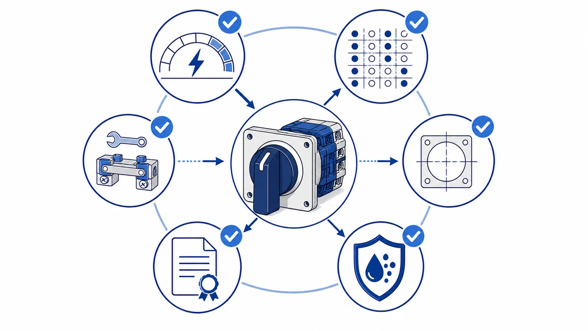
الشكل 4. يجب أن يتضمن الاستفسار الكامل التصنيف وتسلسل التلامس والتركيب والحاوية ومتطلبات المستند.
لماذا تم تصميم مفاتيح Shieldhz ذات الكامات الدوارة لهذه البيئات
Shieldhz هي العلامة التجارية التصديرية لشركة Zhejiang Shihe Electric Co. Ltd.، وهي شركة مصنعة تأسست في عام 2014 بمصنع مساحته أكثر من 5000 متر مربع، وأكثر من 100 موظف، ومعدات إنتاج لمكونات التحكم الصناعي. بالنسبة لتطبيقات مفاتيح الكامات الدوارة، لا تتعامل الشركة مع لوحات التحكم وأدوات الماكينات وخزانات التوزيع كنوع الطلب نفسه. كل بيئة تغير التصنيف، والمقبض، والتركيب، والحاوية، وفحوصات التوثيق.
بالنسبة للوحات التحكم، يراجع Shieldhz وظيفة الدائرة وتسلسل التلامس. بالنسبة لأدوات الماكينات، تضيف المراجعة وصول المشغل، والاهتزاز، ودورة التشغيل، وظروف الصيانة. بالنسبة لخزانات التوزيع، تركز المراجعة على دور العزل، ووضع العلامات، وتوجيه الموصلات، ووثائق الموافقة. يمكن للمشترين إرسال التطبيق، وبيانات التحميل، ورسم اللوحة، وحزمة الشهادات المستهدفة حتى يتمكن Shieldhz من التوصية بتكوين مدعوم بورقة البيانات.
الأسئلة الشائعة
ما هو الفرق بين فئتي الاستخدام AC-21A و AC-23A لمفاتيح الكامة الدوارة؟
يغطي AC-21A تبديل الأحمال المقاومة والحثية قليلاً، بينما AC-23A ينطبق على أحمال المحركات حيث يجب أن يقوم المفتاح بعمل وكسر تيارات حثي عند الجهد المقنن. يمكن أن يختلف التصنيف الحالي للمفتاح اختلافًا كبيرًا بين الفئتين، لذا تحقق دائمًا من الفئة مقابل حمولتك الفعلية قبل وضع المواصفات النهائية. يعد تطبيق مفتاح مصنّف AC-21A على دائرة المحرك أحد الأسباب الأكثر شيوعًا لفشل التلامس المبكر في إنشاءات لوحة التحكم.
هل يمكن استخدام مفتاح الكامة الدوار كجهاز عزل بموجب المواصفة القياسية IEC 60947-3؟
نعم، شريطة أن يكون المفتاح مصنفًا على وجه التحديد كفاصل أو مفصل مفاتيح بموجب المواصفة IEC 60947-3:2020+AMD1:2025، والتي تتطلب حدًا أدنى محددًا للفجوة الهوائية بين التلامسات المفتوحة وموضع الإغلاق الميكانيكي الذي يعطي ضمان عزل مرئي. لا تحمل جميع مفاتيح الكامات هذا التصنيف، لذا تأكد من ذلك في ورقة بيانات المنتج قبل استخدام أحدها لمهمة العزل. وعلى النقيض من ذلك، لا يتم تصنيف الملامس للعزل بموجب المواصفة IEC 60947-4-1 بغض النظر عن تصنيفه الحالي.
كم عدد دورات التشغيل التي يجب أن أتوقعها من مفتاح الكامات الدوارة الصناعية؟
التحمل الميكانيكي بموجب المواصفة IEC 60947-3 عادةً ما يتم تقييمه عند 20,000 إلى 50,000 دورة تشغيل بدون حمل، مع تطبيق الرقم الأدنى على المفاتيح المستخدمة تحت الحمل المقنن الكامل في مهمة تبديل المحرك AC-23A. الرقم الدقيق يعتمد على ورقة البيانات ويختلف حسب السلسلة والتصنيف الحالي. يجب جدولة التطبيقات ذات الدورة العالية مثل محددات عمود الدوران لأداة الماكينة لفحص التلامس قبل الوصول إلى حد الدورة المقدرة، وليس بعدها.
ما هو تصنيف IP المطلوب لمفتاح كاميرا مثبت في لوحة أداة الماكينة؟
إن IP54 هو الحد الأدنى المقبول عمومًا لقواطع لوحة أداة الماكينة، مما يوفر حماية ضد رذاذ سائل التبريد ودخول النتوءات. تتطلب البيئات التي تحتوي على رذاذ سائل التبريد المباشر أو الغسيل عالي الضغط IP65 أو أعلى. ينطبق تصنيف IP على مانع تسرب الواجهة الأمامية مقابل باب اللوحة، وليس فقط جسم المفتاح، لذا تحقق من تركيب الحشية وأجهزة التركيب بشكل صحيح للحفاظ على فئة الحماية المقدرة.
ما أهمية عدد الأعمدة عند اختيار مفتاح كاميرا دوارة؟
يجب أن يتطابق عدد الأقطاب مع طوبولوجيا النظام: قطبان للدوائر أحادية الطور، وثلاثة أقطاب للأنظمة غير المؤرضة ثلاثية الطور، وأربعة أقطاب عندما يجب أيضًا تبديل الموصل المحايد أو عزله. إن استخدام مفتاح ثلاثي الأقطاب في نظام يتطلب تبديلًا محايدًا يترك الموصل المحايد نشطًا أثناء العزل، وهو ما يمثل مشكلة تتعلق بالسلامة وانتهاكًا للكود في معظم الولايات القضائية. تأكد من ترتيبات تأريض النظام مع مهندس الكهرباء بالمشروع قبل الانتهاء من عد الأعمدة.
ما هو عزم الدوران الطرفي الصحيح لتوصيل أسلاك مفتاح كاميرا دوارة؟
يتم تحديد عزم الدوران الطرفي في ورقة بيانات الشركة المصنعة ويختلف حسب حجم الطرف الطرفي والمقطع العرضي للموصل. يعد تطبيق رقم عام دون التحقق من ورقة البيانات خطأً شائعًا في التركيب. الوصلات ذات عزم الدوران المنخفض هي السبب الرئيسي للتسخين المقاوم وفشل التلامس المبكر، ويجب إعادة التحقق من عزم الدوران في كل فترة صيانة مجدولة بسبب التدوير الحراري الذي يؤدي إلى فك الوصلات اللولبية بمرور الوقت.
كيف أعرف ما إذا كان مفتاح الكاميرا الدوارة بحاجة إلى الاستبدال بدلاً من الصيانة فقط؟
المؤشرات الميدانية الثلاثة التي تفضل الاستبدال على استمرار الخدمة هي: تنقر التلامس الذي يتجاوز الحد المقبول من الشركة المصنعة، ومقاومة التلامس التي تظل أعلى من الحد المقبول من الشركة المصنعة بعد التنظيف، والتلاعب المحوري لعمود المشغل بما يتجاوز الحد المحدد من الشركة المصنعة. تسمح تجميعات حاملة التلامس القابلة للاستبدال ميدانيًا، والمتوفرة في سلسلة LW28 و LW42، بتبديل المكونات المستهدفة دون إزالة المفتاح بالكامل من اللوحة، مما يقلل من وقت التعطل في بيئات الإنتاج.
شي، موكسي
يكتب شي، موكسي مقالات شيلدهز الفنية لمشتري التحكم الصناعي والمكونات الكهربائية، والتي تغطي مفاتيح الكامات الدوارة، ومفاتيح العازل، ومفاتيح فصل التيار المستمر الكهروضوئية، وأزرار الضغط، وأضواء المؤشر، والحاويات المقاومة للماء، والكتل الطرفية. تستند المقالات على خبرة شركة Zhejiang Shihe Electric Co., Ltd. في التصنيع والتصدير، مع التركيز العملي على اختيار الطراز وأوراق البيانات والرسومات والشهادات وتصنيفات IP وتفاصيل الاستفسار التي يجب على المشترين التأكد منها قبل الطلب.