مفتاح الكامة الدوارة للتحكم في المحرك هو مفتاح محدد متعدد المواضع يقوم بتوجيه التيار عبر مسارات دائرة محددة عن طريق تدوير قرص كامات دقيق التشكيل مقابل حاملات التلامس الثابتة. يبدأ التحجيم الصحيح بقاعدة واحدة: يجب أن يفي التيار التشغيلي المقنن للمفتاح بتيار الحمل الكامل للمحرك أو يتجاوزه في فئة الاستخدام المعمول بها - AC-23A لتبديل المحرك، وليس فئة AC-21A الأخف المستخدمة للأحمال المقاومة. إذا أخطأت في هذه الفئة فقد يتسارع تآكل التلامس بسرعة. تغطي هذه المقالة اختيار التصنيف الحالي، وتصنيف دورة التشغيل، وخيارات نوع المقبض، وتكوينات الأسلاك، وفترات الصيانة لمهندسي لوحات التحكم الصناعية، وبناة اللوحات، ومشتري مصنعي المعدات الأصلية الذين يحددون مفاتيح التبديل لدوائر المحركات ثلاثية الطور.
ما وظيفة مفتاح الحدبة الدوارة في دائرة المحرك
في لوحات التحكم في المحركات، يعمل مفتاح الكامة الدوارة كوسيلة أساسية لاختيار أوضاع التشغيل - إلى الأمام أو الخلف أو دلتا النجوم أو إيقاف التشغيل - دون الحاجة إلى ملامسات منفصلة لكل وظيفة. يشغّل كل وضع مثبت مجموعة جسور تلامس محددة، ويوجه التيار إلى أطراف المحرك في تسلسل محدد مسبقًا. وهذا يجعل المفتاح مدير الدائرة، وفي العديد من التركيبات، جهاز العزل المحلي.
المواصفة القياسية الحاكمة هي IEC 60947-3:2020+AMD1:2025، والتي تنطبق على المفاتيح والمفصلات ومفصلات المفاتيح ووحدات دمج الصمامات لدوائر التوزيع والدوائر الحركية، بجهد مقنن يصل إلى 1000 فولت تيار متردد أو 1500 فولت تيار مستمر. النص الكامل متاح من خلال متجر IEC الإلكتروني. للحصول على مقدمة أوسع حول كيفية ملاءمة مفاتيح الكامة لتصميم لوحة التحكم، فإن ما هو مفتاح الكاميرا الدوارة يغطي المرجع مبدأ التشغيل بالتفصيل.
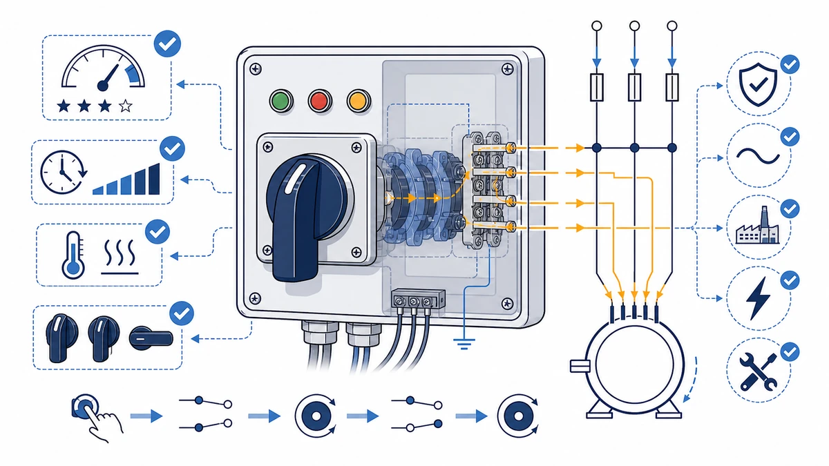
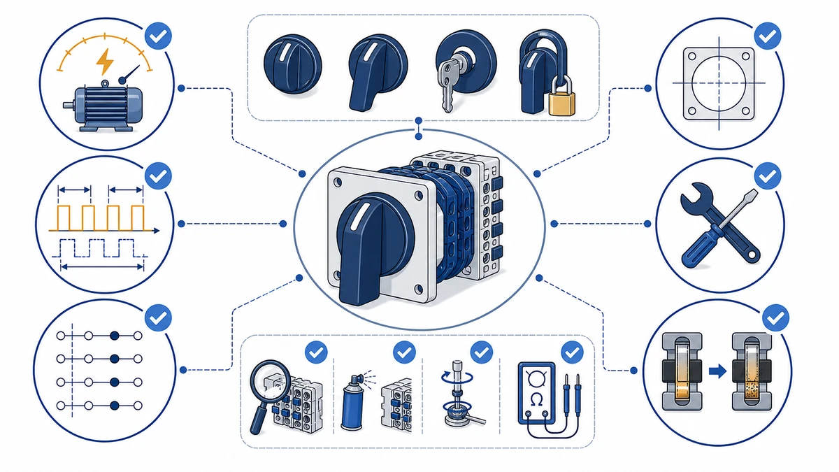
الشكل 1. المفهوم الأساسي وراء مفتاح الكامة الدوارة لاختيار التحكم في المحرك.
كيفية تحديد التصنيف الحالي الصحيح للتحكم في المحرك
لا تقم أبدًا بمطابقة تصنيف المفتاح مباشرة مع تيار لوحة المحرك. بموجب المواصفة القياسية IEC 60947-3، يندرج تبديل المحرك تحت فئة الاستخدام AC-23A، والتي تتطلب مفتاحًا مصنفًا لصنع وكسر تيارات أعلى بكثير من تيار الحمل الكامل للمحرك (FLC). سوف يتدهور المفتاح المحدد فقط في FLC تحت فئة AC-21A الأخف وزنًا في خدمة المحرك - وهو نمط فشل يشاهد عادةً عندما يستبدل منشئو اللوحات مفاتيح التبديل ذات الأغراض العامة بمفاتيح التبديل ذات الكامات المصنفة للمحرك.
لماذا يغير AC-23A حسابات التحجيم AC-23A
AC-23A هي فئة استخدام التيار المتردد الأكثر تطلبًا لمفاتيح الكامة. أثناء بدء تشغيل المحرك، يصل التيار المتدفق عادةً إلى 6 إلى 8 أضعاف FLC لبدء التشغيل المباشر على الخط. يتم اختبار المفتاح لعمل وكسر هذا النوع من التشغيل بدون لحام تلامسي غير مقبول أو تآكل القوس ضمن ظروفه المقدرة. بالنسبة لمفاتيح الكامة الدوارة المستخدمة في التحكم في المحرك، تتمثل ممارسة التحجيم القياسية في اختيار مفتاح يفي تياره المقنن AC-23A المقدر بـ FLC للمحرك أو يتجاوزه، مع الاستمرار في تطبيق أي منحنيات اشتقاق من الشركة المصنعة لدرجات الحرارة المحيطة وتهوية الضميمة وتردد التبديل وظروف التركيب.
جدول تحجيم تصنيف تصنيف المحرك من FLC إلى مفتاح التبديل (AC-23A، 400 فولت تيار متردد، 3 مراحل)
قوة المحرك (كيلوواط)
تقريبًا FLC (A)
الحد الأدنى. تصنيف المفتاح AC-23A (A)
السلسلة النموذجية
0.37
1.1
10
ل.و.28
0.75
1.9
10
ل.و.28
1.5
3.6
10
ل.و.28
2.2
5.0
10
ل.و.28
4.0
8.6
10
ل.و.28
5.5
11.5
16
LW28 / LW42
7.5
15.3
20
ل.و.42
11
22.0
25
ل.و.42
15
29.5
32
ل.و.42
22
43.0
50
ل.و.42
30
58.0
63
ل.و.42
قيم FLC تقريبية عند 400 فولت، عامل قدرة 0.85، كفاءة 0.9. تحقق دائمًا من لوحة اسم المحرك وجهد الإمداد المحلي.
تطبيق الجدول عملياً
بالنسبة لمحرك بقدرة 7.5 كيلوواط مع FLC حوالي 15.3 أمبير، فإن الحد الأدنى لتصنيف مفتاح AC-23A هو 20 أمبير. يضيف اختيار الحجم القياسي التالي - 25 أمبير - هامشًا عمليًا لتغير جهد الإمداد بزيادة أو نقصان 10% ودرجات الحرارة المحيطة التي تزيد عن 40 درجة مئوية. مفاتيح تبديل الكامات الدوارة من سلسلة LW42 تغطي النطاق من 16 أمبير إلى 63 أمبير، وهي مصنفة وفقًا للمواصفة IEC 60947-3 عند Ui 690 فولت تيار متردد، مما يجعلها مناسبة لنطاق تحجيم المحرك هذا دون الحاجة إلى تخفيف إضافي في العبوات الصناعية القياسية.
بالنسبة للمحركات التي تزيد عن 30 كيلو وات أو تطبيقات VFD، استشر متطلبات مفتاح العزل الخاصة بالشركة المصنعة للمحرك. يؤثر المحتوى التوافقي من جانب الخرج على معدلات التآكل التلامسي بشكل مختلف عن أحمال المحرك الجيبية، ولا يغطي تصنيف AC-23A الأشكال الموجية غير الجيبية في أطراف خرج المحرك.
للاطلاع على نظرة عامة على السلاسل المتاحة التي تغطي 10 أمبير حتى 63 أمبير، يمكن الاطلاع على مجموعة منتجات مفاتيح الكامات الدوارة نقطة بداية عملية لمطابقة سعة المفتاح مع متطلبات حمل المحرك.
الملاحظات الميدانية للتصنيف الحالي:
عند تشغيل المحرك على مصدر إمداد بجهد كهربائي معروف، قم بزيادة الحجم بمعدل قياسي واحد عن الحد الأدنى للجدول. يزيد ترهل الجهد من سحب التيار ويسرع من تسخين التلامس.
إذا كانت لوحة اسم المحرك تُظهر عامل خدمة أعلى من 1.0، فقم ببناء اختيارك للمفتاح على تيار عامل الخدمة (FLC مضروبًا في SF)، وليس FLC الأساسي.
بالنسبة للمحركات التي تغذيها VFD، ضع مفتاح الكامة على جانب الخط من المحرك، وليس على جانب الخرج.
أعد فحص عزم الدوران الطرفي بعد فترة التشغيل الأولية الموصى بها من قبل الشركة المصنعة أو إجراء الصيانة في الموقع. يمكن أن يؤدي التدوير الحراري أثناء الخدمة المبكرة إلى إرخاء أطراف اللولب بشكل أسرع من التشغيل في حالة مستقرة.
تصنيف دورة العمل وسبب تغييره لاختيار المفتاح الخاص بك
قد يتعامل المفتاح المصنّف بقدرة 20 أمبير متواصل مع تيار أقل بأمان فقط في ظل التدوير المتكرر لبدء التشغيل وإيقافه - لأن التراكم الحراري بين العمليات، وليس ذروة التيار وحدها، هو الذي يحدد طول عمر التلامس وسلامة العزل.
تحدد المواصفة القياسية IEC 60034-1 أنواع المهام التي تُعلم بشكل مباشر كيف يجب أن يعمل مفتاح الكامة مع مرور الوقت.
جدول مقارنة تصنيف الواجبات
نوع واجب IEC
التصنيف
الوصف
نموذجي في الوقت المحدد
الآثار المترتبة على تبديل الكاميرا
S1
مستمر
حمل ثابت لوقت كافٍ للوصول إلى التوازن الحراري
100%
ينطبق التيار المقدر الكامل؛ حدد المفتاح عند 100% من FLA المحرك
S2
وقت قصير
فترة تحميل ثابتة متبوعة بفترة راحة كافية للتبريد إلى درجة الحرارة المحيطة
10-60 دقيقة
إجهاد حراري معتدل؛ تحقق من بيانات الاستنقاص من الشركة المصنعة
S3
دورية متقطعة
دورات متماثلة متكررة من التحميل وعدم التحميل؛ لا يوجد توازن حراري
عادة 15-40% CDF 15-40%
تتسارع وتيرة تآكل التلامس؛ تأكد من عدد الدورات المقدرة مع ورقة البيانات
S4
دورية متقطعة مع بدء التشغيل
ظروف S3 بالإضافة إلى عابرات تيار البدء الكبيرة
15-40% CDF 15-40% مع تدفق
اختر المفتاح المخصص للتيار المتردد 23 أمبير؛ يمكن أن يصل التدفق الداخلي إلى 6-8 أضعاف FLA
بالنسبة للواجب S3 و S4، فإن عامل المدة الدورية (CDF) - معبراً عنه بوقت التشغيل مقسومًا على إجمالي زمن الدورة مضروبًا في 100% - هو المعامل الرئيسي. قد يفرض المحرك الذي يعمل عند 25% CDF بتيار حمولة كاملة 10 أمبير حمولة كاملة حملاً حرارياً مكافئاً على ملامسات المفتاح يتجاوز الرقم البسيط للوحة الاسم، بسبب أحداث التدفق المتكرر. ويعتمد عامل الاستنزاف الدقيق على سلسلة المفاتيح وتردد الدورة؛ تأكد من ذلك مقابل منحنيات الاستنزاف المنشورة من الشركة المصنعة بدلاً من تطبيق نسبة مئوية عامة.
في أنظمة النقل، وخطوط التعبئة والتغليف، ودوائر رافعات الرافعات، يكون التشغيل S4 هو القاعدة وليس الاستثناء. يؤدي تحديد مفتاح كاميرا دوّارة مصنفة فقط للخدمة المستمرة S1 في هذه البيئات إلى تنقر التلامس في غضون أشهر بدلاً من سنوات.
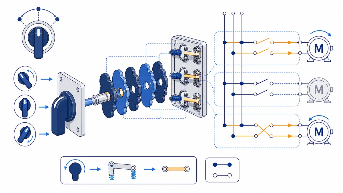
الشكل 2. يجب أن تربط فحوصات الاختيار الحمل وتسلسل التحويل والحاوية ومتطلبات التوثيق.
الملاحظات الميدانية لدورة العمل:
في الرافعة الرافعة ومحركات الجر، احسب كل هرولة كحدث تبديل كامل عند تقدير عدد الدورات السنوية - يكون التدفق الداخلي متطابقًا بغض النظر عن مدة التشغيل.
إذا كان التطبيق ينطوي على التوصيل (عكس المحرك مع استمرار دورانه لكبحه)، تعامل معه كحد أدنى للخدمة S4 وتأكد من القدرة الميكانيكية المقدرة للمفتاح مع فريق هندسة Shieldhz قبل تحديد المواصفات.
في بيئات التخزين الباردة، تحقق من أن نطاق درجة الحرارة المقدرة للمفتاح يمتد إلى الحد الأدنى للتركيب؛ بعض مفاتيح الكامات تنخفض درجة حرارتها إلى أقل من 5 درجات مئوية تحت الصفر.
اختيار نوع المقبض: مطابقة المقبض مع التطبيق
يؤثر نوع المقبض على مفتاح الكامة الدوارة بشكل مباشر على سلامة المشغل، والتحكم في الوصول، والملاءمة المريحة. يمكن أن يؤدي اختيار المقبض الخاطئ إلى مخاطر التشغيل غير المصرح به أو بطء الاستجابة للطوارئ.
مقارنة نوع المقبض
نوع المقبض
عزم الدوران التشغيلي النموذجي
التحكم في الوصول
سياق التطبيق الموصى به
مقبض (دائري/بيضاوي)
ارجع إلى ورقة البيانات
لا يوجد
لوحات التحكم ذات الأغراض العامة، والدوائر المساعدة منخفضة المخاطر
مقبض مسدس/رافعة مسدس
ارجع إلى ورقة البيانات
لا يوجد
تشغيل صناعي عالي الدورة، وتشغيل القفازات، ولوحات أدوات الماكينات
قفل المفتاح
ارجع إلى ورقة البيانات
إزالة المفتاح في أي موضع
المعدات ذات الوصول المقيد، والبيئات متعددة المشغلين، والتدفئة والتهوية وتكييف الهواء
قابل للقفل
ارجع إلى ورقة البيانات
قفل قفل القفل
الامتثال لـ LOTO وفقًا للمواصفة IEC 60204-1، عزل الصيانة
تختلف قيم عزم الدوران التشغيلي حسب السلسلة وتكوين كتلة التلامس؛ تأكد دائمًا من ورقة بيانات السلسلة ذات الصلة بدلاً من الاعتماد على النطاقات العامة.
بالنسبة للوحات التحكم في المحرك القياسية، يوفر مقبض المقبض أقل مقاومة تشغيل وأسرع استجابة. في البيئات التي يرتدي فيها المشغلون قفازات ثقيلة، توفر قبضة المسدس ميزة ميكانيكية أكثر أمانًا. تتناسب مقابض القفل بالمفتاح مع الدوائر التي يجب أن تظل في حالة محددة بين النوبات. بالنسبة لعزل الصيانة، غالبًا ما يكون المقبض القابل للقفل مطلوبًا بموجب إجراءات LOTO الخاصة بالموقع وممارسات سلامة الماكينة؛ تأكد من متطلبات IEC 60204-1 المعمول بها أو المتطلبات المحلية للماكينة المحددة. إن سلسلة مفاتيح الكامات الدوارة LW28 وسلسلة LW42 كلاهما يوفران خيارات مقبض قابل للقفل لدعم إجراءات LOTO.
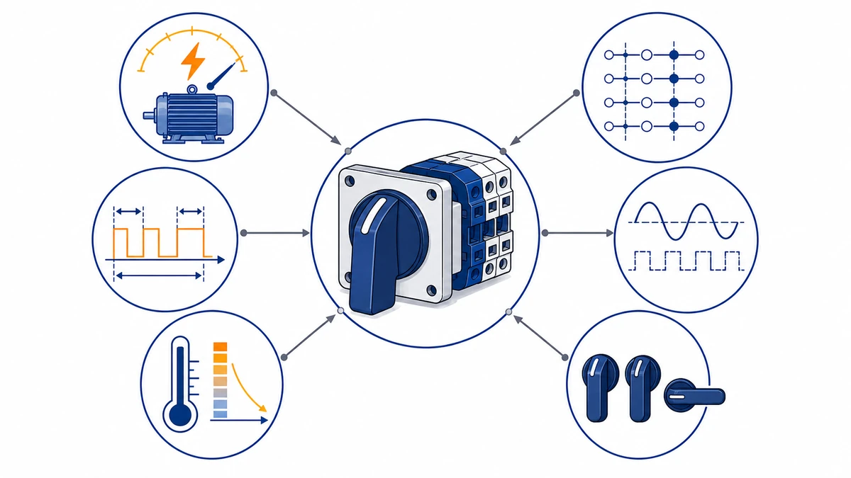
الشكل 3. يجب التحقق من سياق الأسلاك التطبيقية بالمقارنة مع مخطط التلامس الخاص بالشركة المصنعة قبل التنشيط.
تكوينات الأسلاك لتطبيقات التحكم في المحركات الشائعة
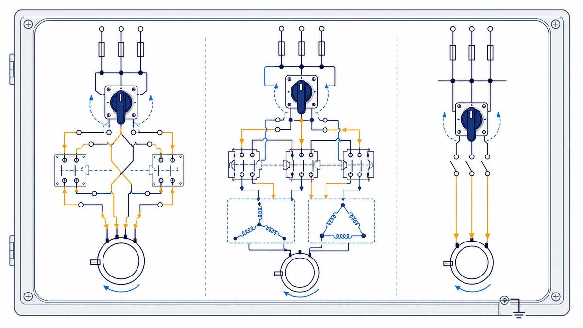
تضع التكوينات الثلاثة الأكثر شيوعًا لأسلاك التحكم في المحرك - التشغيل الأمامي/العاكس، والتشغيل على شكل نجمي-دلتا، والعزل المباشر على الخط - كل منها يضع متطلبات مختلفة على عدد التلامسات، وتسلسل التبديل، والتصنيف الحالي.
التكوين الأمامي/الخلفي
يستخدم مفتاح الكامة الأمامي/الخلفي ثلاثة أوضاع: أمامي - إيقاف - عكسي. يقوم تسلسل قرص الكامة بعكس مرحلتين من مراحل الإمداد الثلاث (L1 وL3) بين الوضعين الأمامي والخلفي بينما يفتح إيقاف التشغيل جميع الأقطاب في وقت واحد. يتطلب ذلك ستة ملامسات على الأقل مرتبة في مجموعتي تبديل مستقلتين، مصنفة AC-23A عند تيار الحمل الكامل للمحرك. بالنسبة لمحرك بقوة 7.5 كيلوواط عند 400 فولت تيار متردد 400 فولت تيار متردد يسحب حوالي 15 أمبير، قد يكون مفتاح كاميرا بقدرة 20 أمبير AC-23A المصنف مرشحًا، ولكن الاختيار النهائي لا يزال يعتمد على تصنيف ورقة البيانات ومشتقات المحيط ودرجة حرارة الضميمة وتردد التحويل.
تحقق من مخطط التلامس في ورقة بيانات السلسلة قبل توصيل الأسلاك. يؤكد المخطط على الملامسات التي يتم إغلاقها عند كل موضع من مواضع التلامس ويمنع أخطاء الأسلاك التي قد تتسبب في حدوث قصور من طور إلى طور أثناء انتقالات الموضع.
تكوين بدء تشغيل نجمة-دلتا
يقلل بدء التشغيل بنجمة-دلتا من تيار التدفق عن طريق توصيل لفات المحرك أولاً بنجمة (Y)، ثم التحول إلى دلتا بمجرد اقتراب المحرك من سرعة التشغيل. يجب أن يتحكم مفتاح الكامة في ثلاثة ملامسات منفصلة - الرئيسية والنجمة والدلتا - من خلال تسلسل زمني. ويتطلب ذلك عادةً مفتاح كامات من 8 إلى 12 ملامسًا مع ملف تعريف كامات يمنع إغلاق ملامس النجمة ودلتا في وقت واحد. يجب أن يفتح موضع السكون الانتقالي ملامسات النجمة قبل إغلاق ملامسات دلتا. قم بتأكيد تسلسل الانقطاع قبل الإغلاق في مخطط ملف تعريف الكامة المرفق مع ورقة بيانات المفتاح قبل التشغيل.
تكوين معزل DOL
في تطبيق العازل المباشر على الخط، يعمل مفتاح الكامة الدوار كعازل للمحرك وفقًا للمواصفة IEC 60947-3، مما يوفر حالة إيقاف تشغيل مرئية للوصول الآمن للصيانة. يحمل المفتاح تيار المحرك بالكامل بشكل مستمر ويجب أن يكون مصنّفًا لتيار AC-23A عند تيار الحمل الكامل للمحرك. يعد مفتاح الكامة ثلاثي الأقطاب هو الاختيار القياسي للمحركات ثلاثية الطور؛ تأكد من تصنيف مفصل المفتاح في ورقة البيانات إذا كان المفتاح مخصصًا ليكون بمثابة نقطة العزل الوحيدة.
بالنسبة لمنشئي اللوحات الذين يعملون في جميع التكوينات الثلاثة، توفر سلسلة LW42 مجموعات كتل التلامس المعيارية التي تدعم تسلسلات التبديل المخصصة دون إعادة توصيل الوحدة الأساسية.
قائمة التحقق من اختيار مفتاح الكامات
الخطوة 1 - تحديد تيار الحمل الكامل للمحرك
اقرأ لوحة اسم المحرك FLC. إذا كان المحرك يحتوي على عامل خدمة أعلى من 1.0، اضرب FLC في عامل الخدمة للحصول على التيار التصميمي. قم بالتقريب إلى تصنيف المفتاح القياسي التالي.
الخطوة 2 - تأكيد فئة الاستخدام
حدد نوع الحمولة. الأحمال المقاومة أو الاستقرائية الخفيفة تستخدم AC-21A؛ أما تبديل المحرك فيستخدم AC-23A. اختيار AC-21A لدائرة المحرك هو خطأ شائع في المواصفات يؤدي إلى تآكل التلامس المبكر.
الخطوة 3 - تعيين فئة الواجب
طابق تردد التشغيل مع فئة العمل. التدوير المتقطع أو العكسي العرضي يناسب العمل القياسي. يتطلب التدوير المستمر أو مهمة التوصيل المستمر مفتاح كامات ذو قدرة تحمل ميكانيكية أعلى - تأكد من تصنيف عدد الدورات مع الشركة المصنعة لتطبيقات S3 و S4.
الخطوة 4 - اختر نوع المقبض وتنسيق التركيب
تغطي التنسيقات الشائعة لتركيب اللوحة العديد من تصميمات اللوحة، ولكن رسم المفتاح المحدد يتحكم في متطلبات القطع النهائي والتشغيل الآلي. المقابض القابلة للقفل مطلوبة حيثما تنطبق إجراءات LOTO. بالنسبة للبيئات الخارجية أو بيئات الغسيل، تحقق من تصنيف IP قبل الانتهاء من الاختيار.
الخطوة 5 - تحقق من ملاءمة السلسلة وتأكد من ذلك مع الهندسة
ويغطي الموديل LW28 التطبيقات المدمجة حتى 20 أمبير، بينما يناسب الموديل LW42 اللوحات الصناعية ذات التيار العالي حتى 63 أمبير. سلسلة SH30 يضيف حماية الضميمة المقدرة. قبل تقديم طلب الشراء، اطلب ورقة بيانات السلسلة من Shieldhz وقم بمقارنة تصنيف AC-23A، وUi، والتحمل الميكانيكي، ومخطط التلامس مع معلمات دائرة المحرك. هذه الخطوة مهمة بشكل خاص بالنسبة لتكوينات S4 ذات المهام وتكوينات دلتا النجمية حيث يكون تسلسل التلامس أمرًا بالغ الأهمية للسلامة.
تحقق من أن أبعاد فتحة اللوحة تتطابق مع جسم المفتاح وأن سطح التركيب مسطح لتجنب إجهاد المبيت.
قم بضبط عزم دوران البراغي الطرفية حسب القيمة المحددة من الشركة المصنعة باستخدام مفك عزم دوران معاير. الوصلات ذات عزم الدوران المنخفض هي السبب الرئيسي للتسخين المقاوم في الكتلة الطرفية.
تأكد من أن مقبض التشغيل يزيل المكونات المجاورة في جميع أوضاع الدوران.
قم بتسمية كل موضع تبديل بوضوح على وجه اللوحة. يؤدي وضع الملصقات الغامضة إلى قيام المشغلين بالتبديل تحت الحمل في مواضع غير صحيحة، مما يسرع من تآكل التلامس.
قم بتسجيل تاريخ التركيب وقيم عزم الدوران الأولي للطرف في سجل صيانة اللوحة للرجوع إليها في المستقبل.
فترات الفحص الدوري
كل 6 أشهر: افحص عزم الدوران الطرفي، وافحص بحثًا عن تغير اللون أو علامات الحرارة، وتحقق من أن حركة المقبض واضحة دون وجود مواضع وسيطة.
كل 12 شهرًا: افحص أسطح التلامس بحثًا عن وجود تنقر أو ترسبات كربونية؛ قم بقياس مقاومة التلامس وقارن بخط الأساس المسجل عند التركيب. يشير ارتفاع قيم المقاومة إلى تدهور السطح قبل ظهور التلف المرئي.
في فترة التحمل الميكانيكية المقدرة من الشركة المصنعة أو أثناء الإصلاح الشامل المخطط له: ضع في اعتبارك استبدال كتلة التلامس في التطبيقات عالية الدورة مثل بادئات التشغيل العكسية أو نجمية الدلتا.
أنماط الفشل الشائعة
تنقر التلامس والتآكل - ناتج عن التبديل المتكرر لأحمال المحرك الاستقرائي. افحص واجهات التلامس بحثًا عن وجود حفر تشبه الحفر؛ استبدل كتل التلامس عندما يكون عمق الحفرة واضحًا بصريًا أو عندما ترتفع مقاومة التلامس بشكل ملحوظ فوق خط أساس التركيب.
التوصيلات الطرفية المفكوكة - يؤدي التدوير الحراري إلى ارتخاء الأطراف اللولبية بمرور الوقت. يمكن للوصلة التي تقاس بمقاومة منخفضة عند التركيب أن ترتفع مقاومتها بشكل كبير بعد أشهر من التشغيل دون إعادة ربطها بالبراغي، مما يولد حرارة موضعية تؤدي إلى تدهور العزل والأسلاك المجاورة.
تآكل قرص الكامة وفقدان البطارية - في التطبيقات ذات الدورة العالية، يتآكل ملف تعريف الكامة عند مفارق المواضع، مما يتسبب في استراحة المفتاح بين المواضع. يمكن اكتشاف ذلك كنقرة ناعمة أو غائبة أثناء الدوران ويجب تصحيحها على الفور، حيث يمكن أن يؤدي الوضع الوسيط إلى إنشاء دائرة جزئية غير مقصودة.
بالنسبة لمفاتيح سلسلة LW28 وسلسلة LW42، تتوفر وحدات التلامس البديلة كمكونات منفصلة، بحيث يمكن تبديل كتلة التلامس البالية دون استبدال جسم المفتاح بالكامل.
الشكل 4. يجب أن يتضمن الاستفسار الكامل التصنيف وتسلسل التلامس والتركيب والحاوية ومتطلبات المستند.
كيف يقوم Shieldhz بتحديد مقاسات مفاتيح كامات التحكم في المحرك
بالنسبة للاستفسارات المتعلقة بالتحكم في المحرك، يبدأ Shieldhz بلوحة اسم المحرك وطريقة بدء التشغيل، وليس فقط التيار الاسمي. يتحقق الفريق مما إذا كان المفتاح مستخدمًا للتحكم في التشغيل والإيقاف، أو للأمام/الإيقاف/الانعكاس، أو منطق دلتا النجوم، أو اختيار المصدر، أو عزل الخدمة، ثم يراجع بيانات AC-23A أو AC-3 حيثما أمكن، وتردد التبديل، ودرجة الحرارة المحيطة، وحالة الضميمة، ومتطلبات المقبض، وتوقعات الإغلاق.
تتضمن تفاصيل الاستفسار المفيدة قوة المحرك، وتيار الحمل الكامل، وجهد الخط، وعدد الأطوار، وطريقة البدء، والعمليات المتوقعة في اليوم، وحدود قطع اللوحة، والوثائق المطلوبة. يمكن لـ Shieldhz بعد ذلك تأكيد ما إذا كان مفتاح الكاميرا الدوارة مناسبًا، وما إذا كان يجب أن يبقى موصل أو مرحل وقائي في الدائرة، وأي رسم/جدول اتصال يجب استخدامه في البناء.
الأسئلة الشائعة
ما هو الفرق بين فئتي الاستخدام AC-21A و AC-23A لمفاتيح الكامة الدوارة؟
يغطي المفتاح AC-21A تبديل الأحمال المقاومة والحثية قليلاً، في حين أن المفتاح AC-23A مصمم خصيصًا لأحمال المحركات حيث يمكن أن تصل تيارات التدفق إلى 6 إلى 8 أضعاف قيمة الحمل الكامل. يؤدي استخدام المفتاح المقنن AC-21A في دائرة المحرك إلى تآكل التلامس المتسارع لأن المفتاح لم يتم تصميمه لصنع وكسر التيارات الاستقرائية الأعلى المتضمنة. تأكد دائمًا من فئة الاستخدام في ورقة بيانات السلسلة قبل تحديد المواصفات.
هل يمكن استخدام مفتاح الكامة الدوارة كجهاز عزل وحيد للمحرك؟
نعم، شريطة أن يفي المفتاح بمتطلبات المواصفة IEC 60947-3 كمفصل-مفتاح، والذي يتطلب فجوة عزل محددة خارج الحالة ومقبض قابل للقفل للامتثال لـ LOTO. لا تحمل جميع مفاتيح الكامة تصنيف مفصل-مفتاح - تحقق من ورقة بيانات السلسلة التي تؤكد ذلك قبل استخدام المفتاح كنقطة العزل الوحيدة.
كيف يمكنني تحديد حجم مفتاح الكامة الدوارة لبادئ تشغيل محرك دلتا نجمي؟
قم بتحديد حجم المفتاح بناءً على تيار الحمل الكامل للمحرك في حالة دلتا (قيد التشغيل)، وليس التيار النجمي المخفض. يجب أن يمنع تكوين كتلة التلامس أيضًا الإغلاق النجمي والدلتاوي المتزامن، لذا تأكد من أن ملف تعريف الكامة يوفر انتقالًا قبل الانقطاع بين تلك المواضع. راجع مخطط التلامس في ورقة البيانات واطلب من فريق هندسة Shieldhz التأكد من التكوين قبل التوصيل.
ماذا يحدث إذا قمت باختيار مفتاح كامات تصنيفه أقل من تيار الدوار المقفل للمحرك؟
ستحاول ملامسات المفتاح عمل أو كسر تيار غير مصنفة له، مما يتسبب في حدوث لحام تلامسي أو تآكل شديد في القوس الكهربائي أو كليهما. ويظهر ذلك عملياً على شكل مفتاح يصبح من الصعب تدويره أو يفشل في الفتح بشكل نظيف - وكلا الحالتين تخلق خطراً على السلامة وتتطلب الاستبدال الفوري.
هل تؤثر درجة الحرارة المحيطة على التصنيف الحالي لمفتاح الكاميرا الدوارة؟
نعم. يتم تصنيف معظم مفاتيح الكامات عند درجة حرارة محيطة مرجعية تبلغ 40 درجة مئوية؛ وفوق درجة الحرارة هذه، تنخفض قدرة تيار التلامس بسبب انخفاض تبديد الحرارة. بالنسبة للتركيبات في العبوات ذات التهوية الضعيفة أو البيئات المحيطة العالية، قم بتطبيق منحنى الاستنقاص الخاص بالشركة المصنعة أو حدد التصنيف القياسي التالي أعلى من الحد الأدنى المحسوب. قيم الاستبعاد المحددة تعتمد على السلسلة ويجب أخذها من ورقة البيانات المنشورة.
كم مرة يجب فحص تلامس مفاتيح الكامة الدوارة في تطبيقات المحركات عالية الدورة؟
بالنسبة للتطبيقات التي تعمل لأكثر من 8 ساعات يوميًا مع بدء التشغيل المتكرر، يعتبر الفحص البصري لمدة 6 أشهر وفحص عزم الدوران الطرفي خط أساس عملي. ويساعد القياس السنوي لمقاومة التلامس واستبدال كتلة التلامس وفقًا لتصنيف التحمل الخاص بالشركة المصنعة أو خطة صيانة الموقع على إبقاء المفتاح ضمن غلاف الأداء المقدر له.
هل لا يزال مرحل حماية المحرك المنفصل مطلوبًا عند استخدام مفتاح كاميرا دوارة؟
يتعامل مفتاح الكامة الدوارة مع تبديل الدائرة وعزلها ولكنه لا يوفر حماية من الحمل الزائد أو الدائرة القصيرة. يجب تضمين مرحل حماية المحرك أو مرحل الحمل الزائد الحراري في الدائرة لحماية لفات المحرك من التيار الزائد المستمر. يعمل مفتاح الكامة وجهاز الحماية بوظائف تكميلية، وليست قابلة للتبديل - فكلاهما مطلوب في دائرة التحكم في المحرك المصممة بشكل صحيح.
شي، موكسي
يكتب شي، موكسي مقالات شيلدهز الفنية لمشتري التحكم الصناعي والمكونات الكهربائية، والتي تغطي مفاتيح الكامات الدوارة، ومفاتيح العازل، ومفاتيح فصل التيار المستمر الكهروضوئية، وأزرار الضغط، وأضواء المؤشر، والحاويات المقاومة للماء، والكتل الطرفية. تستند المقالات على خبرة شركة Zhejiang Shihe Electric Co., Ltd. في التصنيع والتصدير، مع التركيز العملي على اختيار الطراز وأوراق البيانات والرسومات والشهادات وتصنيفات IP وتفاصيل الاستفسار التي يجب على المشترين التأكد منها قبل الطلب.