العنوان
304 شارع شمال كاردينال 304.
مركز دورشيستر، ماساتشوستس، ماساتشوستس 02124
ساعات العمل
من الاثنين إلى الجمعة: 7 صباحاً - 7 مساءً
عطلة نهاية الأسبوع 10 صباحاً - 5 مساءً
العنوان
304 شارع شمال كاردينال 304.
مركز دورشيستر، ماساتشوستس، ماساتشوستس 02124
ساعات العمل
من الاثنين إلى الجمعة: 7 صباحاً - 7 مساءً
عطلة نهاية الأسبوع 10 صباحاً - 5 مساءً
احصل على المفاتيح الدوارة الممتازة والعوازل ومكونات اللوحة مباشرة من الشركة المصنعة.
املأ النموذج أدناه للحصول على الأسعار والكتالوجات والدعم الفني.
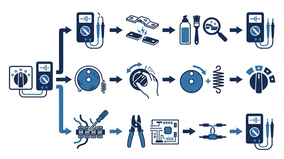
تعرّف على مواضع مفاتيح الكامة الدوارة وأقطابها ومراحل التلامس، بالإضافة إلى فحوصات مخطط التلامس والتحقق من الأسلاك وملاحظات اختيار المشتري.
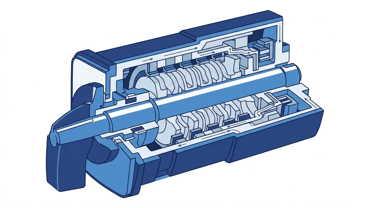
A rotary cam switch controls multiple circuit paths through a single actuator by rotating precision-machined cam discs against stacked contact carriers. Three parameters define what any given switch can do: positions (the number of detent stops), poles (the number of independent circuits switched simultaneously), and contact stages (the number of stacked contact modules on the shaft). Getting these three parameters right before ordering is the difference between a panel that works first time and one that requires a costly redesign. This article explains each parameter, shows how to read a contact chart, walks through common configurations, and gives you a practical checklist for selection, wiring, and procurement.
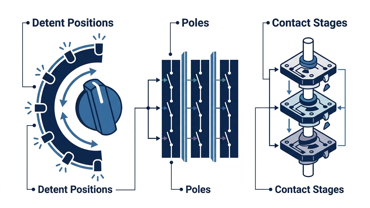
These three terms are distinct and frequently confused in specifications and purchase orders.
المناصب are the discrete detent stops the actuator shaft can occupy. A 3-position switch has three mechanically stable states, each held by a spring-loaded detent. Common position counts are 2, 3, 4, 6, 8, and 12, with angular increments of 30, 45, or 60 degrees between stops depending on the switch series. The exact angular spacing and total rotation arc for a given model must be confirmed from the manufacturer datasheet.
الأعمدة are the number of electrically independent circuits the switch controls in a single mechanical operation. A 4-pole switch opens or closes four separate circuit paths simultaneously. Each pole has its own contact bridge and is electrically isolated from adjacent poles. Rated insulation voltage between poles is a datasheet value — do not assume it from the series name alone.
Contact stages (also called contact layers or decks) are the individual cam disc and contact carrier assemblies stacked axially along the shaft. Each stage contains one set of contact bridges per pole. Stacking multiple stages allows each stage to carry a unique cam lobe profile, so different circuits can open and close in different sequences across the same set of positions. A single stage typically handles one or two poles; a multi-stage assembly can manage a larger number of independent contact pairs.
A useful way to hold the distinction: positions describe the actuator, poles describe the electrical width of a single switching event, and contact stages describe the mechanical depth of the switch assembly.
For a practical introduction to how these switches are constructed and applied, see What Is a Rotary Cam Switch.
Each cam disc is a hardened profile mounted coaxially on the actuator shaft. Raised lobes and recessed valleys on the disc correspond directly to the open and closed state of the contact bridge at each position. When a lobe bears against a contact carrier, it lifts the contact bridge away from its fixed counterpart, opening that pole. When the shaft rotates to place a valley under the carrier, the spring drives the bridge closed.
Stacking multiple cam discs along the same shaft — each with a unique lobe profile — is what gives a rotary cam switch its ability to sequence different circuits at different positions. This is a critical requirement in star-delta motor starters and reversing contactor circuits, where specific poles must open before others close to prevent a phase short circuit. The contact chart supplied by the manufacturer encodes exactly which poles are open or closed at each position, and matching that chart to your circuit’s switching requirements is the fundamental step in correct specification.
Contact resistance across a properly wiped silver-alloy bridge is a datasheet value that should be confirmed before specifying the switch for low-signal or sensitive control circuits. If cam profile wear allows incomplete contact closure, resistance rises and circuit behavior becomes unreliable. Inspect contact bridges at the maintenance intervals specified in the product documentation.
IEC 60947-3:2020+AMD1:2025 applies to switches, disconnectors, switch-disconnectors, and fuse-combination units for distribution and motor circuits, with rated voltage up to 1000 V AC or 1500 V DC. The standard sets requirements for rated insulation voltage, making and breaking capacity, and mechanical endurance. The current consolidated edition is available directly from the IEC webstore. For a plain-language summary of how the standard applies to cam switch selection, see What Is IEC 60947-3.
Practical notes for cam mechanism maintenance:
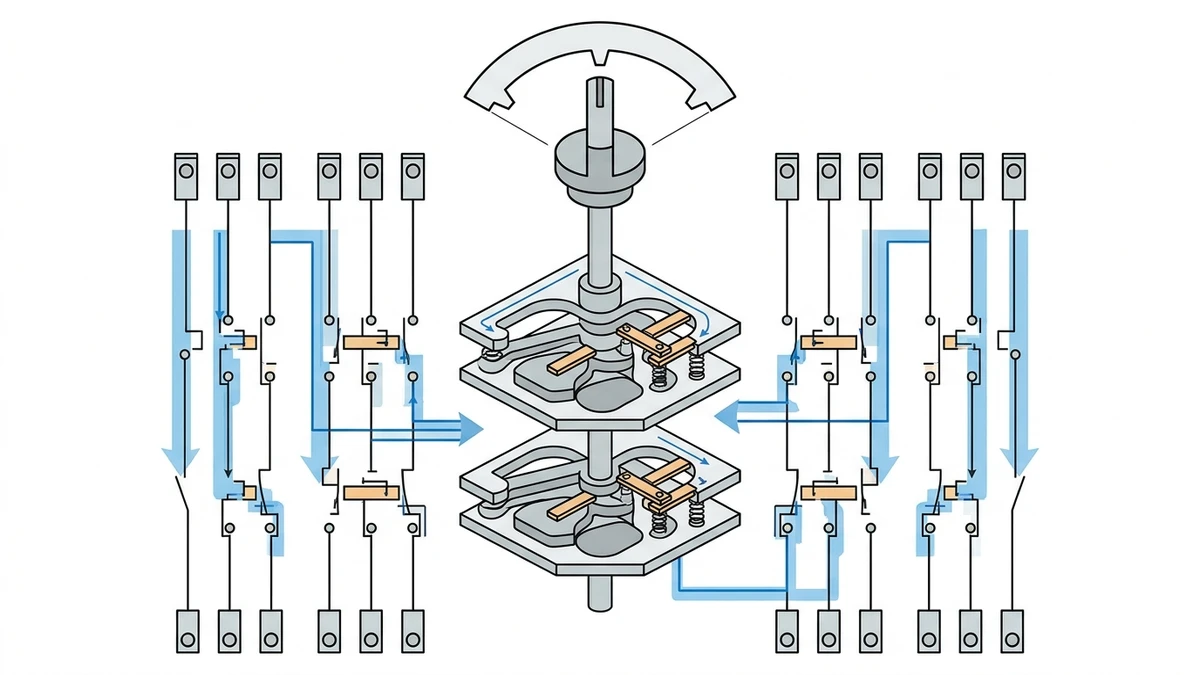
The three parameters are independent and can be combined in a wide range of configurations. A single switch can be, for example, 4-pole, 3-position, 2-stage — meaning it controls four circuits, across three selector positions, using two stacked contact decks. In motor control applications, this architecture is commonly used to implement star-delta starting sequences or forward-reverse interlocking without external relays.
The table below summarizes the parameters and their typical ranges. Confirm exact limits from the datasheet for the specific series you are specifying.
| المعلمة | What It Describes | Typical Range | Example |
|---|---|---|---|
| الأعمدة | Independent circuits switched simultaneously | 1 to 12 | 4-pole: controls L1, L2, L3, neutral |
| المناصب | Discrete detent stops | 2 to 12 | 3-position: OFF / Forward / Reverse |
| Contact Stages | Stacked contact modules on shaft | 1 to 6 | 2-stage: two contact layers per position |
إن LW28 series rotary cam switch supports modular cam stacks that allow custom contact sequences to be built from standard components. Confirm the available pole, position, and stage combinations for your target configuration with Shieldhz engineering before finalizing the bill of materials.
The contact chart is the primary document for verifying that a switch will perform the switching sequence your circuit requires. Misreading a single cell can create a phase-to-phase fault path, so this step is not optional.
The chart is a grid. Columns represent switch positions, typically numbered 0 through the maximum position count or labeled by function such as OFF, I, II, III. Rows represent individual contact pairs, grouped by pole. A 4-pole switch with 3 positions produces a grid of at least 4 rows by 3 columns.
Many contact diagrams use odd-numbered terminals for incoming conductors and even-numbered terminals for outgoing conductors, such as 1-2, 3-4, 5-6, and 7-8 contact pairs. Confirm the numbering convention used in the specific datasheet before wiring, because some manufacturers and custom cam stacks use alternative schemes.
A filled symbol in a cell — typically a filled circle, solid bar, or X depending on the manufacturer’s legend — means the contact bridge is closed and current can flow between the two terminals of that pole at that position. An empty cell means the contact is open. Always check the legend before interpreting; do not assume the convention.
For a 3-position selector switch controlling a reversing motor starter, a typical chart shows contacts for the forward direction closed only in position I, contacts for the reverse direction closed only in position III, and all contacts open in position 0. That pattern directly encodes the forward-off-reverse logic.
Step 1: List every switching event your circuit requires at each position.
Step 2: Map each event to a row-column cell in the chart.
Step 3: Confirm that no two mutually exclusive contacts are closed simultaneously. This is the most common source of short-circuit risk in motor control applications.
Step 4: For circuits requiring break-before-make sequencing, check the cam schematic for the angular gap between the opening and closing events. A gap that is too narrow should be confirmed with a slow-rotation continuity test before energizing. The minimum acceptable gap is a datasheet value — do not assume a figure.
Practical verification notes:
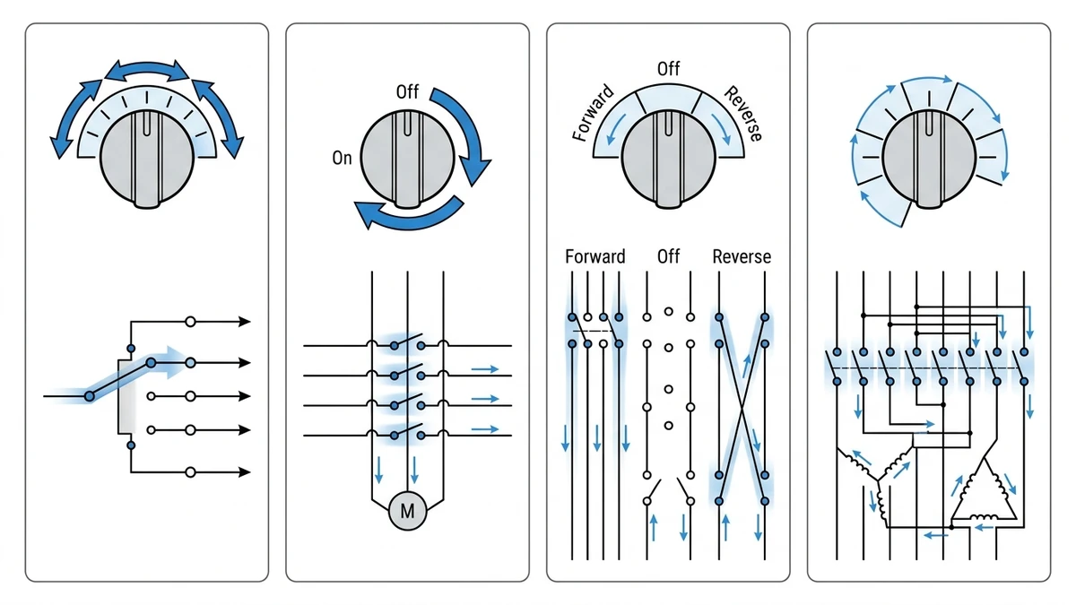
A 1-pole, multi-position cam switch suits signal selection and indicator lamp circuits in low-current control panels. It routes a single circuit to one of several outputs. This configuration is used for test point selection, mode annunciation, and HMI input switching where contact current is low. Confirm the rated current and voltage from the datasheet for the specific series.
Three-pole, 2-position switches are the standard format for direct-on-line motor starters. All three phases switch simultaneously. This configuration provides a defined off-state that allows safe panel access when the switch carries the appropriate IEC 60947-3 disconnector rating. Confirm the utilization category — for example, AC-23A for motor switching loads — from the datasheet before specifying.
A 4-pole, 3-position switch handles forward-off-reverse sequencing by reconfiguring phase connections across positions. Two poles swap phase order while the remaining poles handle neutral or auxiliary contacts. This is one of the most specified configurations in conveyor, pump, and fan control panels. Confirm the rated insulation voltage and mechanical endurance for the specific series from the datasheet.
Six-pole configurations support star-delta starting sequences, stepping through star connection, transition, and delta connection positions. This limits inrush current relative to direct-on-line starting. For multi-speed motors, additional positions reconfigure winding connections at each speed step. The LW42 series addresses higher-pole-count applications with contact stages rated for resistive and inductive load categories. Confirm the available configurations and ratings with Shieldhz engineering for your specific motor application.
Step 1 — Isolate the circuit. Confirm the supply is de-energized and locked out. Verify with a calibrated voltage tester rated for the circuit voltage.
Step 2 — Cross-reference the diagram. Identify which terminals carry the supply feed and which connect to load circuits for each position. Do this before touching any conductors.
Step 3 — Land supply conductors. Connect incoming supply lines to odd-numbered input terminals. Conductor cross-section must be sized to the switch’s rated current. Confirm the acceptable conductor size range from the datasheet.
Step 4 — Land load conductors. Connect output conductors to even-numbered terminals per the diagram. In multi-position switches, different output terminals activate at different positions, so each load circuit must be traced individually through the contact chart.
Step 5 — Verify torque and continuity. Tighten terminal screws to the torque value specified in the product documentation. Rotate through each position and confirm that contacts shown as closed in the chart are live and contacts shown as open are isolated.
Transposing input and output terminals is the most frequent error. It creates a dead circuit in every position and is easy to miss without a systematic terminal-by-terminal check.
Wiring to the wrong stage on a multi-stage switch is the second most common error. Physical stage order on the shaft does not always match the diagram numbering. Mark each stage before wiring.
Skipping the continuity check at every position before energizing is a procedural shortcut that causes field failures. The check takes a few minutes and catches the majority of wiring errors before they become fault events.
Before placing an order, confirm the following from the datasheet or with Shieldhz engineering:
For complex configurations — multi-speed motors, star-delta starters, or applications with mixed load types on different poles — request written confirmation from Shieldhz engineering that the specified cam stack matches your required contact sequence. The full Shieldhz rotary cam switch range covers standard and application-specific configurations.
The most common cause is contact surface oxidation or carbon buildup from repeated arcing on inductive loads. Inspect contact bridges under magnification. Clean with isopropyl alcohol if oxidation is light. Replace the contact stage assembly if silver plating is fully eroded or pitting is visible. Confirm acceptable wear limits from the product documentation — do not assume a pitting depth threshold.
Root cause is sustained overcurrent or switching loads beyond the rated breaking capacity. Replace the affected contact stage and verify load current against the switch’s utilization category before returning to service.
Root cause is a sheared cam disc or detached actuator shaft coupling. Disassemble the switch body, inspect the cam stack, replace worn cam discs, and confirm the shaft-to-cam coupling is fully seated.
Root cause is a worn detent spring or broken positioning notch. A detent spring that has lost sufficient preload allows the cam to drift between positions, creating undefined contact states. Replace the detent mechanism before returning the switch to service. The minimum acceptable spring preload is a datasheet value.
Root cause is almost always incorrect terminal assignment or a wiring error introduced during installation. Cross-reference the wiring against the manufacturer’s contact sequence diagram and use a continuity tester at each terminal pair across all switch positions before re-energizing.
A rotary cam switch uses precision-machined cam discs to sequence multiple independent contact stages at each position, enabling complex multi-pole switching logic across several positions. A standard rotary selector switch typically operates a single contact set per position and is not designed for the multi-stage sequencing required in motor control or star-delta starting circuits.
Most industrial rotary cam switches support between 2 and 12 discrete positions. The maximum position count depends on the cam disc geometry and the total rotation arc the actuator shaft is designed to travel. Confirm the available position counts for a specific series from the datasheet.
IEC 60947-3:2020+AMD1:2025 applies to switches, disconnectors, switch-disconnectors, and fuse-combination units for distribution and motor circuits, with rated voltage up to 1000 V AC or 1500 V DC. It sets requirements around ratings, performance, and verification for these devices. For a configurable rotary cam switch, the manufacturer’s contact chart is still essential purchasing documentation because it shows whether the supplied cam stack matches the circuit sequence you need.
Yes, provided the switch carries the appropriate IEC 60947-3 disconnector rating and its rated current meets or exceeds the motor’s full-load current. The switch in the off position must provide an isolation gap that satisfies the standard’s requirements for safe panel access. Confirm the disconnector rating from the datasheet before using the switch in an isolation role.
The most common cause is a worn or broken detent spring. When the spring loses sufficient preload, the shaft drifts between positions, creating undefined contact states and erratic circuit behavior. Replace the detent mechanism before returning the switch to service.
Count the total number of independent switching events required across all speed steps. Then confirm how many poles each stage provides for your chosen switch series. For a two-speed motor requiring six independent contact changes per position, a 3-stage switch with 2 poles per stage is the minimum configuration. Always verify against the manufacturer’s contact diagram to confirm the lobe profiles match your required sequence, and request written confirmation from Shieldhz engineering for non-standard configurations.
Request the contact chart for the specific pole, position, and stage configuration you are ordering. Request the cam disc schematic alongside it. Confirm the utilization category, rated current, rated insulation voltage, mechanical endurance rating, and terminal torque specification. For motor control applications, also confirm the applicable IEC 60947-3 utilization category in writing. Having this documentation before wiring begins prevents the majority of installation errors and supports panel certification.
