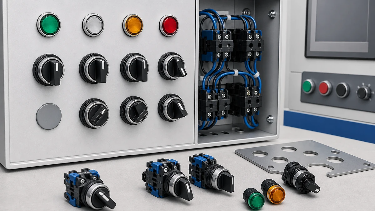
Selector switch applications span every layer of industrial machine control, from simple Hand-Off-Auto pump panels to multi-position motor reversing circuits and PLC-integrated operator interfaces. A selector switch holds its chosen position mechanically, routing control signals to a defined circuit path until the operator deliberately changes it. That sustained-position behavior distinguishes it from a pushbutton and makes it the correct component whenever a machine must lock into a specific operating mode. This article explains how selector switches are selected, wired, maintained, and documented for industrial control panels, with specific guidance on contact ratings, utilization categories, IP protection, and push button switch configuration.
How Selector Switches Work in Machine Control Panels
In an industrial control panel, a selector switch governs which circuit path is active at any given moment. A two-position unit commonly enables local versus remote control. A three-position unit handles Hand-Off-Auto configurations for motor starters, conveyor drives, and pump stations. Each handle position engages a specific set of contacts inside the switch body, directing 24 V DC signals to PLC discrete input modules or switching 120-240 V AC pilot circuits to relay or contactor coils.
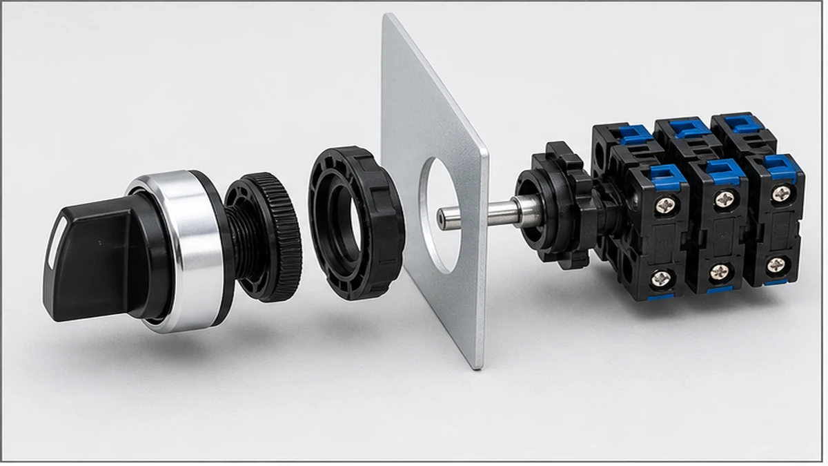
The contact switching action follows a cam-disc mechanism mounted on the actuator shaft. As the operator rotates the handle, machined cam lobes engage or release spring-loaded contact bridges at each indexed stop. A detent mechanism locks the shaft at each dwell angle, holding the cam in a stable position under panel vibration so that contact state does not drift between commanded positions.
For applications requiring more than four positions, or where multiple poles must switch in a defined sequence, push button selection reference provide configurable contact programs across multiple poles and a wide range of position counts, which is why they appear throughout machine tool, distribution, and motor control panel designs. Understanding selector switch reference and how its cam profile governs contact sequencing helps panel designers avoid incorrect contact-program selections during specification.
Selector Switch Application Types Across Machine Control
Hand-Off-Auto Control
HOA configurations represent one of the most common selector switch applications in pump stations, HVAC air-handling units, and conveyor motor starters. A three-position selector connects the load circuit to manual start control, a de-energized off state, or PLC-driven automatic sequencing. In typical panel wiring, the selector carries 24 V DC to the PLC input card or directly switches a 230 V AC coil circuit. Contact currents are generally low in signal-switching service, but the utilization category must still match the load type. A switch rated AC-12 for resistive loads will experience accelerated contact erosion if it is applied to inductive AC circuits, because the breaking energy is significantly higher than the rating was designed to handle.
Motor Reversing and Speed Selection
Multi-position selector switches appear in machine tool spindles, conveyor direction control, and fan speed staging. A four- or five-position cam switch routes power to different motor winding combinations or assigns run commands to individual contactors. These circuits carry higher switching currents than control signal circuits, and utilization category AC-23A applies when the contacts make and break directly under motor load conditions. The SH-B2 push button route series is frequently specified in this range due to its configurable multi-pole contact programs and panel-mount format, while the GQ metal push button route series addresses higher current ratings and more complex pole-stack requirements where panel depth and contact capacity allow.
Outdoor and Wash-Down Environments
In food processing lines, outdoor machinery, and marine control stations, selector switches are exposed to moisture, cleaning agents, and particulate contamination. IP65 or IP67 ingress protection per IEC 60529 is required in these locations. The IP rating must apply to both the front-panel seal and the internal contact housing independently. A switch that meets IP65 at the operator face but uses an unsealed contact block behind the panel door does not provide rated protection to the switching elements. Cable glands must also be correctly sized and torqued to maintain the enclosure IP class after wiring installation.
PLC and Safety Circuit Integration
Selector switches feeding PLC discrete input modules operate at 24 V DC sourced from a switched-mode power supply. Low-current signal circuits require stable contact resistance across the rated operating life, because a rising contact resistance in a 24 V DC loop with signal currents in the low milliamp range can introduce voltage drop errors sufficient to cause false input states. For safety-rated mode selection, such as enabling a maintenance bypass around a guard interlocking circuit, the switch may require positive-opening contact construction and a documented switching category per the applicable machinery safety standard. Confirm these requirements against the safety function assessment before selecting the switch model.
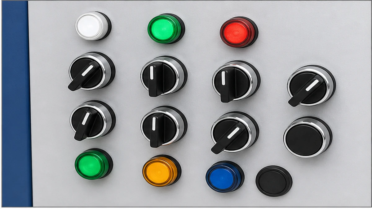
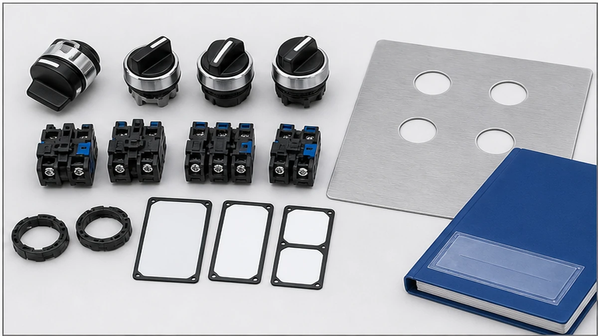
الشكل 2. يجب أن تراعي معايير الاختيار العوامل التالية: حجم المشغل، ونوع التوصيل، والجهد الكهربائي للمصباح، واللون، ومستوى الحماية IP، وفتحة اللوحة، والوثائق المرفقة.
Key Selection Criteria for Selector Switch Applications
Position Count and Circuit Architecture
Position count defines the number of discrete operating states required. Two-position selectors handle binary choices such as local versus remote. Three-position units cover HOA arrangements. Four- or five-position selectors appear in multi-speed or multi-mode machine tool applications. Each added position increases contact program complexity, so the cam disc configuration must be verified against the circuit’s required make-before-break or break-before-make sequence before ordering. In high-vibration installations, the detent mechanism must be confirmed against the machine’s measured vibration profile, because an undersized detent holding force allows the cam to drift off position without the operator’s input.
Contact Ratings and Utilization Category
Selector switch contacts must be rated for the load type they will make and break, not only the nominal steady-state current. the applicable control-device standard edition applies to switches, disconnectors, switch-disconnectors, and fuse-combination units for distribution and motor circuits, with rated voltage up to 1000 V AC or 1500 V DC. The standard establishes utilization categories that define required making and breaking capacity relative to load type. AC-22A applies to mixed inductive and resistive switching; AC-23A applies to motor loads. Sizing a switch to a resistive category and applying it to an inductive circuit is one of the most frequently observed causes of premature contact failure in industrial panels. Always confirm the rated insulation voltage Ui and rated operational current Ie from the manufacturer’s contact table for the specific utilization category, as these values vary by model and pole configuration. The control-device standard context provides the normative framework for these requirements, and the official IEC control-device publication is the authoritative reference for clause-level detail.
IP Protection and Environmental Classification
For panels in washdown, outdoor, or dusty production environments, confirm the required ingress protection class against IEC 60529 before finalizing the switch model. IP65 provides complete dust exclusion and protection against water jets from any direction. IP67 adds resistance to temporary immersion. The enclosure IP rating applies to the installed assembly with wiring and glands in place. A switch body rated IP65 can perform below that level if the panel cutout seal is distorted by incorrect bushing torque, if an incompatible gasket is used, or if cable gland selection does not match the entry diameter. These installation factors must be verified during panel commissioning, not assumed from the component specification alone.
Actuator Type and Operator Access Control
Actuator geometry affects ergonomics, panel density, and access control. Short-handle actuators suit high-density panels. Long-handle actuators improve grip in gloved operations. Key-lock actuators restrict mode changes to personnel who hold the correct key and are specified where unauthorized mode selection carries safety or process risk. Padlockable actuators support lockout/tagout (LOTO) procedures under applicable machinery safety requirements. A key-lock actuator restricts access but does not by itself constitute a complete LOTO program. Full lockout compliance requires documented isolation steps, verified de-energization, and physical lock application as separate procedural elements. The key-lock switch is one component within that broader process.
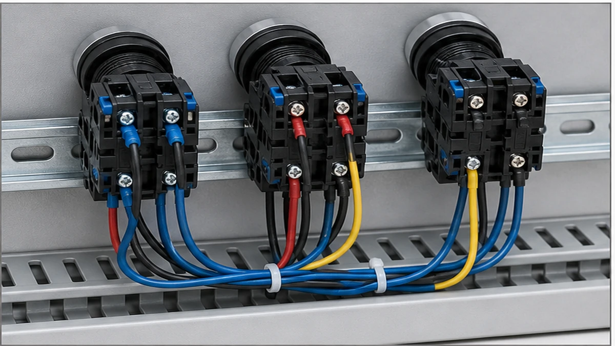
الشكل 3. يجب التحقق من سياق الأسلاك التطبيقية بالمقارنة مع مخطط التلامس الخاص بالشركة المصنعة قبل التنشيط.
Wiring and Installation Practices for Selector Switches
قائمة مراجعة ما قبل التركيب
Before mounting any selector switch, confirm the following against the panel drawing and switch datasheet:
Switch rating: Verify the rated insulation voltage Ui and utilization category match the circuit load type and voltage.
Panel cutout dimension: Confirm the cutout matches the switch body. A mismatched cutout creates mechanical stress on the bushing and degrades the IP seal.
Contact program: Cross-check the contact truth table against the logic diagram for every position. A selector switch with an incorrect contact program cannot be corrected after panel assembly without replacing the contact block.
Environmental rating: Confirm the enclosure IP class meets the installation zone requirement. IP65 is the practical minimum for washdown and outdoor locations.
Terminal torque values: Locate the terminal torque specification in the switch datasheet before wiring begins. Both under-torqued and over-torqued terminals cause contact reliability problems.
Wiring and Mounting Procedure
Step 1 – Mount the switch body: Insert the switch from the front of the panel door. Tighten the retention nut to the torque value stated in the product datasheet to achieve the rated IP seal without stressing the bushing. Do not apply a generalized torque value; retrieve the figure from the specific model’s documentation.
Step 2 – Terminate control conductors: Apply ferrules to all stranded conductors before insertion. Use the conductor cross-section specified in the datasheet for the circuit voltage and current. IEC 60204-1 provides minimum wiring requirements for machine control panels as a reference baseline, but always defer to the specific panel schematic and local wiring regulations.
Step 3 – Apply terminal torque: Tighten screw terminals to the datasheet value. Under-torqued terminals introduce intermittent resistance. Over-torqued terminals deform the terminal block and can crack insulation on smaller conductor sizes.
Step 4 – Label and route wiring: Assign wire numbers per the schematic and route control wiring in dedicated cable duct, separated from power conductors to minimize inductive interference on low-voltage signal circuits.
Step 5 – Functional verification: Before energizing, use a continuity tester to confirm each contact opens and closes at the correct switch position. Confirm no unintended continuity exists between positions or between positions and the ground bus. Document results in the panel test record.
For cam switch wiring in motor reversing and multi-speed applications, request the wiring diagram and cam profile chart from the switch manufacturer before beginning termination work. Contact sequencing errors in motor reversing circuits can create contactor simultaneous-closure conditions that trip protection devices or damage motor insulation.
How Shieldhz Confirms the Right Selector Switch Configuration for Your Application
Shieldhz is the export brand of Zhejiang Shihe Electric Co., Ltd., founded in 2014 and based in Yueqing, Wenzhou, Zhejiang Province. The company operates a manufacturing facility of more than 5,000 m2 with over 100 employees and 40 or more production machines, producing push button switches, push buttons, selector switches, and related control components to ISO 9001 quality management standards, with applicable products carrying CE, TUV, UL, UKCA, CCC, RoHS, and CB certification where relevant to the specific product family and export market.
When a buyer submits an inquiry for a selector switch application, Shieldhz requests the circuit diagram or contact truth table showing which poles must close or open at each rotary position. For a push button switch in a motor forward/reverse application, this typically means mapping three- to four-pole contact arrangements across three to five positions, with each position’s make/break sequence verified against the utilization category. The engineering team confirms whether AC-22A or AC-23A applies based on the load description and switching conditions provided.
Shieldhz confirms the actuator style alongside the panel cutout dimension and mounting depth. Many industrial enclosures constrain available mounting depth, which determines whether a standard or short-body frame is required. Key-operated versions require confirmation of the key-retain or key-release preference at each position, because this affects the physical key management procedure the panel operator must follow.
For the contact program itself, the Shieldhz team cross-references the requested position count, pole count, and NO/NC combination against the available cam disc profiles in the product family. Where a standard contact program matches the application, the model reference is confirmed directly. Where a non-standard program is needed, the engineering team advises whether a modified cam stack can be assembled within the standard frame or whether a different series is more appropriate.
For outdoor or washdown environments, the required ingress protection class is validated against the installation condition and the available gasket and sealing options for the specified model. Documentation prepared before order confirmation includes the contact truth table, dimensional drawing, wiring diagram, and applicable certification documents relevant to the buyer’s market. Buyers can submit circuit requirements, operating voltage, pole count, position count, and enclosure IP class through the Shieldhz product inquiry process to receive a configured model recommendation with full technical documentation.
الشكل 4. يجب أن يتضمن الاستفسار الكامل التصنيف وتسلسل التلامس والتركيب والحاوية ومتطلبات المستند.
Selector Switch Maintenance and Service Life in Industrial Panel Environments
Selector switch service life in machine control environments depends on rated mechanical operating cycles, contact material grade, and the severity of the electrical load being switched. Mechanical endurance and electrical endurance are not the same figure. Mechanical endurance is measured under no-load conditions and is always higher than electrical endurance under rated current and inductive load. Always retrieve both figures from the product datasheet for the specific utilization category, because published endurance values vary significantly between switch series and contact configurations.
Common Failure Modes in Field Conditions
The most frequently observed failure modes in industrial panel selector switches follow a predictable progression:
Contact pitting and erosion from repetitive arc discharge under inductive AC loads increases contact resistance gradually until intermittent signal loss occurs. This failure mode develops silently before any visible damage appears on the contact surface.
Detent mechanism wear causes the cam or ball-and-spring assembly to lose positioning accuracy, resulting in incomplete contact engagement at intermediate positions. The first detectable sign is a reduction in the tactile resistance felt during handle rotation.
Seal degradation on IP-rated panel-mount switches exposed to cleaning solvents or machine fluid aerosols allows contamination to migrate onto contact surfaces, accelerating corrosion and increasing contact resistance in service environments that would not otherwise cause electrical wear.
Actuator shaft loosening from sustained panel vibration leads to positional drift without mechanical failure of the contacts themselves. In high-vibration machinery, this failure mode can precede contact wear as the primary cause of control circuit faults.
Maintenance Protocol
Maintenance intervals should be based on operating cycle count rather than elapsed calendar time. A practical framework is:
At 100,000 cycles or 12 months, whichever comes first: Visual inspection for contact discoloration, detent feel verification, and enclosure seal integrity check.
At 300,000 cycles: Contact resistance measurement with a milliohmmeter at each switch position. Rising resistance values indicate approaching end-of-life before visible erosion is present.
At or before the rated electrical endurance limit: Full contact block replacement regardless of visual condition. Do not defer replacement because the contacts appear intact. Electrical endurance limits are established under controlled test conditions and represent a reliability boundary, not a visible wear threshold.
When troubleshooting intermittent control faults, correlate the fault event log with the machine’s cycle counter before replacing switch hardware. Electrical endurance limits are frequently reached before physical damage is visible, and a switch that appears serviceable may already be operating beyond its rated switching capacity for the specific utilization category applied in that circuit.
Replacement contact block specifications must be confirmed against the original datasheet for contact material grade, rated insulation voltage Ui, and utilization category. Installing a replacement contact block from a different series or with a different utilization category rating changes the protection coordination assumptions that were established during the original panel design.
الأسئلة الشائعة
What is the difference between a selector switch and a pushbutton in a machine control panel?
A selector switch holds its actuated position mechanically until the operator deliberately moves it to another position, making it suitable for mode selection tasks such as Hand-Off-Auto where the chosen state must persist between operator interactions. A pushbutton returns to its resting state when released, so it is used for momentary commands such as start and stop rather than sustained mode assignments. Using a pushbutton where a selector is required means the machine loses its mode state whenever an operator or maintenance technician touches the panel, which creates control reliability problems in automated sequences.
How do I determine the correct utilization category for a selector switch in my application?
Identify the load type that the switch contacts will make and break under the worst-case switching condition. Inductive AC loads such as contactor coils or solenoid valves require AC-15 for pilot duty circuits or AC-23A for direct motor switching. DC electromagnet loads fall under DC-13. Mixed inductive and resistive loads use AC-22A. Sizing to a resistive category such as AC-12 and applying the switch to an inductive circuit accelerates contact erosion because the switch was not designed for the higher breaking energy associated with inductive load interruption. Confirm the specific rated operational current Ie for the chosen utilization category from the manufacturer’s contact table, as the same switch model may carry different current ratings across different utilization categories.
Can a 22 mm selector switch and a 30 mm selector switch be used interchangeably?
No. The panel cutout diameter, mounting collar thread, contact block dimensions, and available pole count differ between 22 mm and 30 mm body sizes. Substituting one for the other requires a different panel cutout, which typically means replacing the panel door or subplate. The choice between body sizes is driven by contact current requirements, available panel space, operator ergonomic preferences, and the specific contact programs available in each series rather than by interchangeability between them.
What causes a selector switch to feel loose or fail to hold its position?
Positional drift and a loose feel during handle rotation most commonly result from detent mechanism wear. The ball-and-spring or roller-and-notch assembly inside the cam body loses its holding force as the contact surfaces wear over operating cycles, and the switch no longer indexes firmly at each position. In high-vibration installations, this wear accelerates because the vibration continuously loads the detent against its spring. Specifying a switch series with a roller-type detent and confirming the vibration resistance rating against the machine’s measured vibration profile prevents this failure mode in service. Do not attempt to adjust detent spring force in the field without confirming the procedure with the switch manufacturer, as this affects both positioning accuracy and contact engagement geometry.
How often should selector switches be inspected or replaced in a continuous-production environment?
Inspection intervals should be based on operating cycle count rather than elapsed time, because a selector switch on a high-frequency production line may accumulate 100,000 cycles in a few months while an identical switch on a low-frequency application may take several years to reach the same count. A practical baseline is a visual and tactile inspection at 100,000 cycles or 12 months, whichever comes first, with contact resistance measurement at 300,000 cycles. Contact block replacement should be planned at or before the manufacturer’s stated electrical endurance limit for the specific utilization category, regardless of whether visible wear is present at that point.
What IP rating is required for a selector switch installed in a food processing facility?
Most food processing environments require a minimum of IP65, which provides complete dust exclusion and protection against water jets from any direction per IEC 60529. Areas subject to high-pressure chemical washdown cycles may require IP67 or higher, depending on the jet pressure, dwell time, and cleaning agents used. The IP rating must apply to both the front panel seal and the internal contact housing independently, and must be confirmed with the wiring and cable glands installed and torqued to specification. A component-level IP rating from the switch datasheet does not automatically transfer to the installed assembly if gland selection or bushing torque is incorrect.
Does a key-lock selector switch satisfy lockout/tagout requirements on its own?
A key-lock actuator provides a meaningful physical barrier against unauthorized mode changes and supports the intent of lockout/tagout procedures, but it does not constitute a complete LOTO program under ISO 14118 or equivalent machinery safety isolation requirements. Full LOTO compliance requires documented energy isolation steps, physical application of a personal safety lock, verified de-energization, and confirmation that all stored energy has been dissipated before work begins. The key-lock selector switch is one element within that broader procedural framework. Its role and limitations should be defined in the machine’s energy control procedure document rather than assumed from the component specification.
شي، موكسي
يكتب شي، موكسي مقالات شيلدهز الفنية لمشتري التحكم الصناعي والمكونات الكهربائية، والتي تغطي مفاتيح الكامات الدوارة، ومفاتيح العازل، ومفاتيح فصل التيار المستمر الكهروضوئية، وأزرار الضغط، وأضواء المؤشر، والحاويات المقاومة للماء، والكتل الطرفية. تستند المقالات على خبرة شركة Zhejiang Shihe Electric Co., Ltd. في التصنيع والتصدير، مع التركيز العملي على اختيار الطراز وأوراق البيانات والرسومات والشهادات وتصنيفات IP وتفاصيل الاستفسار التي يجب على المشترين التأكد منها قبل الطلب.