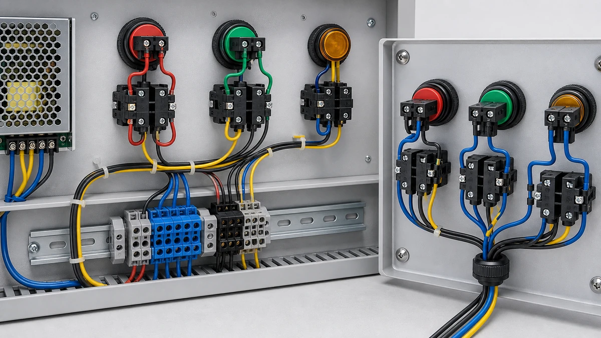
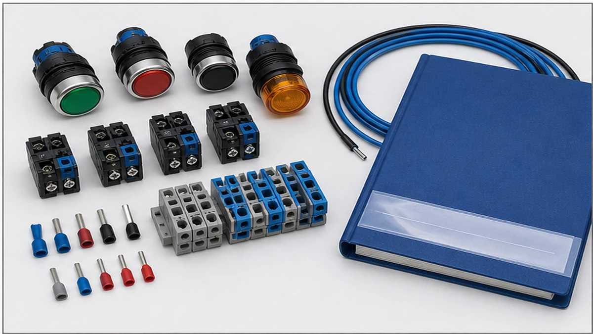
Push button wiring basics cover how momentary-contact push buttons, contactors, and indicator lights connect into control circuits that start, stop, and signal the operating state of industrial loads. In a correctly built start-stop station, a normally open Start button energizes the contactor coil, a normally closed Stop button interrupts it, and a seal-in auxiliary contact holds the coil energized after the Start button is released. Indicator lamps wired across the coil or auxiliary contacts give operators a continuous visual status. Getting contact type, terminal numbering, and wiring sequence right before first power-on prevents the most common commissioning faults seen in industrial control panels.
حدود الأمان: This wiring section is not a DIY instruction. Push button wiring, testing, commissioning, and troubleshooting should be handled by qualified electrical personnel under the site lockout/tagout procedure. Before opening a panel or checking terminals, de-energize the relevant circuit where the procedure requires it and verify absence of voltage with suitable test equipment.
What Push Button Wiring Involves: Core Concepts
Push button control circuits operate at a control voltage that is separate from the load voltage. In most modern panels that control means 24 V DC from a dedicated power supply, although 110 V AC and 230 V AC control transformers remain common in older or regionally standardized installations. The load side may carry 230 V AC single-phase or 400 V AC three-phase at whatever current the motor or load requires. Understanding this separation is the first step: push button contacts switch the control coil, not the main load.
Normally Open and Normally Closed Contacts
A normally open (NO) contact has no electrical path between its terminals at rest. Pressing the actuator bridges the contacts and completes the circuit. A normally closed (NC) contact maintains a continuous path at rest and opens only when the actuator is pressed. the applicable control-device standard governs low-voltage control circuit devices including push buttons, contact ratings, utilization categories, and endurance requirements. Under that standard, the Stop function must use an NC contact wired in series with the control coil path so that any wire break, contact failure, or actuator fault defaults to de-energizing the load — the safe state.
The Latching Circuit
A momentary push button cannot hold a motor running on its own because the contact returns to its resting state the instant the operator releases the button. The solution is a latching or seal-in circuit: an NO auxiliary contact on the contactor is wired in parallel with the Start push button. When the Start button is pressed and the contactor coil energizes, the auxiliary contact closes and takes over the task of maintaining coil current. The operator can release the Start button and the coil remains energized through the auxiliary path. Pressing the Stop button breaks the NC contact, interrupting the entire control loop, dropping the coil, and opening both the main and auxiliary contacts simultaneously.
This self-holding architecture is fundamental to safe machine control because it also fails safe on supply interruption: if control power is lost the coil drops and the machine stops, requiring a deliberate restart rather than an automatic one.
Indicator Light Integration
Pilot lamps translate contactor state into visible information at the control station. A green RUN lamp wired in parallel with the contactor coil illuminates whenever the coil is energized. A red STOP lamp wired through an NC auxiliary contact on the contactor stays lit at rest and extinguishes when the contactor pulls in. This pairing gives operators positive confirmation of actual contactor state rather than simply indicating that control power is present.
Wiring a Start-Stop Circuit: Step-by-Step Sequence
Tracing exactly how each wire connects — before a single conductor is terminated — prevents sequencing errors that cause unintended starts, failed stops, or broken seal-in conditions.
Circuit Components and Their Roles
A standard start-stop circuit contains four core elements:
An NC Stop push button in series with the control coil path
An NO Start push button also in series with the coil path, after the Stop contact
A contactor coil rated at the panel control voltage
One NO auxiliary contact on the contactor, wired in parallel with the Start button to form the seal-in path
An indicator lamp or lamps can be added to the circuit without altering the logic.
Numbered Wiring Sequence
Connect the control supply line (L1 phase, 24 V DC positive, or control transformer secondary hot terminal) to terminal A of the Stop button NC contact.
Wire terminal B of the Stop button to terminal C of the Start button NO contact.
Wire terminal D of the Start button to contactor coil input terminal A1 and simultaneously to one terminal of the auxiliary NO contact.
Return the second terminal of the auxiliary NO contact to terminal C — the junction between the Stop and Start buttons — creating the seal-in parallel path.
Connect contactor coil terminal A2 to the control supply neutral or DC negative to complete the coil circuit.
Wire the green indicator lamp across A1 and A2 if run-status feedback is required.
Circuit Logic in Operation
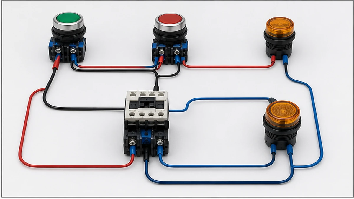
Pressing the Start button momentarily routes current through the NC Stop contact, through the NO Start contact, and into the contactor coil, energizing it. The contactor closes its main power contacts and simultaneously closes the auxiliary NO contact. Current now flows through the NC Stop contact and the auxiliary contact directly to the coil, bypassing the Start button entirely. Releasing the Start button has no effect. Pressing the Stop button opens the NC contact, the full control loop loses continuity, the coil drops, and main and auxiliary contacts both open.
If the motor runs only while the Start button is held, the seal-in auxiliary contact is either absent from the wiring or connected in series with the Start button rather than in parallel. Check the junction point between Stop and Start terminal B/C first.
If pressing the Stop button has no effect, the Stop button contact block may be wired as NO instead of NC — a contact wired in the wrong type passes continuity when closed (at rest) and the circuit simply re-closes through it even when the button is pressed.
Before applying control voltage for the first time, use a continuity tester with the contactor manually held in by hand to confirm the seal-in path: the auxiliary NO contact should close between the junction point and coil terminal A1, and releasing the manual hold should open that path.
Contact Types and Terminal Identification
Recognizing contact type on the bench before a single wire is cut is the single most time-efficient commissioning practice for start-stop panels.
IEC Terminal Numbering Scheme
the applicable control-device standard assigns standardized terminal numbers to contact blocks on control circuit devices. This scheme allows wiring teams to trace circuits from schematic to physical installation without physically chasing conductors through conduit.
Contact Type
Resting State
IEC Terminal Numbers
NO, first block
مفتوح
13 – 14
NC, first block
مغلق
21 – 22
NO, second block
مفتوح
33 – 34
NC, second block
مغلق
41 – 42
The line-side terminal always carries the lower number; the load-side terminal the higher number. A push button body fitted with one NO block and one NC block will show terminals 13, 14, 21, and 22. Additional contact blocks follow the sequential pattern: 33/34 for a second NO, 41/42 for a second NC.
Current and Utilization Category
Contact current ratings and utilization categories are defined in the applicable control-device standard. AC12 applies to resistive and solid-state loads; AC15 applies to inductive AC loads such as contactor coils. For low-level PLC input circuits, confirm that the selected contact block is specified for operation at signal-level currents, sometimes as low as 5 mA, to prevent dry-circuit failure. Always confirm the specific ratings from the product datasheet rather than assuming a universal value, as contact material and frame size both affect the published figures.
The SH-B2 push button switch follows this IEC terminal numbering scheme, and contact blocks can be added or swapped in the field while maintaining full schematic traceability. Before ordering, confirm the number of NO and NC poles, the rated insulation voltage Ui, and the utilization category against the circuit diagram.
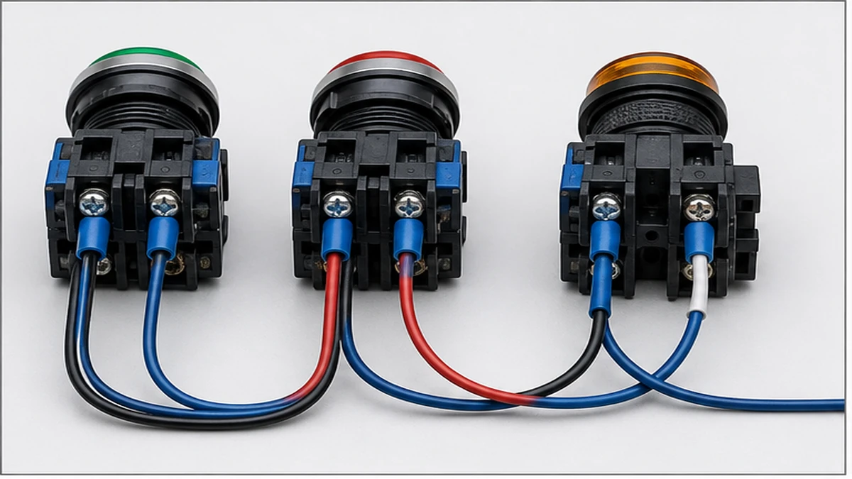
الشكل 2. يجب أن تراعي معايير الاختيار العوامل التالية: حجم المشغل، ونوع التوصيل، والجهد الكهربائي للمصباح، واللون، ومستوى الحماية IP، وفتحة اللوحة، والوثائق المرفقة.
Indicator Light Wiring: Pilot Lamps in Start-Stop Circuits
Indicator lights are not decorative. Their placement in the circuit determines whether they confirm actual machine state or simply report control power presence — a meaningful distinction during fault diagnosis.
Wiring Configurations and Use Cases
التكوين
Connection Point
Lamp State Running
Lamp State Stopped
الاستخدام النموذجي
Coil-parallel
Across A1-A2 coil terminals
ON
إيقاف التشغيل
Green RUN indicator
NC auxiliary contact
Through NC contact on contactor
إيقاف التشغيل
ON
Red STOP indicator
NO auxiliary contact
Through NO contact on contactor
ON
إيقاف التشغيل
Secondary RUN confirmation
Overload relay NC
Through overload relay NC contact
إيقاف التشغيل
ON on fault
Amber FAULT indicator
Supply-parallel
Directly across control supply
ON whenever powered
OFF on supply loss
Panel energized indicator
A three-lamp arrangement — green for RUN, red for STOP, amber for FAULT — is widely used in motor control panels because it allows operators to distinguish a normal stop from a tripped overload without opening the enclosure. Wire the red STOP lamp through the NC auxiliary contact on the contactor rather than directly across the supply; this confirms that the contactor has actually dropped out, not merely that the Start button was pressed.
Pilot lamps are typically rated for 24 V DC, 110 V AC, or 230 V AC. Confirm the lamp supply voltage against the actual control circuit voltage before installation. A voltage mismatch of even 10 V to 15 V above the LED driver rating can shorten service life significantly or cause continuous dim illumination at rest.
the applicable control-device standard treats the lamp circuit as a separate control branch. Each lamp connection should be considered for its own overcurrent protection rather than simply tapped from an adjacent control conductor without evaluation.
When a green RUN lamp stays dimly lit after stopping, the most likely cause is a leakage path through an adjacent wiring run or a failing LED driver. Isolate the lamp branch and retest before replacing the module. For panels in dusty environments, schedule LED lens cleaning at the same interval as contactor contact inspections because accumulated dust reduces readability before the lamp itself fails.
الشكل 3. يجب التحقق من سياق الأسلاك التطبيقية بالمقارنة مع مخطط التلامس الخاص بالشركة المصنعة قبل التنشيط.
Common Wiring Mistakes and How to Avoid Them
The faults listed below account for the majority of first-power-on failures in start-stop panels. Each can be caught before control voltage is applied if the verification sequence is followed.
Contact Type Errors
Wiring a Stop button to a NO contact instead of an NC contact is the most frequent error. The circuit will pass a dead-circuit continuity check because the NC rest state presents a closed path — but the fault becomes visible only under power when pressing Stop has no effect. Verify every contact block label against the schematic before terminating any wire.
Similarly, wiring the Start button to an NC contact rather than NO means the motor will run continuously when control power is applied and will stop only when the Start button is pressed. This is the reverse of the intended behavior and a safety hazard.
Seal-In Path Errors
If the auxiliary NO contact is connected in series with the Start button rather than in parallel, the motor runs only while the Start button is held. If the auxiliary contact is wired to the wrong junction point — for example, between the Stop button and the supply rail rather than between the Stop and Start buttons — the seal-in path bypasses the Stop button, making it impossible to stop the motor from the control station.
Terminal Torque and Connection Quality
All terminal screws should be tightened to the torque value stated in the component datasheet. Control circuit terminal torques vary by terminal frame size; using the published value prevents both loose connections that cause intermittent faults and overtightened connections that crack insulation or strip threads. Do not assume a universal value.
Voltage Rating Mismatches
Connecting a 24 V DC lamp to a 230 V AC supply, or a 230 V AC coil to a 24 V DC supply, causes immediate failure or no operation. Confirm supply voltage at the actual terminals using a calibrated meter before energizing components. Labeling the control supply voltage on the panel door and at the terminal rail eliminates this error during future service visits.
Grounding and IP Rating
Verify that the panel earth stud connects to each push button enclosure and that the earth conductor is within the terminal block area. For wet, washdown, or outdoor environments, use push buttons rated at a minimum of IP65 per IEC 60529, which confirms complete dust exclusion and protection against water jets. Environments involving temporary immersion or high-pressure spray may require IP67 or IP69K; confirm the site requirement before specifying the product.
Documentation Errors
Unlabeled terminals and missing as-built diagrams are the most persistent maintenance hazards in panel wiring. Before commissioning sign-off, confirm every terminal is tagged with its wire number and that the physical installation matches the schematic exactly. This step reduces fault diagnosis time during every future service call on the panel.
How Shieldhz Confirms Push Button Configuration Before Shipment
Shieldhz is the export brand of Zhejiang Shihe Electric Co., Ltd., founded in 2014 and based in Yueqing, Zhejiang. The company operates a factory of more than 5,000 m2 with over 100 employees and 40-plus production machines. Certifications held include ISO 9001, CE, RoHS, TUV, UL, UKCA, CCC, and CB. The pre-shipment verification process described here is designed to intercept the same wiring and configuration errors covered in the previous section before components reach the panel builder.
Contact Block Configuration Review
When a buyer submits an inquiry for a product such as the SH-B2 push button switch, the Shieldhz engineering team reviews the requested NO and NC contact arrangement, the operating voltage, and the rated current against any circuit diagram provided. If a contact type mismatch is identified — for example, an NC contact specified in a position where the wiring diagram shows an NO block — the configuration is flagged and queried before production is confirmed. Buyers are also asked to confirm the number of contact poles and whether an illuminated actuator with an integrated LED is required, including the LED supply voltage and color code.
Utilization Category and Rating Verification
The rated insulation voltage Ui, rated impulse withstand voltage Uimp, and the applicable utilization category (AC12, AC15, or DC13 for DC coil circuits) are checked against the declared circuit conditions. If the stated application involves PLC digital input cards operating at signal-level currents, the team confirms that the specified contact block is rated for low-current operation at those levels. Product ratings are taken from the current datasheet rather than from assumed universal values.
Wiring Diagram and Documentation Release
Once the contact program is confirmed, Shieldhz provides a wiring diagram aligned to the applicable control-device standard. The diagram shows terminal numbers in the IEC standard scheme, contact resting state, and LED polarity for illuminated models. For indicator lamp circuits, the lamp voltage is cross-checked against the declared control supply voltage. The outgoing documentation package includes the confirmed wiring diagram, product datasheet, dimensional drawing, and applicable test certificates. Buyers requiring CE, CCC, or TUV documentation should state this at the inquiry stage so the correct certificate version is prepared before goods are dispatched.
Enclosure and IP Requirement Confirmation
The enclosure mounting environment and the required IP ingress protection rating are confirmed as part of the model selection process. Panel-front sealing is specified per IEC 60529; if the declared environment requires IP65 or above, the correct actuator seal ring and nut torque specification are included in the shipment documentation.
To discuss contact configuration for your control circuit, provide your circuit diagram, operating voltage, enclosure IP requirement, and any certification documentation needs at the inquiry stage for a precise model confirmation.
Selecting the Right Push Button: Specifications That Matter
Matching specifications to circuit conditions at the start of the design process — rather than after panel assembly — eliminates the late-stage rework that contact mismatches and rating mismatches cause.
Rated Voltage and Insulation Voltage
The push button’s rated insulation voltage Ui must meet or exceed the circuit’s maximum operating voltage. Control circuits typically operate at 24 V DC, 110 V AC, or 230 V AC. Operating a device below its rated insulation voltage is safe; operating above it risks insulation breakdown over time. Always confirm Ui from the product datasheet, not from a general-purpose assumption.
Contact Current Rating and Utilization Category
Control circuit push buttons carry contact current ratings that vary by frame, contact material, and utilization category. AC15 (inductive AC load, contactor coil circuits) and DC13 (inductive DC load, PLC and relay coil circuits) produce greater contact stress than AC12 or DC12 (resistive loads). Selecting a device rated at the correct utilization category for the actual load type — rather than the highest resistive rating — ensures the contact block endurance stated in the datasheet applies to the installation.
For PLC input circuits at signal-level currents, confirm that the contact block specification explicitly covers operation at those current levels to avoid dry-circuit failure.
IP Ingress Protection
Clean indoor control rooms may accept IP40 or IP54. Industrial production floors with cutting fluid or coolant spray typically require IP65 as a minimum. Wash-down environments in food processing or pharmaceutical production may specify IP67 or IP69K. Confirm the site classification against IEC 60529 before specifying product.
تكوين جهة الاتصال
State explicitly whether the circuit requires NO, NC, or a combined NO-plus-NC arrangement. Confirm the total number of contact poles needed. For circuits that require position feedback to a PLC as well as coil control, a two-contact-block arrangement with separate NO and NC blocks on the same actuator is standard.
Actuator Type
Select the actuator based on the operator interface requirement. Momentary flush buttons suit standard start and stop functions. Extended mushroom-head actuators provide a larger target surface for emergency or high-frequency use. Illuminated actuators integrate a pilot lamp into the button body, reducing panel cutout count and wiring connections. Key-switch actuators restrict operation to authorized personnel. Each actuator type accepts the same contact block format in 22 mm mounting diameter products, allowing changes in the field without re-drilling the panel.
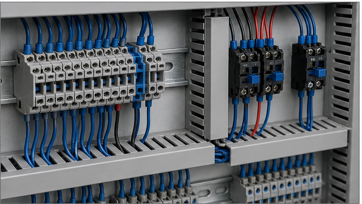
الشكل 4. يجب أن يتضمن الاستفسار الكامل التصنيف وتسلسل التلامس والتركيب والحاوية ومتطلبات المستند.
For control panels that also include mode-selection or source-changeover functions, the push button selection reference provides maintained multi-position switching to complement the momentary push button circuits described in this guide. The SH-B2 push button route and GQ metal push button route are commonly specified alongside push button stations in motor control centers and distribution panels where a maintained selector position is required for mode control. For panels where switch-disconnector or fuse-combination unit functions are also present, selector switch reference applies to switches, disconnectors, switch-disconnectors, and fuse-combination units for distribution and motor circuits, with rated voltage up to 1000 V AC or 1500 V DC. The full standard text is maintained by the IEC and available through the official IEC control-device publication.
الأسئلة الشائعة
ما الفرق بين ملامس زر الضغط «المفتوح عادةً» و«المغلق عادةً»؟
A normally open contact has no electrical path between its terminals until the button is pressed; pressing the actuator bridges the contacts and completes the circuit. A normally closed contact maintains a continuous path at rest and opens only when the actuator is pressed. Start buttons use NO contacts. Stop and safety buttons use NC contacts so that a wire break, contact failure, or missing actuator defaults to the safe de-energized state. the applicable control-device standard defines terminal numbers 13/14 for NO contacts and 21/22 for NC contacts, allowing identification from the schematic without physically tracing the installed wire.
Why does my motor stop the moment I release the Start button?
This almost always means the seal-in auxiliary contact on the contactor is either absent from the wiring or connected in series with the Start button rather than in parallel. The NO auxiliary contact must bridge the same two terminals as the Start button — the junction between the Stop and Start buttons, and the coil terminal — so that it takes over the coil-holding function once the button is released. Use a continuity tester with the contactor manually held in to verify the seal-in path before applying control voltage.
What control voltage do start-stop circuits typically use?
The most common control voltages are 24 V DC in PLC-integrated panels and 110 V AC or 230 V AC in traditional hardwired motor control circuits. The control voltage is determined by the panel control transformer secondary or DC power supply and must match the rated coil voltage of the contactor and the supply voltage rating of any pilot lamps in the circuit. Confirm the actual supply voltage at the terminal with a calibrated meter before energizing components.
How do I wire a green RUN light and a red STOP light correctly?
Wire the green lamp in parallel with the contactor coil — across terminals A1 and A2 — so it illuminates only when the coil is energized. Wire the red lamp through a normally closed auxiliary contact on the contactor so it stays lit when the machine is at rest and extinguishes when the contactor pulls in. This arrangement confirms actual contactor state rather than simply indicating that control power is present. Connecting both lamps directly across the supply gives no information about whether the contactor has actually operated.
What IEC standard governs push button contact ratings?
the applicable control-device standard covers low-voltage control circuit devices including push buttons, selector switches, and indicator lights. It defines contact ratings, utilization categories (AC12, AC15, DC12, DC13), endurance requirements, and the terminal numbering scheme used to identify contact type on compliant devices. When evaluating a push button datasheet, confirm that the published current rating is stated for the utilization category that matches the actual load type in your circuit.
What IP rating do I need for an outdoor or washdown push button installation?
A minimum of IP65 per IEC 60529 is required for outdoor or general washdown environments. IP65 confirms complete dust exclusion and protection against water jets from any direction. Environments with heavier spray, temporary immersion, or high-pressure cleaning require IP67 or IP69K respectively. Confirm the site classification — particularly in food processing, marine, or chemical environments — before specifying product, as an undersized IP rating will allow ingress that degrades contacts and LED lamp modules over time.
Can I use an illuminated push button to combine the command and status indicator functions?
Yes. Illuminated push button actuators integrate a momentary contact block with an LED pilot lamp module in a single 22 mm body. The contact block operates the control circuit in the normal way while the lamp module is wired to confirm circuit state — for example, a Start button with a green LED that illuminates when the contactor coil is energized. This reduces panel cutout count and total wiring connections, and it is standard practice in compact control stations where a separate dedicated indicator position is not practical. Confirm that the LED module voltage matches the control supply voltage before installation.
شي، موكسي
يكتب شي، موكسي مقالات شيلدهز الفنية لمشتري التحكم الصناعي والمكونات الكهربائية، والتي تغطي مفاتيح الكامات الدوارة، ومفاتيح العازل، ومفاتيح فصل التيار المستمر الكهروضوئية، وأزرار الضغط، وأضواء المؤشر، والحاويات المقاومة للماء، والكتل الطرفية. تستند المقالات على خبرة شركة Zhejiang Shihe Electric Co., Ltd. في التصنيع والتصدير، مع التركيز العملي على اختيار الطراز وأوراق البيانات والرسومات والشهادات وتصنيفات IP وتفاصيل الاستفسار التي يجب على المشترين التأكد منها قبل الطلب.