Endereço
304 North Cardinal St.
Dorchester Center, MA 02124
Horas de trabalho
De segunda a sexta-feira: das 7h às 19h
Fim de semana: 10:00 - 17:00
Endereço
304 North Cardinal St.
Dorchester Center, MA 02124
Horas de trabalho
De segunda a sexta-feira: das 7h às 19h
Fim de semana: 10:00 - 17:00
Obtenha chaves rotativas, isoladores e componentes de painel de primeira qualidade diretamente do fabricante.
Preencha o formulário abaixo para obter preços, catálogos e suporte técnico.
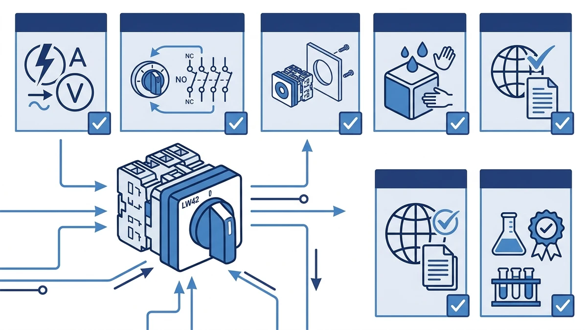
Aprenda os conceitos básicos do interruptor de came rotativo LW42, verificações de seleção, contexto de fiação, notas da IEC 60947-3 e orientação ao comprador da Shieldhz.
The LW42 rotary cam switch is a multi-position selector switch built for compact industrial panel installations. It uses a rotating cam disc mechanism to open and close discrete contact circuits at defined angular positions, typically in 45 or 90 degree steps, with compact Shieldhz LW42 variants commonly positioned around 20A, 25A, and 32A changeover applications; exact insulation voltage, AC-23A/AC-3 data, and mounting options must be confirmed from the current datasheet. For panel builders and control engineers, the LW42 answers a specific need: reliable multi-circuit switching within a small panel footprint, without the component count that separate relays or contactors would require. This article covers how the switch works, how to wire it, how it compares to adjacent series, and what to verify before ordering.
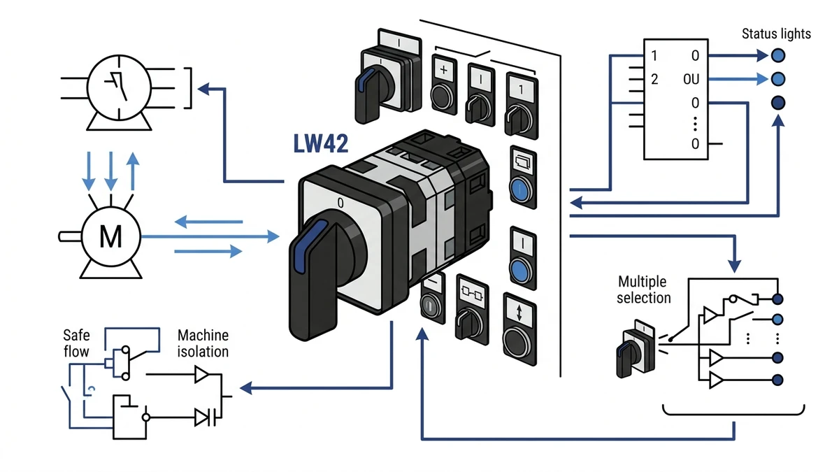
The LW42 is a compact rotary cam switch designed for front-panel mounting in industrial control enclosures. When the operator turns the actuator knob, a precision-machined cam disc rotates against a stack of stationary contact carriers. Each angular step engages or disengages specific silver-alloy contact bridges, directing current through pre-defined circuit paths.
This cam-to-contact relationship is what separates a rotary cam switch from a simple on/off toggle. A single shaft rotation can manage multiple independent circuits simultaneously, which is why the LW42 appears in motor direction control, source changeover, and metering selector applications where one operator action must control several circuit paths at once.
For a broader introduction to how cam switches work across different series and current ratings, the rotary cam switch overview covers the full product family context.
The LW42 consists of five main assemblies:
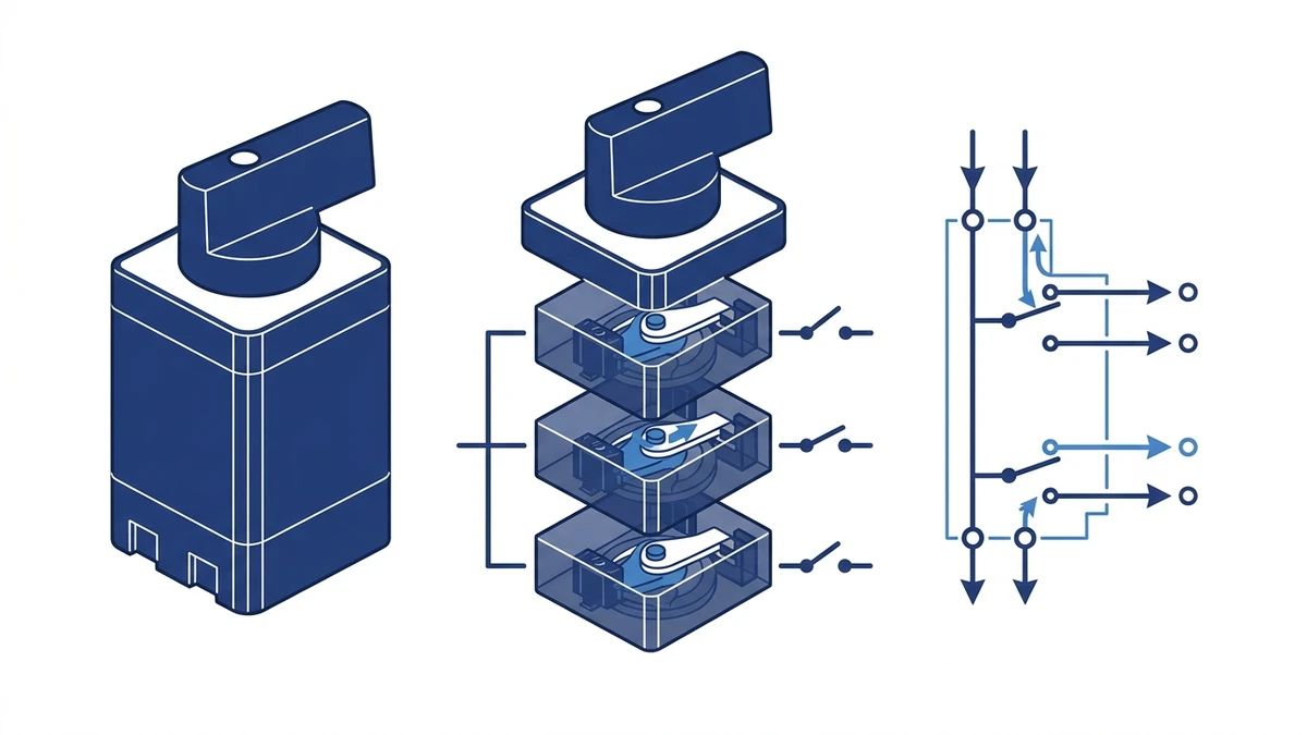
Each cam disc is profiled to a specific switching program. As the actuator shaft turns through discrete angular positions, each cam lobe either lifts or releases a spring-loaded contact bridge, opening or closing specific circuit poles in a defined sequence.
When a lobe engages the contact carrier follower, it compresses the contact spring and separates the silver-alloy contact bridge from its stationary counterpart, breaking the circuit. When the lobe clears, the spring drives the bridge back into contact, completing the circuit. In a properly maintained cam switch, contact resistance should stay close to the commissioning baseline; exact acceptable values are datasheet- and test-method-dependent. The exact spring preload and contact resistance values for a specific LW42 variant should be confirmed from the product datasheet, as they vary by pole configuration and contact material grade.
The contact material in the LW42 is a silver-based alloy, chosen for low contact resistance and resistance to welding under inductive load switching. IEC 60947-3:2020+AMD1:2025 applies to switches, disconnectors, switch-disconnectors, and fuse-combination units for distribution and motor circuits, with rated voltage up to 1000V AC or 1500V DC. It defines the making and breaking capacity requirements that cam switch contacts must satisfy across their rated utilization categories, including AC-21A for resistive loads and AC-23A for motor loads. The full standard is available from the IEC webstore.
The table below shows a representative four-position switching program, illustrating which poles are closed or open at each detent position. The symbol (C) indicates closed and (O) indicates open.
| Position | Pole 1 | Pole 2 | Pole 3 | Pole 4 |
|---|---|---|---|---|
| 0 (Off) | O | O | O | O |
| 1 | C | O | C | O |
| 2 | C | C | O | O |
| 3 | O | C | C | C |
Actual contact programs vary by switching configuration. The LW42 rotary cam switch series supports multiple cam disc arrangements to match specific motor control, changeover, and isolation sequences. Always verify the cam disc switching diagram against your actual circuit before wiring. The printed position diagram on the housing reflects the factory-default program, which may not match a custom-ordered configuration.
In a typical motor control panel, the cam switch position sequence maps directly to star-delta starting or forward-reverse logic, with each detent providing a stable, vibration-resistant contact state that a simple toggle or push button cannot replicate.
Four checks that experienced panel builders perform at commissioning:
For the LW42, do not copy ratings across variants: current Shieldhz information positions LW42 around compact 20A, 25A, and 32A changeover uses, while Ui, Uimp, Ith, endurance, and dimensions remain part-number-specific datasheet fields. Contact material and endurance should be confirmed from the current Shieldhz datasheet. Exact endurance cycle counts and dimensional tolerances should be confirmed from the current Shieldhz datasheet, as these values are subject to revision between product generations.
| Parâmetro | Typical Value |
|---|---|
| Rated Voltage (AC) | Up to 380V AC |
| Tensão nominal de isolamento (Ui) | 500V AC |
| Rated Impulse Withstand (Uimp) | 6 kV |
| Corrente térmica (Ith) | 20A |
| Utilization Category | AC-23A (IEC 60947-3) |
| Available Poles | 1P, 2P, 3P, 4P |
| Switching Positions | 2, 3, or 4 positions |
| Classificação do gabinete | IP65 front face (IEC 60529) |
| Certificações | CE, CCC |
All values in this table are representative. Confirm against the current product datasheet before specifying.
The LW42 series supports 1- to 4-pole configurations with 2, 3, or 4 switching positions, covering common applications from simple on/off isolation to forward-reverse motor sequencing. Cam disc profiles are interchangeable within the same frame size, so the contact switching sequence can be adapted to the circuit requirement without changing the actuator or mounting hardware.
IP65 ingress protection per IEC 60529 applies to the panel-mount actuator seal, making the LW42 suitable for dusty or lightly wet industrial environments. The terminal connections at the rear of the switch are not covered by this rating. Engineers specifying the LW42 for outdoor or wash-down locations should evaluate whether a separately rated enclosure is required to maintain protection at the wiring side.
Before touching any wiring, verify the supply is isolated and confirm the LW42’s datasheet-listed insulation voltage and rated current match your circuit requirements under IEC 60947-3.
This is one of the most common applications for a compact multi-position switch in a control panel.
Step 1. Mount the LW42 in the panel cutout and secure the bezel nut to the torque value specified in the product datasheet. Do not estimate torque on a sealed actuator — under-torquing compromises the IP65 seal.
Step 2. Connect the incoming phase (L1) to the input terminal and neutral (N) to its corresponding terminal, following the terminal numbering on the cam disc diagram supplied with the switch.
Step 3. In the Forward position, the cam closes the contact bridges that feed the motor’s forward contactor coil. In the Reverse position, the cam closes the bridges that energize the reverse contactor coil. The center Off position leaves all output terminals open.
Step 4. Confirm mechanical interlock between forward and reverse contactors. The LW42 switching sequence alone does not substitute for contactor-level interlock. The cam switch controls the command path; the contactor interlock prevents simultaneous energization.
Step 1. Wire the three main supply phases (L1, L2, L3) to the input terminal group on one side of the LW42, following the cam disc diagram.
Step 2. Wire the generator supply phases to the second input terminal group.
Step 3. Connect the output terminals to the downstream distribution bus. In the Main position, the cam closes the main-supply contact bridges. In the Generator position, it closes the generator-supply bridges. The Off detent isolates both sources simultaneously.
Step 4. Verify contact resistance across each closed bridge with a low-resistance ohmmeter before energizing, and compare the reading with the manufacturer acceptance range or commissioning baseline. IEC 60947-3 is the product standard; it should not be treated as a universal field threshold for every installed switch.
Additional wiring guidance for the full series is available on the LW42 rotary cam switch product page.
| Criterion | LW26 | LW42 | LW28 | LW39 |
|---|---|---|---|---|
| Corrente nominal | Up to 20A | Up to 20A | Up to 63A | Up to 32A |
| Rated Voltage | 440V CA | 440V CA | 690V AC | 660V AC |
| Recorte do painel | 22mm | 22mm or 30mm | 30mm | 25mm |
| Max Pole Count | 4P | 4P | 8P | 6P |
| Contact Material | AgNi | AgNi / AgSnO2 | AgSnO2 | AgSnO2 |
| Classificação do gabinete | IP40 | IP65 (front face) | IP65 (front face) | IP54 |
| Aplicação típica | Light control, signaling | Compact motor control, instrumentation | Heavy motor switching, MCC panels | Medium-duty industrial control |
| Categoria de utilização do IEC | AC-21A / AC-22A | AC-22A / AC-23A | AC-23A | AC-22A / AC-23A |
Values are representative. Confirm current ratings and certifications from the relevant product datasheet before specifying.
Do not assume cutout interchangeability between compact rotary series; confirm the exact front-panel cutout and rear depth for the ordered LW42 variant before reusing an existing panel layout. The key differentiator is that the LW42 supports AC-23A utilization — the IEC 60947-3 category governing making and breaking of motor loads with high inrush currents — while the LW26 is generally limited to resistive and mixed loads under AC-22A.
For applications outside the compact LW42 current or pole configuration range, the Série LW28 is the appropriate step up. The selected higher-frame series should be checked for the required voltage, utilization category, and contact material before use in motor control center environments.
In a typical compact control panel where a 22mm cutout is already machined and the load is a three-phase motor under 15A, the LW42 covers the requirement without a larger enclosure or a cutout rework. That practical fit is where the LW42 earns its place in the selection process.
For applications where the switching function involves load isolation rather than motor control, the what is a changeover switch reference page provides useful context on how cam switches relate to other isolation and transfer switching devices.
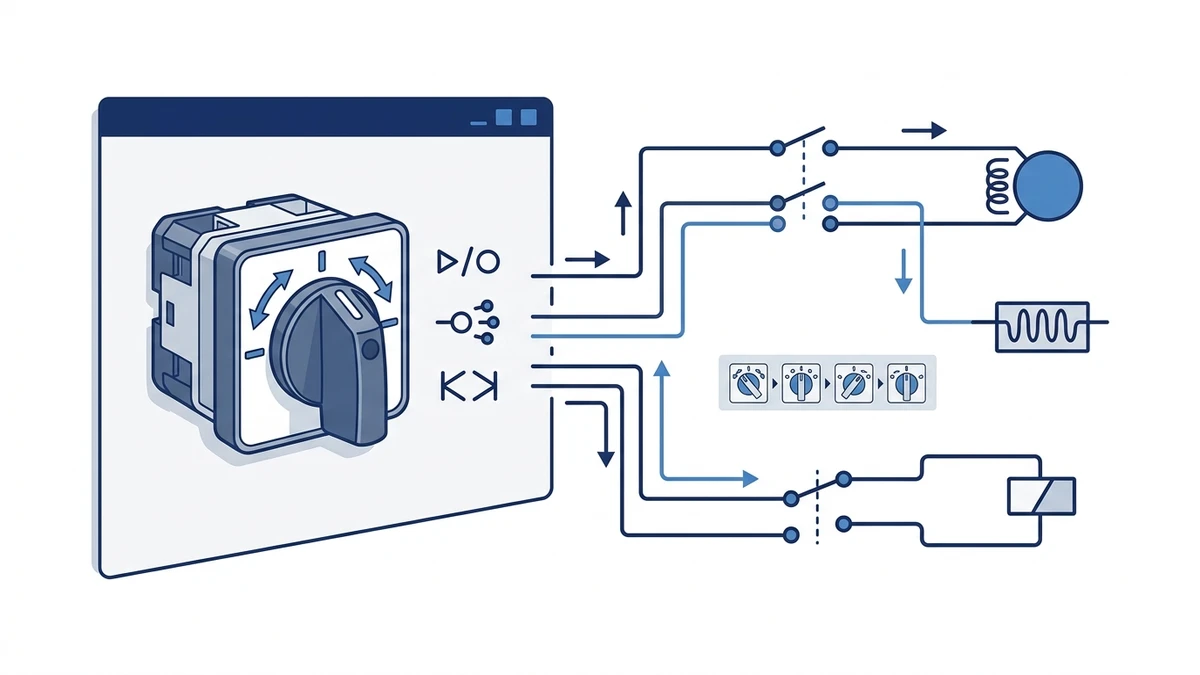
In three-phase motor starter panels, the LW42 is commonly wired as a forward/off/reverse selector. The cam disc sequence opens and closes specific phase pairs to reverse motor rotation without requiring separate contactors for each direction. This arrangement is typical in conveyor drives, small pump stations, and machine tool spindles where the operator needs direct, tactile control over motor state. The switch’s defined detent positions prevent ambiguous intermediate states that could cause phase conflicts.
Control panels that accept both local pushbutton commands and remote PLC signals often use an LW42 as a local/remote transfer switch. In this circuit context, the cam contacts interrupt the PLC command path when the switch is in local mode, and disconnect the local pushbutton circuit when in remote mode. This prevents simultaneous command sources from conflicting. For panels built to IEC 60947-3, this type of selector switch must reliably break the control circuit at rated insulation voltage without contact welding under inductive loads.
HVAC and process ventilation panels frequently use the LW42 as a speed selector for multi-winding motors. Each switch position connects a different winding tap — typically low, medium, and high speed — while the cam geometry ensures only one winding is energized at a time. This interlocking function is built into the cam profile rather than relying on external relay logic, which reduces component count in compact enclosures.
In metering panels, an LW42 configured as a phase selector switch routes individual phase voltages or currents to a single panel-mounted meter. A typical 7-position voltmeter selector covers L1-N, L2-N, L3-N, L1-L2, L2-L3, L3-L1, and off — all within a single switch. This is a space-efficient alternative to installing three separate meters, and it is a common configuration in distribution boards where the LW42 must handle continuous metering transformer secondary currents without contact heating.
For panels requiring a broader switching range or higher pole count, the Série LW28 offers an alternative cam switch platform worth evaluating alongside the LW42.
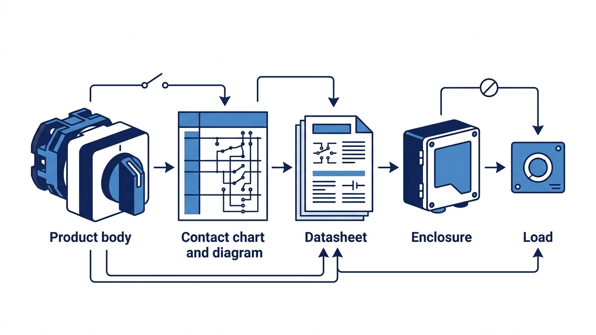
Choosing the correct LW42 configuration before procurement prevents costly rework and panel redesign. Use the checklist below to match your application requirements to a specific variant.
For verified specifications and configuration options, the LW42 rotary cam switch series page provides rated parameters, pole diagrams, and ordering codes. If your application involves adjacent panel components, the broader rotary cam switch range covers companion series including LW28 and SH30 for cross-reference.
For procurement inquiries or OEM configuration support, contact the Shieldhz engineering team directly to confirm lead times, custom cam disc programs, and panel-mount options. Request the current datasheet and any applicable test certificates at the same time — having these documents on file before panel build begins avoids specification disputes during inspection.
Shieldhz treats LW42 selection as a compact changeover engineering check, not a generic selector-switch order. The sales and technical team confirms the exact 20A, 25A, or 32A route, the required contact program, the mounting drawing, handle format, utilization category, and whether the application is a simple selector, measurement selector, forward/off/reverse circuit, or compact changeover duty.
When requesting an LW42 quotation, include the circuit function, number of positions, number of poles, panel space limits, operating voltage, load type, and any CE, UL, CCC, TUV, or other documentation requirement. That gives Shieldhz enough information to return a part-number recommendation with a drawing and contact table instead of leaving the panel builder to infer the switching logic from a catalog title.
A rotary cam switch uses a profiled cam disc to open and close multiple independent contact circuits in a defined sequence across several positions. A standard selector switch typically operates a single contact set between two states. This makes the cam switch the appropriate choice when a single operator action must simultaneously control multiple circuit paths, such as reversing a three-phase motor or selecting between power sources.
The LW42 is rated under IEC 60947-3 for switch-disconnector duty at AC-23A, which covers motor load making and breaking. Whether it qualifies as the sole isolation device depends on local wiring regulations and the fault current rating of the installation. Always verify the prospective short-circuit current at the installation point against the switch’s rated conditional short-circuit current before using it as a main isolator. This value is listed in the product datasheet and must be confirmed with Shieldhz for the specific variant ordered.
The LW42 is rated for a defined number of mechanical operating cycles under standard test conditions — confirm the exact figure from the current datasheet, as it varies by contact configuration. Actual service life in motor switching applications may be shorter if the switch is operated at or near its AC-23A breaking capacity on every cycle, since arc erosion accumulates faster under inductive load conditions. Detent feel and contact resistance measurements at scheduled maintenance intervals are more reliable indicators of remaining service life than cycle count alone.
The LW42 is available in variants that use either a 22mm or 30mm round panel cutout depending on the specific model ordered. Confirm the cutout diameter from the product datasheet before machining. The two sizes are not interchangeable, and the bezel seal that provides IP65 protection is dimensioned to the cutout.
The front-face actuator seal on the LW42 carries an IP65 rating per IEC 60529, which protects against dust ingress and low-pressure water jets. For outdoor installations or wash-down environments, the terminal connections at the rear of the switch are not covered by this rating. A separately rated enclosure is required to protect the wiring side. The rotary cam switch range includes guidance on enclosure pairing for different installation environments.
AC-23A is the IEC 60947-3 utilization category for switching motor loads, defined by the ability to make and break currents with high inductive content — typically up to 10 times the rated current on making. Specifying a switch rated only to AC-21A or AC-22A for motor duty risks contact welding or accelerated erosion because those categories are not tested to the same arc energy levels. Always confirm the utilization category on the switch nameplate and datasheet before installation in a motor circuit.
A three-phase forward/off/reverse circuit requires a 3-pole, 3-position cam disc program where the center position opens all poles and the two outer positions swap two of the three phase connections. The specific cam disc code for this program is listed in the LW42 product documentation. Ordering the wrong program is the most common configuration error in cam switch procurement. Cross-check the pole diagram against your circuit schematic before placing the order, and request confirmation from Shieldhz if the application involves a non-standard switching sequence.
