Industrial Switching &
Control Solutions

Get premium rotary switches, isolators, and panel components directly from the manufacturer.

  • ISO 9001 Certified Quality
  • OEM & Customization Support
  • Fast Global Delivery

Request A Quote

Fill out the form below for pricing, catalogs, and technical support.

Contact Form Demo
Shieldhz GF41 PV DC isolator switch with extended shaft handle assembly for 1500V DC switching projects
GF Series PV DC Isolation

GF41 PV DC Isolator Switch

1500V DC photovoltaic isolator route for cabinet, panel, waterproof box, and higher-pole-count DC switching projects where model code, mounting method, and handle orientation must be specified before quotation.

1500V DCUi Route
16A-55AIth Range
2-10 PolesDC Pole Route
HM / PM / DBMounting
IEC 60947Reference
Certified & Standards-Based
Product Route

1500V DC Switching For Higher Pole Count PV Designs

GF41 is the GF route for 1500V DC PV projects that need more poles, a fixed handle direction, and a confirmed mounting method before quotation.

Use GF41 after the buyer has chosen the PV DC isolator family and needs a buildable model code for drawing and quote review.

Need to compare routes? Start from the PV DC isolator switch pillar, then keep IEC/UL document checks for release.

01

Current and poles

10A-55A route; 2 to 10 pole options.

02

Mounting path

Panel, DIN rail, rod, or H/H box route.

03

Handle direction

Confirm GSA/GSB orientation before drawings.

04

Order files

Use the final code for drawings and certificates.

GF411500V DCMulti-polePV route
Shieldhz GF41 PV DC isolator switch full product view with extended shaft and red rotary handle
1500V DCInsulation voltage
2 to 10 poleConfigurations
H/H routeWaterproof box option
Model Code

GF41 Ordering Structure

A GF41 quotation should not be built from the product photo alone. The ordering line must identify current, pole/contact route, mounting code, and handle direction before the drawing package is confirmed.

GF4132/2-10/H-S-B-T/HM-PM-DB-DC-EL/GSA-GSB
Switch type

GF41 PV DC isolator switch series for photovoltaic DC switching projects.

Rated thermal current

Choose 16A, 25A, 32A, 40A, or 55A according to the string, combiner, or cabinet current route.

Pole count

Use 2, 3, 4, 6, 8, or 10 poles where the circuit route and isolation method require it.

Contact route

Use H, S, B, or T only after the wiring diagram and switching sequence are confirmed.

Mounting and handle

Confirm HM, PM, DB, DC, or EL plus GSA or GSB handle orientation.

If the project needs a weatherproof enclosure, also confirm whether the GF41 route uses the H/H box option or a separate waterproof box family. For broader box comparison, use the waterproof isolator box route before the drawing is frozen.

Technical Data

GF41 Core Specifications From The Catalogue

Use these values for initial selection. Final ordering still needs the selected current, wiring route, mounting code, enclosure route, and approval document check.

Electrical rating

Ui
1500V rated insulation voltage
Uimp
8000V rated impulse withstand voltage
Icw
780A for 1 second
Icm
1200A rated short-circuit making capacity

Current and poles

Ith route
GF41-16, GF41-25, GF41-32, GF41-40, GF41-55
Poles
2, 3, 4, 6, 8, or 10 pole DC route
Contact spacing
8 mm
Life
10000 mechanical operations

Conductor range

Solid/standard
4-16 mm2 maximum conductor section
Flexible
4-10 mm2 flexible conductor
Terminal route
4-10 mm2 flexible conductor with multi-strand terminal
Terminal screw
M4 torque 1.2-1.6 Nm

Mounting torque

Panel screw
ST4.2 torque 0.8-0.9 Nm
Single-hole nut
M16 torque 2.0-2.5 Nm
Knob screw
M3 torque 0.5-0.7 Nm
Nut torque
1.5-2.0 Nm

Operating conditions

Temperature
-40 to +85 deg C operating and storage range
Pollution degree
2
Category
Overvoltage category III
Core IP
IP30 at core / mounting screw level

Standards context

IEC/EN
60947-1 and 60947-3 references in supplied material
AS/NZS
AS 60947.3:2018 and AS/NZS IEC 60947.1:2015
Other refs
UL508I and GB/T14048.3 shown in catalogue text
Use category
DC-PV1 and DC-PV2

Do not select GF41 by voltage label alone. Confirm the DC-PV duty, conductor section, temperature, enclosure, and contact diagram against the final application. For standards review, use the official IEC standards source together with the Shieldhz drawing and certificate package.

Mounting Routes

Installation And Handle Options From The Folder Notes

The supplied docx notes that pictures show handle and mounting form, while current and wiring details must be added through the model code.

PM

Panel mounting

Use where the switch is mounted through a control panel, cabinet door, or local switchgear surface.

D2

DIN rail mounting

Use for internal cabinet layouts when rail position, wire bend radius, and handle clearance are already defined.

D2

DIN rail with rod

Folder note lists D2(135). Confirm the rod length when the handle is remote from the switch body.

H/H

Waterproof box route

Folder note lists H/H(28). Confirm the box family, cable entry, gasket route, and handle position before ordering.

If the environment requires an outdoor local disconnect, compare this route with Shieldhz waterproof isolator boxes before freezing the GF41 drawing.

Specification Drawings

Waterproof Box Dimension References

Use these dimension drawings as installation references for GF41 waterproof-box routing. Review them when the project needs to confirm enclosure footprint, body depth, handle projection, cable-entry clearance, service access, and cabinet space before quotation. The drawing reference should be matched to the selected current, pole count, H/H box family, handle orientation, cable-entry plan, and inspection requirement; it does not replace the final approval drawing issued against the confirmed GF41 model code.

Ordering note: send the GF41 model route to Shieldhz when procurement needs approval files before order release. The final drawing package should confirm the enclosure family, selected handle route, cable entry, and production document requirements before manufacturing is confirmed.

Selection Matrix

How To Route A GF41 Inquiry

GF41 should not be quoted from a product picture alone. Route the inquiry by current, pole count, contact route, mounting method, and handle orientation.

1

Confirm current

Choose 16A, 25A, 32A, 40A, or 55A from the PV circuit current and derating requirement.

2

Confirm pole route

Use 2, 3, 4, 6, 8, or 10 poles according to the isolation diagram and wiring method.

3

Confirm contact code

Choose H, S, B, or T after reviewing the required circuit diagram and switching sequence.

4

Confirm installation

Define HM, PM, DB, DC, EL, panel, D2 rail, D2 rod, or H/H waterproof-box mounting.

5

Confirm documents

Request the matching 2D drawing, certificate copy, label data, and inspection route before production.

For fast review, send the target DC voltage, current, pole/contact route, mounting method, handle orientation, enclosure requirement, quantity, certification market, and lead-time target. If the project is not clearly GF41, compare GF40 enclosed string isolation and GF51 DIN rail or cabinet routing first.

FAQ

GF41 PV DC Isolator FAQ

These answers focus on selection and quotation details for engineers, panel builders, and PV equipment buyers.

What is GF41 used for?

GF41 is used for photovoltaic DC isolation where a 1500V DC route, higher pole count, and defined mounting or handle codes are required. It is normally reviewed for cabinet, panel, waterproof-box, or switchgear integration rather than a simple off-the-shelf picture match.

Is GF41 a 1500V DC isolator switch?

Yes. The supplied GF41 catalogue data lists 1500V rated insulation voltage and DC-PV1 / DC-PV2 utilization category references. The final selection still needs confirmation of current, pole count, contact route, conductor section, and the project approval document package.

Which GF41 current ratings are available?

The catalogue table lists GF41-16, GF41-25, GF41-32, GF41-40, and GF41-55. These correspond to 16A, 25A, 32A, 40A, and 55A rated thermal current routes. Use the PV circuit current and derating requirement before selecting the size.

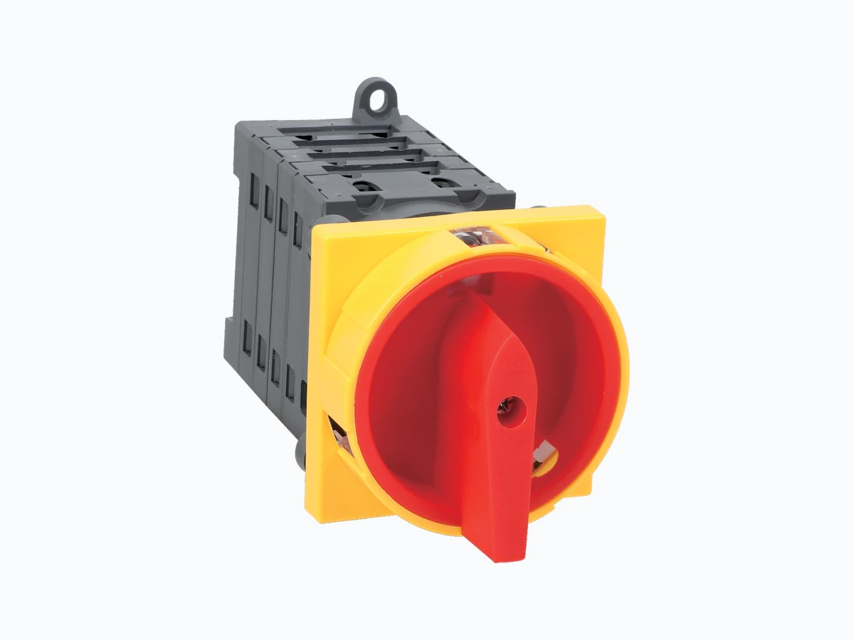
How do I choose the GF41 pole and contact route?

Start from the circuit diagram, not from the face label. GF41 material lists 2, 3, 4, 6, 8, and 10 pole routes plus H, S, B, and T contact routes. Confirm the switching sequence and wiring diagram before quoting.

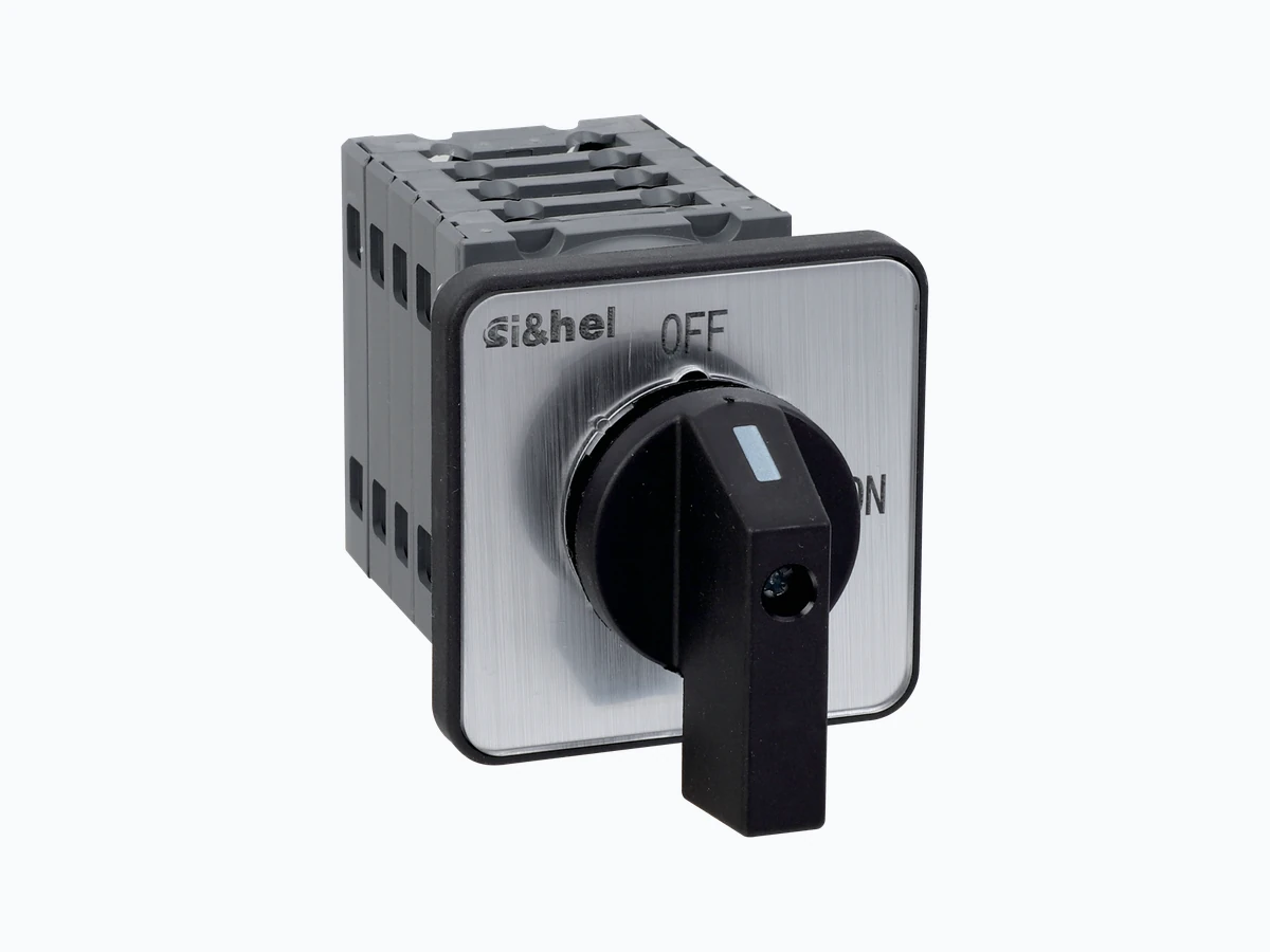
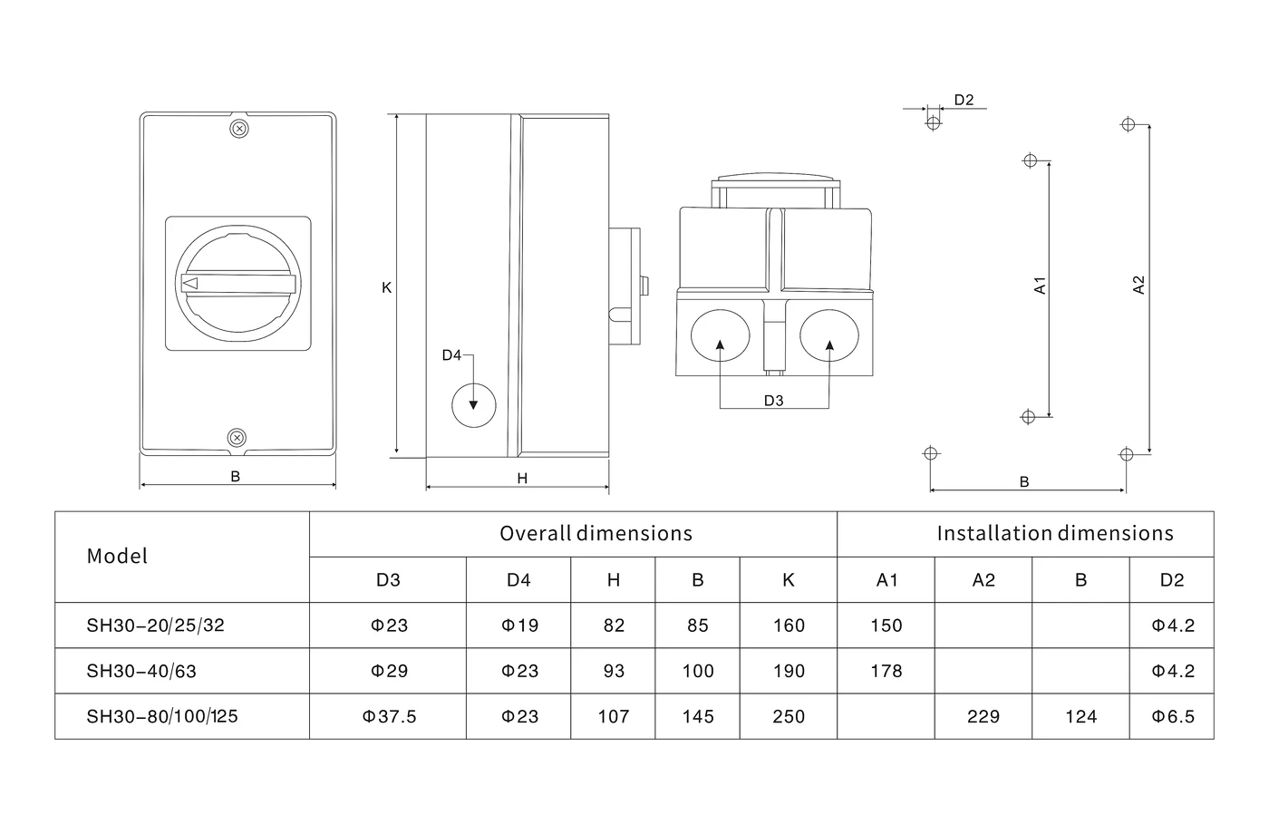
What mounting options should be checked for GF41?

Check the mounting code and the folder note together. The ordering structure lists HM, PM, DB, DC, and EL, while the folder note references panel mounting, D2 DIN rail mounting, D2 rod mounting, and H/H waterproof box mounting.

What is the difference between GF41, GF40, and GF51?

GF41 is the higher-pole-count 1500V DC cabinet, panel, or box route. GF40 is stronger for enclosed string-level isolation with M20, M25, or MC4 connection routes. GF51 is the better route for DIN rail or IP20 cabinet installation.

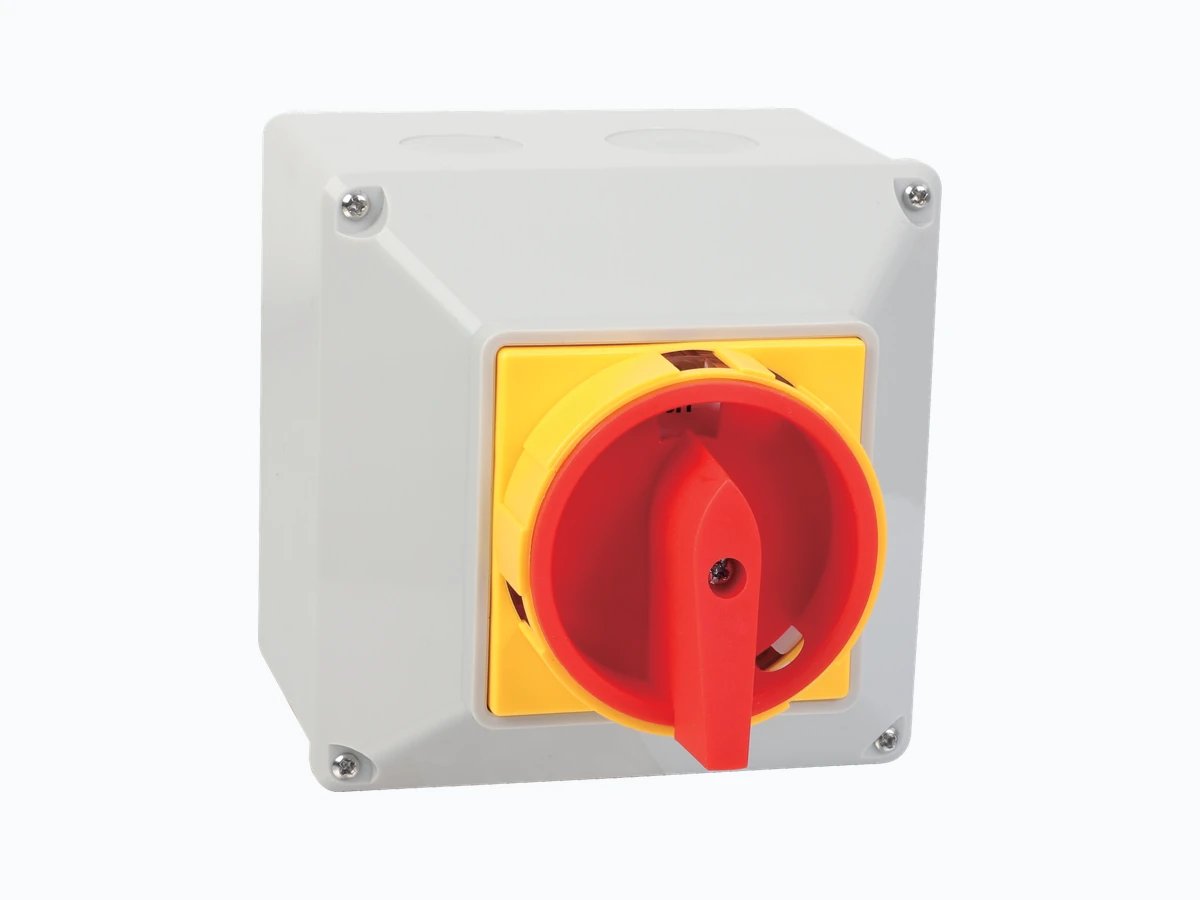
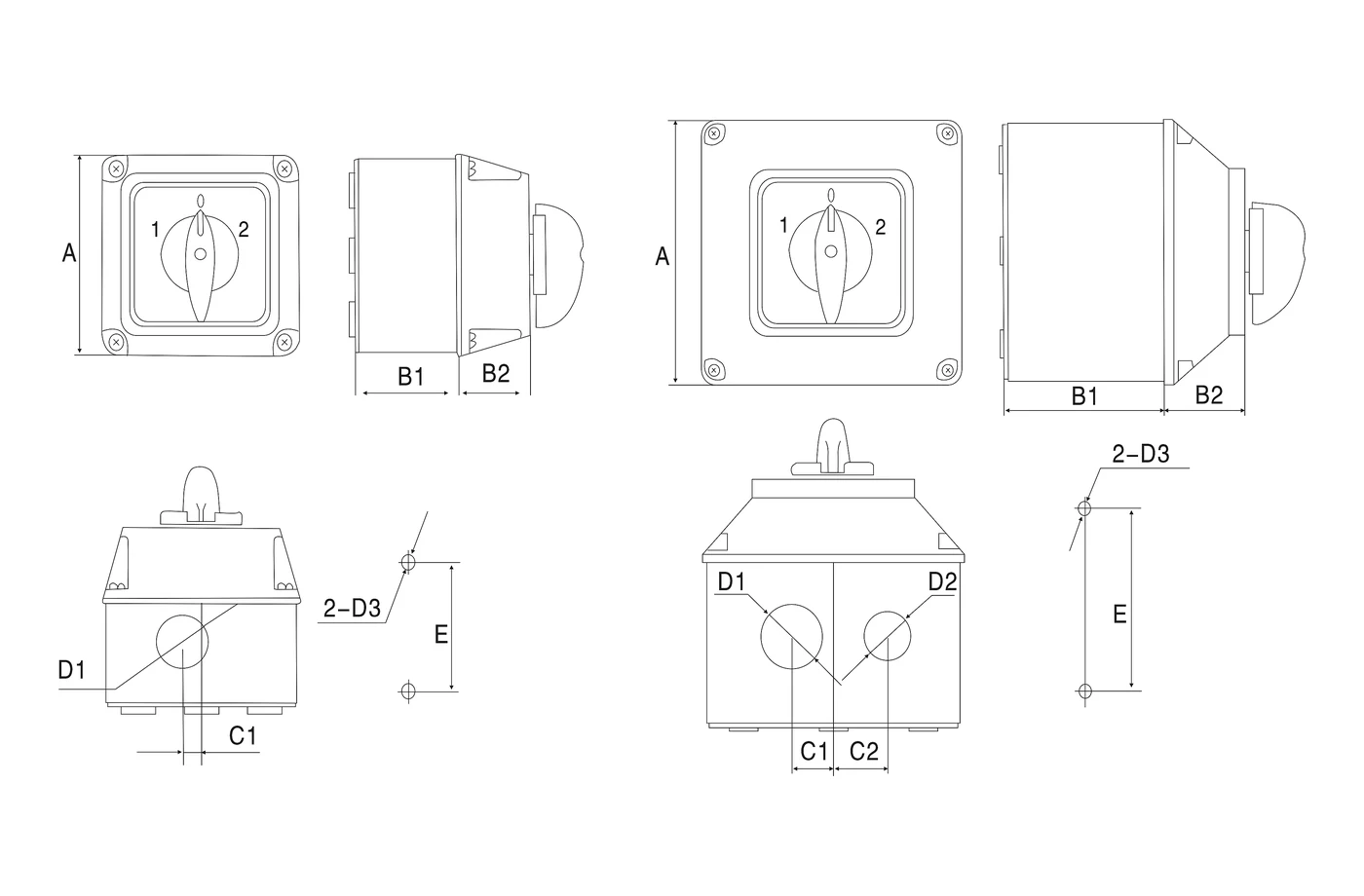
Can GF41 be used in a waterproof box?

GF41 material includes an H/H waterproof-box route and related dimension references, but the enclosure family must be confirmed. Check box size, cable entry, gasket route, handle position, and inspection access before treating it as an outdoor disconnect package.

What information is needed for a GF41 quotation?

Send the target DC voltage, operating current, pole count, contact wiring route, mounting method, handle orientation, enclosure requirement, quantity, certification market, and lead-time target. Add a drawing or circuit diagram if the contact route is not standard.

White transparent line art of Shieldhz GF40 GF51 and GF41 PV DC isolator switches for CTA background
Inquiry

Send GF41 Requirements

Share target DC voltage, operating current, pole/contact route, mounting method, handle orientation, enclosure route, quantity, target approval market, and delivery schedule. Shieldhz will confirm the GF41 model code, drawing, certificate file, MOQ, and document package before quotation.

Contact Form Demo

For direct email, contact [email protected] or [email protected].