Industrial Switching &
Control Solutions

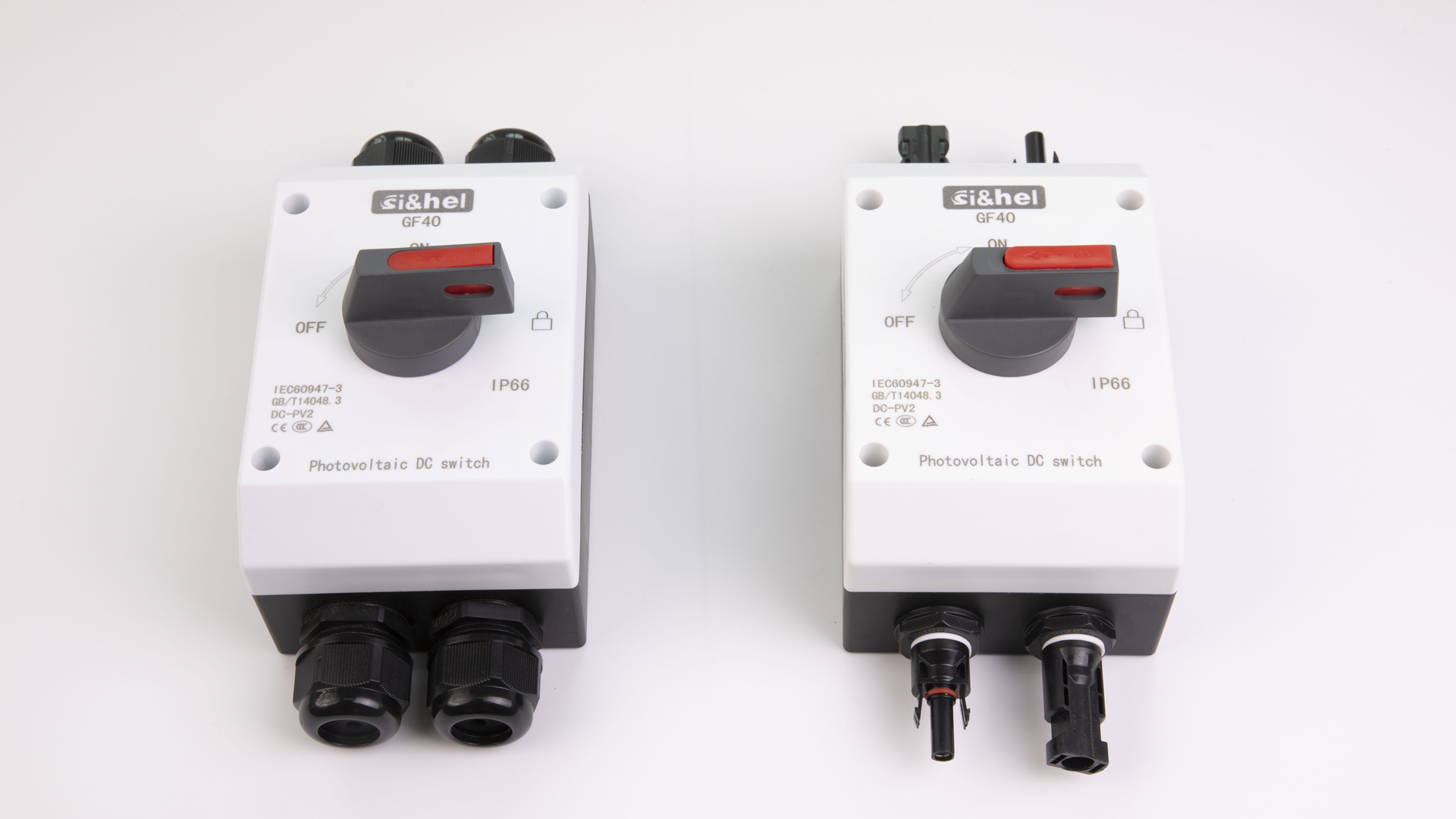
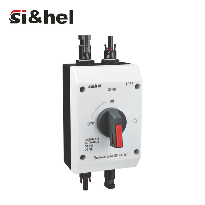
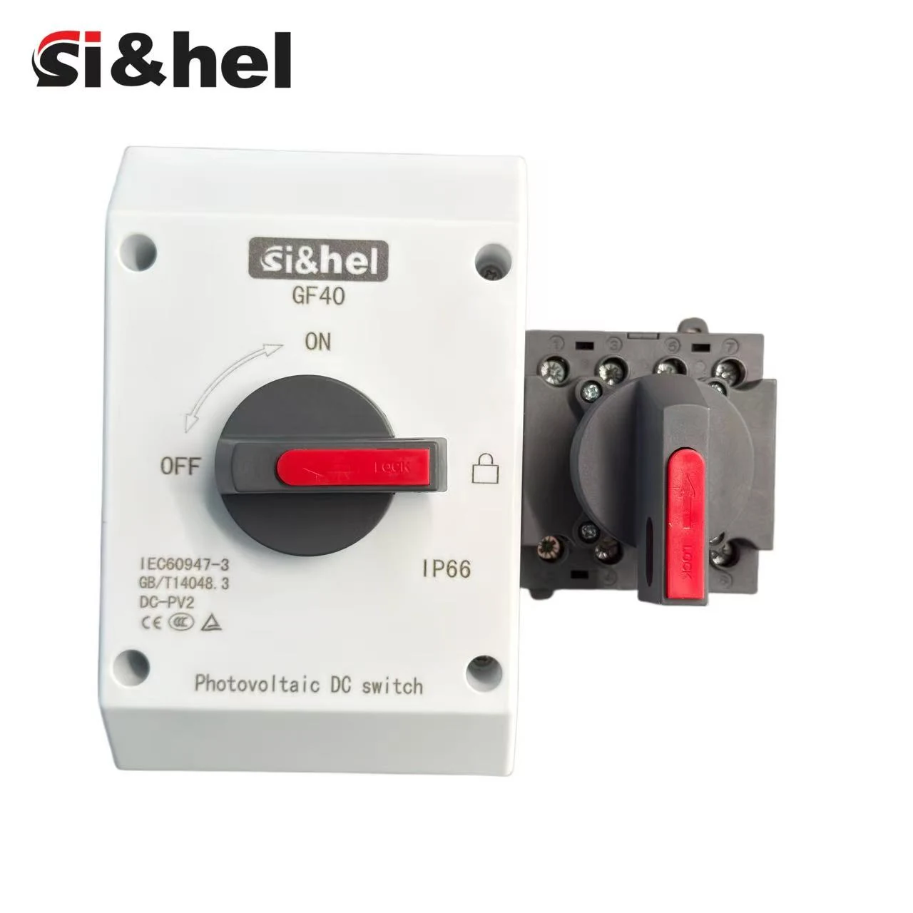
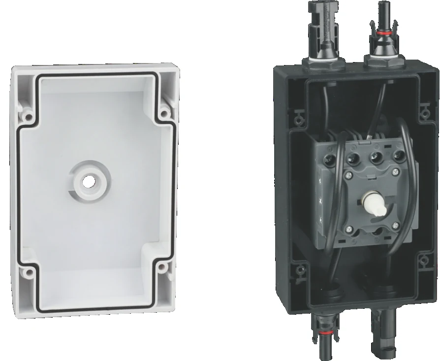
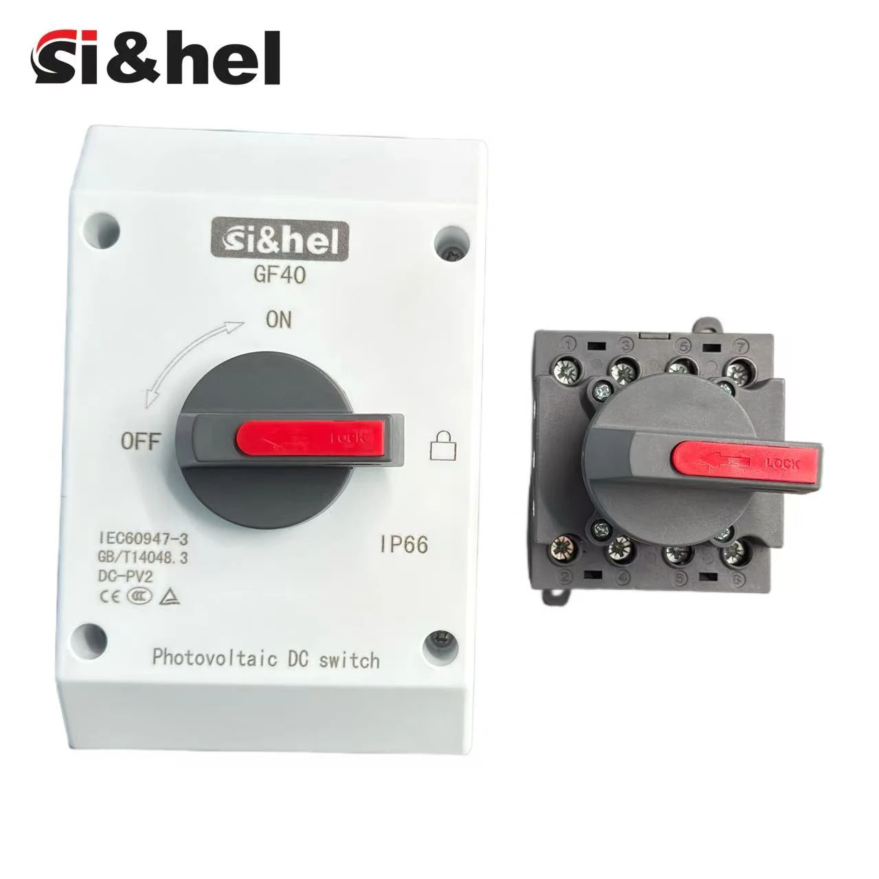
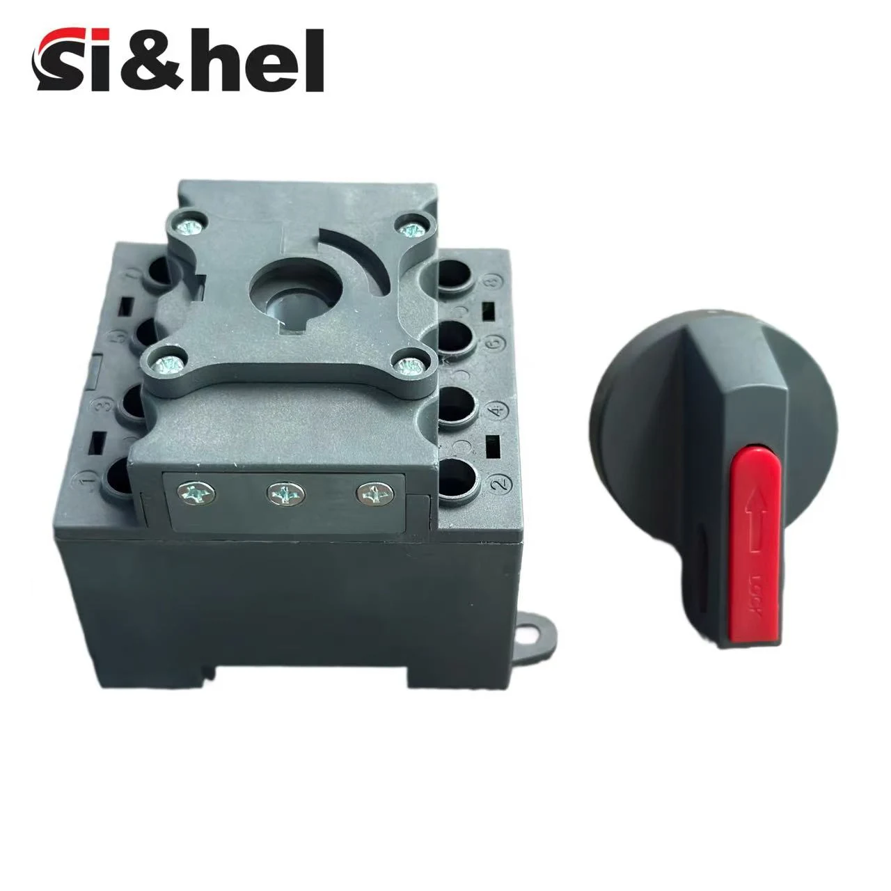
Get premium rotary switches, isolators, and panel components directly from the manufacturer.

  • ISO 9001 Certified Quality
  • OEM & Customization Support
  • Fast Global Delivery

Request A Quote

Fill out the form below for pricing, catalogs, and technical support.

Contact Form Demo
Shieldhz GF40 PV DC isolator switch IP66 waterproof box and panel mount variants
GF Series PV DC Isolation

GF40 PV DCIsolator Switch

IP66 enclosed PV DC isolator for string isolation, rooftop service disconnects, and inverter-side DC switching, with M20, M25, or MC4 cable entries.

1000-1200VDCStandard Route
10A-32AEnclosed Current
IP66Box Protection
M20 / M25 / MC4Connection
IEC 60947-3Standard
Certified & Standards-Based
Product Route

Outdoor PV String Isolation With A Serviceable IP66 Box

GF40 fits outdoor PV circuits where the isolator sits near solar strings, inverter DC inputs, or rooftop equipment and the enclosure must tolerate exposed conditions. The catalogue defines arc-extinguishing contacts, OFF-position cover removal, M20/M25/MC4 cable entries, and selectable contact wiring.

Arc controlEach pole contact includes arc-extinguishing structure for DC switching duty.
Fast breakCatalogue notes list approximately 2 ms contact opening for the enclosed route.
Cover interlock logicThe cover is removable only in the OFF position, so wiring checks stay tied to the isolation state.
Connector choicesM20, M25, and MC4 cable entries fit conduit, gland, and direct PV string connection layouts.
GF40 IP66 PV DC isolator switch with MC4 connectors installed for solar string isolation
Technical Data

GF40 Core Specifications From The Catalogue

Start with these catalogue values, then confirm voltage, current, pole count, contact wiring, connector type, and approval documents before release.

ParameterGF40 enclosed route
Rated voltage1000VDC-1200VDC standard catalogue range; 1500VDC requires model and document confirmation
Rated current10A, 16A, 20A, 25A, 32A standard enclosed ratings
Ingress protectionIP66 enclosed switch box
Connection typeM20, M25, MC4
Operating temperature-25 deg C to +85 deg C
Utilization referencesDC-PV1, DC-PV2, DC-21B by wiring configuration and voltage row
StandardsIEC 60947-3; AS/NZS 60947.3:2015
Contact Routes

GF40 Model Code And Wiring Configuration

The catalogue separates current rating from contact wiring. Send the configuration code so terminal direction and pole count are unambiguous.

2

2-pole

Basic two-pole DC isolation for simple string or equipment disconnects.

2H

2-pole / 4 parallel poles

Parallel-contact layout for current levels and switching duty that require the 2H configuration.

4

4 parallel poles

Four-pole layout for projects that need grouped DC contact paths.

4S

Input top, output bottom

Four-pole wiring with top input and bottom output.

4B

Input and output bottom

Four-pole wiring for bottom-side input and output.

4T

Input and output top

Four-pole wiring for top-side input and output.

Rating Route

Common GF40 Model Families

Catalogue ratings vary by contact configuration. This summary keeps the common model families visible while preserving the details needed for RFQ review.

2P/H enclosed routeTwo-pole
ModelsGF40-16/2P/H, GF40-25/2P/H, GF40-32/2P/H
Rating noteDocumented across 600V, 800V, 1000V, and 1200V rows. At 1000V, catalogue rows include 9A, 11A, and 16A values by model.
Use caseStandard two-pole PV string or equipment isolation.
2H/H parallel routeParallel
ModelsGF40-16/2H/H, GF40-25/2H/H, GF40-40/2H/H
Rating noteHigher-current parallel-contact route. Confirm usable voltage/current row before ordering.
Use caseProjects requiring higher switching duty in a two-pole arrangement.
4P/H routeFour-pole
ModelsGF40-16/4P/H, GF40-25/4P/H, GF40-32/4P/H
Rating noteFour-pole route with separate series count requirements in the rating table.
Use casePV strings or equipment requiring four contact paths.
4S / 4B / 4T routeWiring direction
ModelsGF40-16/4S/H to GF40-32/4T/H
Rating noteConfiguration depends on whether input and output are routed at top or bottom.
Use casePanel layouts where cable direction and contact routing must be specified.
DIN rail / main switch routeCabinet
ModelsGF40 DIN rail 16A, 25A, 32A
Rating noteCatalogue page references DC21B 16A, 25A, 32A to 1500V DC for this route.
Use caseCombiner cabinet or internal panel integration.

For 1500V DC requirements, confirm the exact model code, wiring drawing, and certificate package before the purchase specification is approved.

Dimensions

Enclosure And DIN/Main Switch Form Factors

The GF40 series appears in enclosed IP66 box form and in DIN rail or mechanism form. Select the drawing that matches the physical installation.

GF40 IP66 waterproof box and bare mechanism showing two installation form factors
IP66 enclosure formCatalogue drawing lists a 161.0 mm by 104.0 mm enclosure face, with 144.2 mm by 87.6 mm mounting centers and 76.3-111.1 mm depth range by assembly form.
DIN rail / mechanism formCatalogue drawing lists 65.5 mm width, 78.0/71.2 mm body height references, 63.7 mm body depth, and 45.0 mm handle projection reference.
Mounting noteCheck the final 2D drawing for hole pattern, cable gland position, handle clearance, and enclosure depth before panel or box fabrication.
Installation Detail

What To Confirm Before Installing GF40

Field issues usually come from selecting the electrical rating, cable entry, and enclosure treatment separately. Confirm them as one assembly before panel or rooftop installation.

GF40 IP66 enclosure opened to show internal DC isolator mechanism and cable connection route

Internal route

Confirm internal wiring, terminal access, cable bend space, and cover removal logic before releasing the enclosure drawing.

GF40 PV DC isolator front label with IEC60947-3 DC-PV2 IP66 markings

Marking and rating

Match the face label, model code, utilization category, and project voltage/current row before release to procurement.

GF40 panel mounting bracket and rotary handle assembly components

Mounting hardware

Check handle projection, bracket route, panel thickness, screw torque, and wiring clearance before cabinet layout.

RFQ note: specify whether the GF40 unit will be installed as a rooftop string disconnect, inverter-side DC isolation point, combiner-box isolator, or cabinet-mounted mechanism. This tells Shieldhz whether the quote needs IP66 enclosure hardware, MC4 connectors, M20/M25 cable glands, label language, certificate files, or a drawing package. For replacement projects, include the existing enclosure cutout, cable direction, handle position, and any local lockout requirement so the new GF40 configuration can be checked against the installed panel instead of only the catalogue table. For OEM or repeat orders, keep the approved wiring code and enclosure drawing tied to the purchase specification so later batches do not drift from the tested configuration.
Visual Selection Check

Map GF40 Before Quotation

Specify GF40 by checking the electrical rating and enclosure details together. Confirm voltage, contact code, cable entry, and document requirements before the quote is prepared.

For installed-base replacement, send photos of the current enclosure, handle position, cable entry, and face label so Shieldhz can compare the requested GF40 route with the real mounting condition.
1 Voltage And CurrentConfirm 1000VDC, 1200VDC, or a validated 1500VDC model path plus the required 10A to 32A current row.
2 Contact CodeChoose 2P, 2H, 4P, 4S, 4B, or 4T from the wiring direction, pole count, and input/output layout.
3 Enclosure EntryMatch the IP66 box with M20, M25, or MC4 entry, gasket treatment, and cover-removal access.
4 DocumentsRequest drawing, label language, certificate file, target market, quantity, and lead-time confirmation together.
FAQ

GF40 PV DC Isolator FAQ

What is the standard voltage range for GF40?

The GF40 enclosed PV DC isolator is documented for 1000VDC to 1200VDC applications. For 1500VDC projects, confirm the exact GF model path with the required model code, rating table, and approval documents.

Which connection types are available?

GF40 can be configured with M20, M25, or MC4 cable-entry options depending on enclosure, cable entry, and PV string connection requirement. Confirm the connector or gland before the enclosure drawing is released.

What does 2H, 4S, 4B, and 4T mean?

These codes describe contact and wiring configuration. 2H is a 2-pole layout using four parallel poles. 4S, 4B, and 4T describe 4-pole routes with different top and bottom input/output arrangements.

Is GF40 suitable for outdoor rooftop solar?

Yes. The enclosed GF40 version is used for rooftop or exposed PV string isolation when the project requires an IP66 enclosure, suitable cable-entry protection, and a lockable local disconnect point near the solar equipment.

What is the difference between GF40 and GF51?

GF40 is mainly positioned for enclosed string-level isolation with M20, M25, or MC4 cable-entry options. GF51 is usually the better fit when the project needs DIN rail mounting, IP20 cabinet installation, or a wider 300V to 1500V DC rating table.

Can GF40 be used for 1500V DC solar systems?

Do not assume a 1500V DC project from the front label alone. GF40 can be reviewed for a 1500V requirement, but Shieldhz should confirm the exact contact configuration, rating row, certificate requirement, and whether GF41 or GF51 is more suitable.

What information is needed for a GF40 quotation?

Send DC voltage, current, pole configuration, wiring layout, enclosure or cable-entry type, installation location, target certification market, quantity, requested delivery schedule, and whether drawings or certificate files are needed.

White transparent line art of Shieldhz GF40 GF51 and GF41 PV DC isolator switches for CTA background
Inquiry

Send GF40 Requirements

Share DC voltage, operating current, contact code, cable-entry type, IP66 enclosure requirement, quantity, target certification market, and delivery schedule. Shieldhz will confirm the GF40 model code, drawing, certificate file, MOQ, lead time, and document package before quotation.

Contact Form Demo

For direct email, contact [email protected] or [email protected].