Uma chave comutadora é um dispositivo de comutação manual usado para conectar uma carga a uma de duas fontes de alimentação ou caminhos de circuito diferentes. Em painéis industriais, ele geralmente é construído com uma lógica de chave de came rotativa, como I-0-II, para que o operador possa selecionar a fonte 1, OFF ou a fonte 2 sem conectar as duas fontes.
Os compradores industriais geralmente encontram chaves de comutação quando uma máquina precisa de uma escolha manual clara entre rede elétrica e gerador, utilitário e desvio de UPS ou dois alimentadores de entrada separados. Se você já analisou o cenário mais amplo de componentes em Guia de componentes de controle industrial e os princípios básicos de operação em O que é um interruptor de came rotativo?, Este artigo relaciona essas ideias à seleção de fontes e ao design do painel.
O significado básico de uma chave comutadora
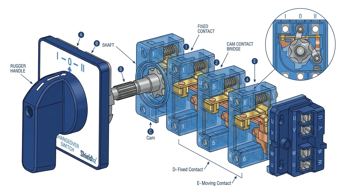
Uma chave de comutação muda o circuito conectado de uma entrada para outra. A forma mais comum em painéis de controle e distribuição de baixa tensão é um dispositivo rotativo manual com posições fixas. Internamente, um mecanismo de came abre e fecha conjuntos de contatos em uma sequência definida à medida que a alavanca gira.
Para muitos construtores de painéis, “chave de comutação” significa:
Uma carga
Duas fontes ou caminhos possíveis
Um selecionado de cada vez
Uma posição OFF deliberada em muitos projetos
Lógica de comutação mecânica que evita a sobreposição quando especificada como break-before-make
Isso torna o dispositivo útil quando um operador ou técnico de manutenção precisa de uma seleção manual positiva e visível da fonte em vez de um controle automático.
Conceito básico de comutação: uma carga, duas fontes, um caminho selecionado.
Como funciona a seleção manual de fontes de suprimento
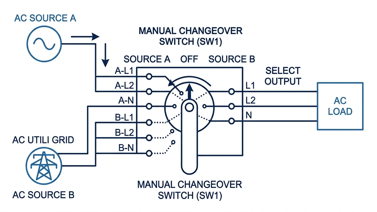
A seleção manual de fonte é exatamente o que parece: uma pessoa gira a alavanca para escolher qual circuito de entrada alimenta a carga de saída. A chave não detecta a perda da rede elétrica, não monitora a tensão nem faz a transferência por si só. Ela só muda de estado quando é acionada.
Uma sequência típica é:
Posição I: carga conectada à fonte 1
Posição 0: carga desconectada
Posição II: carga conectada à fonte 2
Esse é o arranjo clássico I-0-II. É comum em montagens operadas por came porque dá ao usuário um estado claro de centro-off antes de selecionar a fonte alternativa. Para as equipes de manutenção, essa posição central pode apoiar a prática de bloqueio, testes e reduzir a confusão durante o trabalho de manutenção, dependendo do projeto geral do painel.
Compreensão da lógica I-0-II
I-0-II é uma das marcações de alça mais conhecidas para o serviço de troca manual.
I = primeira fonte ou primeiro caminho do circuito
0 = OFF ou posição de comutação isolada
II = segunda fonte ou segundo caminho do circuito
O ponto importante não é apenas a rotulagem. O diagrama de contato interno define o que acontece em cada posição. Duas chaves podem ter a inscrição I-0-II na frente, mas ter diferentes arranjos de polos, lógica de ponte e classificações de corrente.
Por exemplo, uma chave comutadora pode ser projetada para comutar:
2 polos para linha monofásica e neutro
3 polos para linhas trifásicas
4 polos para trifásico mais neutro
Outra pode incluir contatos auxiliares extras para indicação ou sinalização de intertravamento. É por isso que apenas a marcação da alça nunca é suficiente para a aquisição.
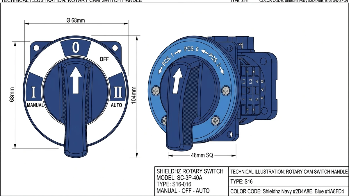
A marcação da alça I-0-II mostra a fonte 1, OFF e a fonte 2.
Por que é importante quebrar antes de fazer
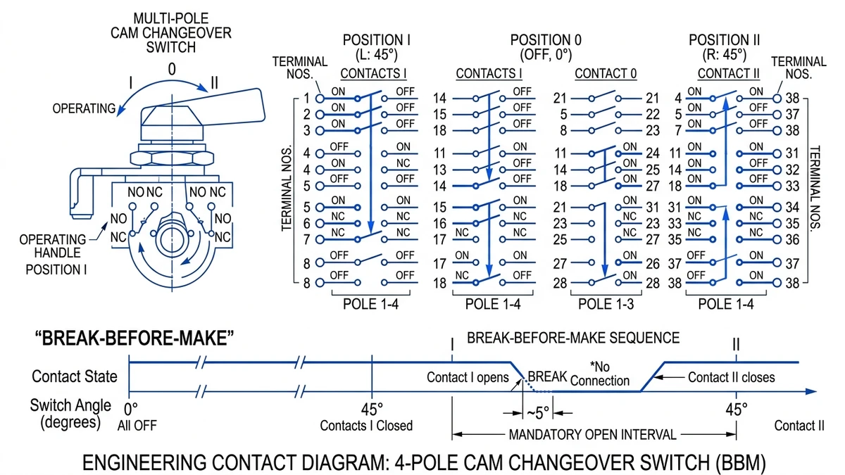
Para a seleção de fontes, a característica de comutação mais segura e importante é a de interrupção antes da criação. Isso significa que o primeiro circuito abre antes que o segundo circuito feche. Em termos práticos, a carga é momentaneamente desconectada durante a transição, o que ajuda a evitar o paralelismo de duas fontes por meio da chave.
Isso é importante quando as duas fontes nunca devem ser conectadas juntas, por exemplo:
Utilitário e gerador
Dois alimentadores independentes
Diferentes secundários de transformadores
Caminhos alternativos de alimentação da máquina
Se uma chave fosse do tipo "make-before-break", a nova fonte poderia se conectar antes que a fonte antiga se desconectasse. Em uma aplicação de troca de fonte, essa sobreposição pode ser inaceitável ou perigosa, a menos que o sistema seja especificamente projetado para isso.
Ao analisar uma chave de comutação, confirme a sequência de comutação na tabela de contatos ou na folha de dados técnicos. Não presuma que todos os dispositivos rotativos usam a mesma lógica de transição.
Chave comutadora vs. chave de transferência
Às vezes, esses termos são misturados, mas nem sempre são idênticos nas discussões dos compradores.
Uma chave comutadora manual é geralmente um dispositivo operado manualmente que seleciona uma fonte ou outra. Uma chave de transferência é um termo mais amplo que pode incluir projetos manuais ou automáticos. Em muitas instalações, “ATS” refere-se a uma chave de transferência automática que detecta falhas na fonte e transfere a carga de acordo com a lógica e o intertravamento programados.
Principais diferenças:
Chave de comutação:
Geralmente manual
Operação baseada em posição
Geralmente, um came rotativo ou mecanismo semelhante
Arquitetura de controle mais simples
Chave de transferência:
Pode ser manual ou automático
Pode incluir detecção de tensão, temporizadores de atraso, intertravamentos mecânicos e elétricos
Frequentemente selecionado para sistemas de energia de reserva
Portanto, todo seletor de fonte manual não é automaticamente equivalente a uma solução de transferência totalmente automática. Se a aplicação precisar de comutação autônoma após uma falha na rede elétrica, uma chave comutadora de came manual não substitui um pacote ATS adequadamente projetado.
Chave comutadora vs. chave seletora
Uma chave seletora escolhe uma função de controle, mas nem sempre alterna os caminhos de energia. Muitas chaves seletoras operam circuitos de controle de baixa corrente para seleção de modo, como HAND-OFF-AUTO, LOCAL-REMOTE ou seleção de velocidade. Uma chave de comutação, por outro lado, geralmente comuta a carga real ou os condutores do alimentador, dependendo de sua classificação e da função pretendida.
Os dois dispositivos podem parecer semelhantes na parte frontal porque ambos podem usar alças giratórias. A diferença está no serviço elétrico, na estrutura do polo, no tamanho do contato, no escopo da certificação e na intenção da aplicação.
Se estiver comprando para uma lista técnica de painel, faça estas perguntas:
Isso é sinal de controle de comutação ou condutores de energia?
Qual é a categoria operacional atual e de utilização?
A aplicação exige características de desconexão ou de chave seccionadora?
A sobreposição de fontes é proibida?
O neutro está ligado?
Essas perguntas geralmente separam um dispositivo seletor para serviços leves de um conjunto de chaveamento de comutação genuíno.
Diagramas de contato do interruptor de came: como lê-los
O diagrama de contatos é o coração da especificação de uma chave comutadora. Ele informa quais pares de contatos são fechados em cada posição da alavanca. Para uma chave de came, o perfil interno do came controla essa sequência.
Os elementos típicos de um diagrama incluem:
Terminais numerados
Grupos de polos
Tabela de posições
Estado ON/OFF por ângulo da alça ou marcação
Às vezes, uma notação de curto-circuito ou não curto-circuito
Um seletor de fonte simples de 3 posições pode ser exibido:
Posição I: terminais da fonte 1 fechados para carga
Posição 0: todos os contatos de fonte para carga abertos
Posição II: terminais da fonte 2 fechados para a carga
Para aplicações trifásicas, essa lógica é repetida em vários polos. Se o neutro também precisar ser transferido, um quarto polo poderá ser incluído. Algumas aplicações exigem neutro não comutado, portanto o diagrama deve corresponder à filosofia do sistema.
A marcação da alça frontal é apenas a interface do usuário. A verdade real da engenharia está no diagrama de fiação e na programação de contatos.
Os diagramas de contato definem o comportamento real de comutação por trás da marcação da alça.
Padrões e cuidados com a classificação
Para dispositivos de comutação de baixa tensão, as estruturas da IEC são importantes, mas somente quando o produto é classificado e documentado para o serviço pretendido. A IEC 60947-3 é relevante para chaves, seccionadores, chaves seccionadoras e unidades de combinação de fusíveis em aplicações de baixa tensão quando o dispositivo é projetado e testado para esse serviço. Os compradores devem verificar a classificação exata do produto, a categoria de utilização, a configuração dos polos e a documentação, em vez de presumir que todas as chaves rotativas são qualificadas da mesma forma.
Para as equipes de compras de OEM, a revisão dos padrões deve incluir:
Tensão operacional nominal
Corrente operacional nominal
Categoria de utilização
Número de postes
Adequação do isolamento ou da seccionadora, se necessário
Expectativas de coordenação de curto-circuito na montagem completa
Marcações e documentos de certificação para o modelo específico
Isso é especialmente importante porque uma família de produtos pode incluir versões para diferentes tarefas, enquanto os requisitos do painel permanecem fixos.
Onde a rota LW28 se encaixa
A Shieldhz fabrica produtos de interruptor de came rotativo e componentes de controle relacionados na província de Zhejiang, China, com operações da empresa estabelecidas em 2014. A linha de produtos inclui chaves de came, chaves isoladoras, botões de pressão, luzes indicadoras e blocos de terminais. Para os compradores que estão explorando o hardware de seleção de fontes dentro dessa faixa, a principal rota familiar é a Categoria de interruptor de came rotativo.
Para projetos de painéis com muita documentação, a vantagem prática não é apenas a variedade de produtos, mas o suporte de engenharia repetível. A Zhejiang Shihe Electric Co., Ltd. opera uma base de fabricação de mais de 5.000 m2 com mais de 100 funcionários e mais de 40 máquinas de produção e oferece suporte à documentação de conformidade industrial comum, como ISO9001, RoHS, CE, TUV, UL, UKCA, CCC e CB, quando aplicável ao produto específico. Os compradores ainda devem solicitar os documentos atuais para o modelo e a classificação exatos, pois as aprovações podem variar de acordo com a configuração.
Dentro dessa categoria, a série LW28 é o caminho prático para avaliar as configurações de seleção de fonte rotativa manual, dependendo dos polos necessários, das classificações de corrente, do estilo de montagem e da lógica de contato. Ponto de partida do produto: Chaves de came rotativo LW28.
Isso não significa que todos os aplicativos devam usar um modelo como padrão. Significa que o comprador deve mapear o aplicativo para:
Serviço elétrico
Lógica de posição
Corte do painel e método de montagem
Tipo de alça
Legenda da placa frontal
Aprovações e documentos de teste necessários
Estilo do terminal de fiação e tamanho do condutor
Para as equipes de engenharia, o caminho certo não é “encontrar qualquer interruptor I-0-II”. É “encontrar o programa de contato exato e a capacidade nominal”.”
Aplicações industriais comuns
Uma chave de comutação manual pode ser usada em aplicações como:
Seleção do fornecimento da concessionária ou do gerador para uma carga local
Escolha entre transformadores de controle redundantes
Comutação de um circuito de motor entre caminhos de controle alternativos quando o projeto permitir
Seleção de alimentação normal ou de manutenção em um subpainel de máquina
Escolha de uma das duas fontes de teste em uma configuração de serviço
Os limites da aplicação ainda são importantes. Alguns problemas de transferência de fonte exigem contatores intertravados, comutação motorizada ou equipamento de transferência formal em vez de uma chave de came operada manualmente. O projetista do painel deve combinar o tipo de chave com o perfil de risco e o método de operação.
Lista de verificação de seleção para compradores e construtores de painéis
Use esta lista de verificação antes de liberar um pedido de compra:
Arquitetura de origem
Quais são as duas fontes?
Eles devem permanecer totalmente isolados uns dos outros?
Contagem de polos
2P, 3P ou 4P?
O neutro está ligado?
Lógica de posição
I-0-II ou outra sequência?
O centro OFF é obrigatório?
Tipo de transição
É necessário quebrar antes de fazer?
Classificações elétricas
Tensão, corrente, frequência, categoria de utilização
Forma mecânica
Montado em porta, montado em painel, montado na base
Comprimento do eixo e compatibilidade com o kit de alça
Meio ambiente
Estratégia de entrada no painel, temperatura, contaminação, vibração
Documentação
Folha de dados
Diagrama de contato
Dimensões gerais
Orientação de torque terminal
Certificados e declarações
Análise de conformidade
Confirmar a relevância dos padrões para o modelo exato e o caso de uso
Capacidade de manutenção
Acesso ao terminal, etiquetagem, estratégia de reposição
A seleção deve corresponder à lógica do contato, aos polos, à classificação e aos detalhes de montagem.
Erros frequentes de especificação
Os erros mais comuns são básicos, mas caros:
Compra somente por etiqueta de manuseio
“I-0-II” não confirma o programa de contato interno.
Ignorando o comportamento break-before-make
Esse pode ser um problema crítico de isolamento da fonte.
Contagem de polos incorreta
O trifásico mais o neutro geralmente é interpretado erroneamente como 3P.
Supondo que qualquer chave seletora possa fazer a troca de energia
Os dispositivos de controle e de potência não são intercambiáveis.
Expectativas de desconexão ausentes
Se o isolamento for parte do requisito, verifique a capacidade e as marcações exatas do produto.
Verificação insuficiente da documentação
Um pacote de folha de dados limpo economiza tempo durante a montagem, inspeção e substituição do painel.
Esquecimento dos detalhes da alça e da montagem
As peças de acoplamento da porta, os kits de eixo e as legendas da placa frontal são importantes na produção.
Documentação que os compradores devem solicitar
Para reduzir os atrasos na aprovação, solicite aos fornecedores um conjunto completo de informações:
Folha de dados do produto
Gráfico de configuração de contatos
Desenho dimensional
Detalhes do recorte do painel
Diagrama de fiação
Capacidade do terminal e dados de torque
Lista de certificados e declarações
Marcação de foto ou referência de etiqueta
Instruções de instalação
Estrutura de número de peça para opções
É também nesse ponto que a profundidade do fornecedor é importante. A Shieldhz posiciona seu portfólio em torno de componentes de controle industrial, incluindo interruptores de came rotativo e hardware de painel adjacente, o que ajuda os compradores a consolidar o fornecimento de dispositivos de controle básico sem estender a interpretação de peças em catálogos não relacionados.
Quando não usar uma chave comutadora manual
Uma chave comutadora manual não é a resposta certa quando você precisa:
Transferência automática após falha na fonte
Comutação remota sem a presença do operador
Transferência de transição fechada projetada para evitar interrupções
Alta comutação de falhas além da classificação prevista para o dispositivo
Interligação complexa em vários estados do sistema
Se o risco do sistema for alto ou se a lógica de transferência for crítica, o projetista do painel deve passar para uma arquitetura de comutação mais especializada.
Conclusões práticas
Se alguém perguntar “o que é uma chave comutadora”, a resposta correta mais curta é a seguinte: é um dispositivo manual que conecta uma carga a uma de duas fontes ou caminhos de circuito, geralmente por meio de posições definidas, como I-0-II. A resposta de engenharia vai além - o dispositivo certo depende da lógica do contato, do comportamento de interrupção antes de fazer, da contagem de polos e das classificações de serviço verificadas.
Para os compradores que estão avaliando o hardware de seleção de fonte rotativa, comece com a lógica da aplicação, depois com o diagrama de contato e, em seguida, com os documentos de classificação. Se você precisar de orientação ou documentação de modelo para um requisito específico do painel, contato Shieldhz.
PERGUNTAS FREQUENTES
Para que serve uma chave comutadora?
Uma chave comutadora é usada para conectar uma carga a uma de duas fontes de energia ou caminhos de circuito diferentes por meio de operação manual. Os exemplos típicos incluem a seleção da concessionária/gerador ou a escolha entre dois alimentadores de entrada.
Uma chave comutadora é o mesmo que uma chave de transferência automática?
Não. Uma chave de transferência manual exige que um operador mova a alavanca. Uma chave de transferência automática monitora as condições da fonte e transfere a carga por meio de uma lógica de controle automático dedicada.
O que significa I-0-II em uma chave comutadora?
I-0-II significa fonte 1, OFF e fonte 2. As posições das alças informam ao operador qual caminho de circuito está selecionado, enquanto o diagrama de contato interno define a sequência de comutação real.
Por que o break-before-make é importante?
O break-before-make abre a primeira fonte antes de fechar a segunda fonte. Isso ajuda a evitar a sobreposição não intencional entre duas fontes que não deveriam estar conectadas.
Uma chave seletora pode ser usada como chave de comutação?
Nem sempre. Muitas chaves seletoras são destinadas apenas a circuitos de controle de baixa corrente. Uma chave de comutação verdadeira deve ser verificada quanto à classificação de potência necessária, à disposição dos contatos e à lógica de seleção de fonte.
Como escolher a chave comutadora rotativa correta?
Verifique a contagem de polos, a lógica I-0-II ou outra lógica de posição, o comportamento de quebrar antes de fazer, as classificações de corrente e tensão, o estilo de montagem e o diagrama de contato exato. Confirme a documentação e as certificações do modelo específico antes da compra.
Shi, Muxi
Shi, Muxi escreve artigos técnicos da Shieldhz para compradores de controle industrial e componentes elétricos, abrangendo chaves de came rotativas, chaves isoladoras, seccionadores PV DC, botões de pressão, luzes indicadoras, gabinetes à prova d'água e blocos de terminais. Os artigos são baseados na experiência de fabricação e exportação da Zhejiang Shihe Electric Co., Ltd., com ênfase prática na seleção de modelos, planilhas de dados, desenhos, certificações, classificações de IP e detalhes de consulta que os compradores devem confirmar antes de fazer o pedido.