A changeover switch is a manual switching device used to connect one load to one of two different power sources or circuit paths. In industrial panels, it is often built with rotary cam switch logic such as I-0-II, so the operator can select source 1, OFF, or source 2 without tying both sources together.
Industrial buyers often meet changeover switches when a machine needs a clear manual choice between mains and generator, utility and UPS bypass, or two separate incoming feeders. If you already reviewed the broader component landscape in Industrial Control Component Guide and the operating basics in What Is a Rotary Cam Switch?, this article connects those ideas to source selection and panel design.
The basic meaning of a changeover switch
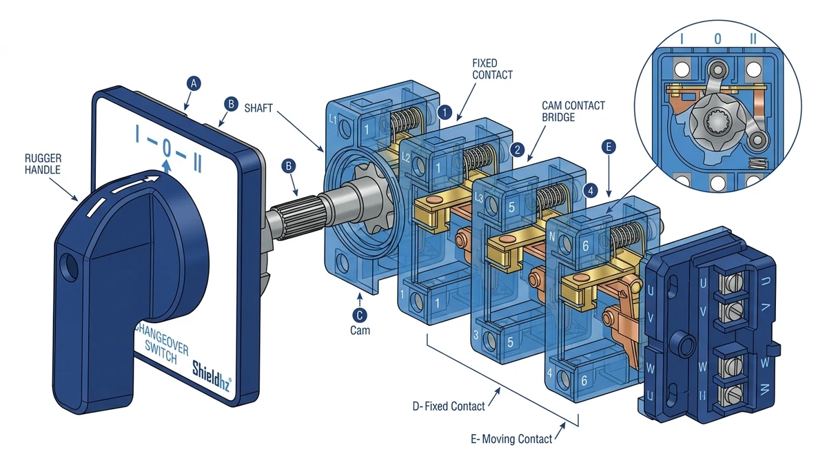
A changeover switch changes the connected circuit from one input to another. The most common form in low-voltage control and distribution panels is a manual rotary device with fixed positions. Internally, a cam mechanism opens and closes contact sets in a defined sequence as the handle turns.
For many panel builders, “changeover switch” means:
One load
Two possible sources or paths
One selected at a time
A deliberate OFF position in many designs
Mechanical switching logic that prevents overlap when specified as break-before-make
That makes the device useful where an operator or maintenance technician needs positive, visible manual source selection instead of automatic control.
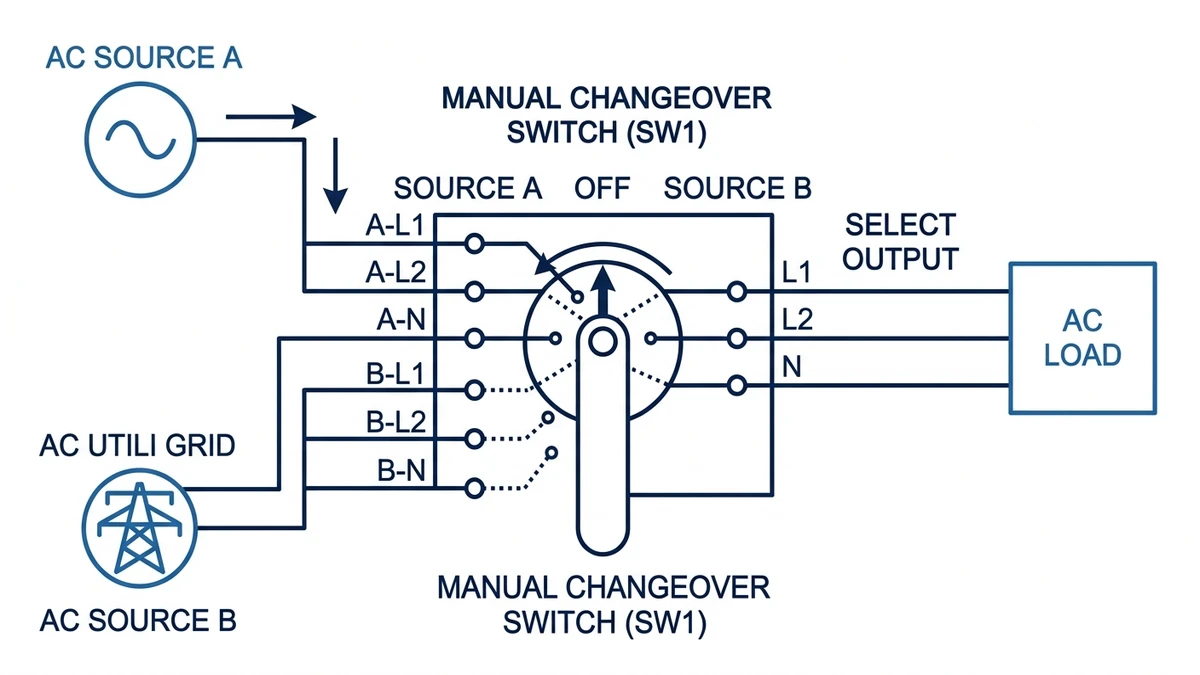
Basic changeover concept: one load, two sources, one selected path.
How manual source selection works
Manual source selection is exactly what it sounds like: a person turns the handle to choose which incoming circuit feeds the outgoing load. The switch does not sense utility loss, monitor voltage, or transfer by itself. It only changes state when operated.
A typical sequence is:
Position I: load connected to source 1
Position 0: load disconnected
Position II: load connected to source 2
This is the classic I-0-II arrangement. It is common in cam-operated assemblies because it gives the user a clear center-off state before selecting the alternate source. For maintenance teams, that center position can support lockout practice, testing, and reduced confusion during service work, depending on the overall panel design.
Understanding I-0-II logic
I-0-II is one of the most familiar handle markings for manual changeover duty.
I = first source or first circuit path
0 = OFF or isolated switching position
II = second source or second circuit path
The important point is not just the labeling. The internal contact diagram defines what happens at each position. Two switches may both say I-0-II on the front, yet have different pole arrangements, bridging logic, and current ratings.
For example, one changeover switch may be designed to switch:
2 poles for single-phase line and neutral
3 poles for three-phase lines
4 poles for three-phase plus neutral
Another may include extra auxiliary contacts for indication or interlock signaling. This is why handle marking alone is never enough for procurement.
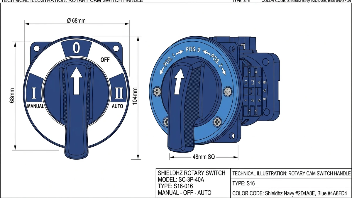
I-0-II handle marking shows source 1, OFF, and source 2.
Why break-before-make matters
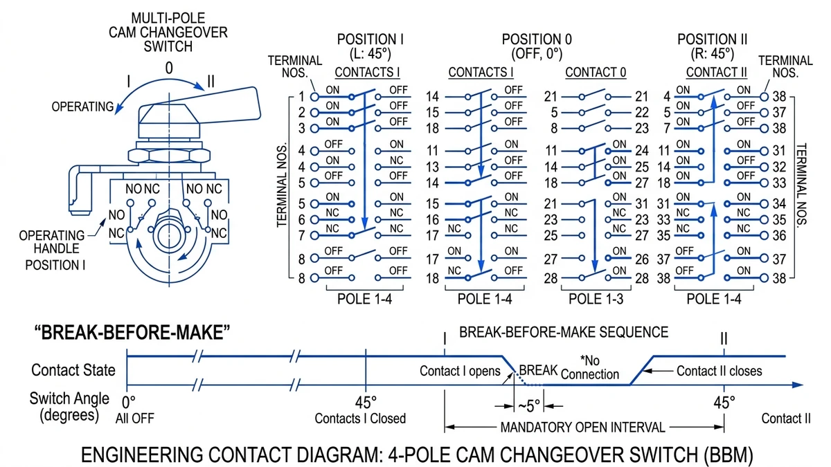
For source selection, break-before-make is often the safest and most important switching characteristic. It means the first circuit opens before the second circuit closes. In practical terms, the load is momentarily disconnected during transition, which helps avoid paralleling two sources through the switch.
This matters when the two sources must never be connected together, such as:
Utility and generator
Two independent feeders
Different transformer secondaries
Alternative machine supply paths
If a switch were make-before-break, the new source could connect before the old source disconnects. In a source-change application, that overlap may be unacceptable or dangerous unless the system is specifically engineered for it.
When reviewing a changeover switch, confirm the switching sequence in the contact chart or technical datasheet. Do not assume all rotary devices use the same transition logic.
Changeover switch vs transfer switch
These terms are sometimes mixed together, but they are not always identical in buyer discussions.
A manual changeover switch is generally a hand-operated device that selects one source or another. A transfer switch is a broader term that may include manual or automatic designs. In many facilities, “ATS” refers to an automatic transfer switch that senses source failure and transfers load according to programmed logic and interlocking.
Key differences:
Changeover switch:
Usually manual
Position-based operation
Often rotary cam or similar mechanism
Simpler control architecture
Transfer switch:
Can be manual or automatic
May include voltage sensing, delay timers, mechanical and electrical interlocks
Often selected for standby power systems
So, every manual source selector is not automatically equivalent to a full automatic transfer solution. If the application needs unattended switching after mains failure, a manual cam changeover switch is not a substitute for a properly engineered ATS package.
Changeover switch vs selector switch
A selector switch chooses a control function, but it does not always switch power paths. Many selector switches operate low-current control circuits for mode selection such as HAND-OFF-AUTO, LOCAL-REMOTE, or speed selection. A changeover switch, by contrast, often switches actual load or feeder conductors, depending on its rating and intended duty.
The two devices may look similar from the front because both can use rotary handles. The difference is in the electrical duty, pole structure, contact size, certification scope, and application intent.
If you are buying for a panel BOM, ask these questions:
Is this switching control signals or power conductors?
What is the operational current and utilization category?
Does the application require disconnection or switch-disconnector characteristics?
Is source overlap forbidden?
Is the neutral switched?
Those questions usually separate a light-duty selector device from a genuine changeover switching assembly.
Cam switch contact diagrams: how to read them
The contact diagram is the heart of a changeover switch specification. It tells you which contact pairs are closed in each handle position. For a cam switch, the internal cam profile controls that sequence.
Typical elements in a diagram include:
Numbered terminals
Pole groups
Position table
ON/OFF state by handle angle or marking
Sometimes a shorting or non-shorting notation
A simple 3-position source selector might show:
Position I: terminals for source 1 closed to load
Position 0: all source-to-load contacts open
Position II: terminals for source 2 closed to load
For three-phase applications, this logic is repeated across multiple poles. If neutral must also be transferred, a fourth pole may be included. Some applications require unswitched neutral instead, so the diagram must match the system philosophy.
The front handle marking is only the user interface. The actual engineering truth sits in the wiring diagram and contact schedule.
Contact diagrams define the real switching behavior behind the handle marking.
Standards and rating caution
For low-voltage switching devices, IEC frameworks matter, but only when the product is rated and documented for the intended duty. IEC 60947-3 is relevant to switches, disconnectors, switch-disconnectors, and fuse-combination units in low-voltage applications when the device is designed and tested for that service. Buyers should verify the exact product rating, utilization category, pole configuration, and documentation rather than assuming all rotary switches qualify the same way.
For OEM procurement teams, standards review should include:
Rated operational voltage
Rated operational current
Utilization category
Number of poles
Isolation or disconnector suitability if required
Short-circuit coordination expectations in the full assembly
Markings and certification documents for the specific model
This is especially important because a product family may include versions for different duties, while panel requirements stay fixed.
Where the LW28 route fits
Shieldhz manufactures rotary cam switch products and related control components from Zhejiang Province, China, with company operations established in 2014. The product line includes cam switches, isolator switches, push buttons, indicator lights, and terminal blocks. For buyers exploring source-selection hardware within that range, the main family route is the rotary cam switch category.
For documentation-heavy panel projects, the practical advantage is not only product range but repeatable engineering support. Zhejiang Shihe Electric Co., Ltd. operates a 5,000+ m2 manufacturing base with 100+ employees and 40+ production machines, and supports common industrial compliance documentation such as ISO9001, RoHS, CE, TUV, UL, UKCA, CCC, and CB where applicable to the specific product. Buyers should still request current documents for the exact model and rating, because approvals can vary by configuration.
Within that category, the LW28 series is the practical path to evaluate manual rotary source-selection configurations, depending on required poles, current ratings, mounting style, and contact logic. Product starting point: LW28 rotary cam switches.
That does not mean every application should default to one model. It means the buyer should map the application to:
Electrical duty
Position logic
Panel cutout and mounting method
Handle type
Front-plate legend
Required approvals and test documents
Wiring terminal style and conductor size
For engineering teams, the right route is not “find any I-0-II switch.” It is “find the exact contact program and rated duty.”
Common industrial applications
A manual changeover switch may be used in applications such as:
Selecting utility or generator supply for a local load
Choosing between redundant control transformers
Switching a motor circuit between alternate control paths where the design permits
Selecting normal or maintenance feed in a machine subpanel
Choosing one of two test sources in a service setup
Application boundaries still matter. Some source-transfer problems require interlocked contactors, motorized switching, or formal transfer equipment instead of a hand-operated cam switch. The panel designer should match the switch type to the risk profile and operating method.
Selection checklist for buyers and panel builders
Use this checklist before releasing a purchase order:
Confirm relevance of standards for the exact model and use case
Serviceability
Terminal access, labeling, spare strategy
Selection should match contact logic, poles, rating, and mounting details.
Frequent specification mistakes
The most common errors are basic, but costly:
Buying by handle label only
“I-0-II” does not confirm the internal contact program.
Ignoring break-before-make behavior
This can be a critical source-isolation issue.
Wrong pole count
Three-phase plus neutral often gets misread as 3P.
Assuming any selector switch can do power changeover
Control-duty and power-duty devices are not interchangeable.
Missing disconnector expectations
If isolation is part of the requirement, verify the exact product capability and markings.
Underchecking documentation
A clean datasheet package saves time during panel build, inspection, and replacement.
Forgetting handle and mounting details
Door-coupling parts, shaft kits, and front-plate legends matter in production.
Documentation buyers should request
To reduce approval delays, ask suppliers for a complete information set:
Product datasheet
Contact configuration chart
Dimensional drawing
Panel cutout details
Wiring diagram
Terminal capacity and torque data
Certificate list and declarations
Marking photo or label reference
Installation instructions
Part-number structure for options
This is also where supplier depth matters. Shieldhz positions its portfolio around industrial control components, including rotary cam switches and adjacent panel hardware, which helps buyers consolidate basic control-device sourcing without stretching part interpretation across unrelated catalogs.
When not to use a manual changeover switch
A manual changeover switch is not the right answer when you need:
Automatic transfer after source failure
Remote switching without operator presence
Closed-transition transfer engineered to avoid interruption
High fault-duty switching beyond the device’s intended rating
Complex interlocking across multiple system states
If the system risk is high or transfer logic is critical, the panel designer should escalate to a more specialized switching architecture.
Practical takeaway
If someone asks, “what is a changeover switch,” the shortest correct answer is this: it is a manual device that connects one load to one of two sources or circuit paths, usually through defined positions such as I-0-II. The engineering answer goes further – the right device depends on contact logic, break-before-make behavior, pole count, and verified duty ratings.
For buyers evaluating rotary source-selection hardware, start with the application logic, then the contact diagram, then the rating documents. If you need model guidance or documentation for a specific panel requirement, contact Shieldhz.
FAQ
What is a changeover switch used for?
A changeover switch is used to connect a load to one of two different power sources or circuit paths by manual operation. Typical examples include utility/generator selection or choosing between two incoming feeders.
Is a changeover switch the same as an automatic transfer switch?
No. A manual changeover switch requires an operator to move the handle. An automatic transfer switch monitors source conditions and transfers load through dedicated automatic control logic.
What does I-0-II mean on a changeover switch?
I-0-II means source 1, OFF, and source 2. The handle positions tell the operator which circuit path is selected, while the internal contact diagram defines the actual switching sequence.
Why is break-before-make important?
Break-before-make opens the first source before closing the second source. This helps prevent unintended overlap between two sources that should not be connected together.
Can a selector switch be used as a changeover switch?
Not always. Many selector switches are intended only for low-current control circuits. A true changeover switch must be checked for the required power-duty rating, contact arrangement, and source-selection logic.
How do I choose the right rotary changeover switch?
Check the pole count, I-0-II or other position logic, break-before-make behavior, current and voltage ratings, mounting style, and the exact contact diagram. Confirm documentation and certifications for the specific model before purchase.
Shi, Muxi
Shi, Muxi writes Shieldhz technical articles for industrial control and electrical component buyers, covering rotary cam switches, isolator switches, PV DC disconnects, push buttons, indicator lights, waterproof enclosures, and terminal blocks. The articles are based on Zhejiang Shihe Electric Co., Ltd.'s manufacturing and export experience, with practical emphasis on model selection, datasheets, drawings, certifications, IP ratings, and inquiry details buyers should confirm before ordering.