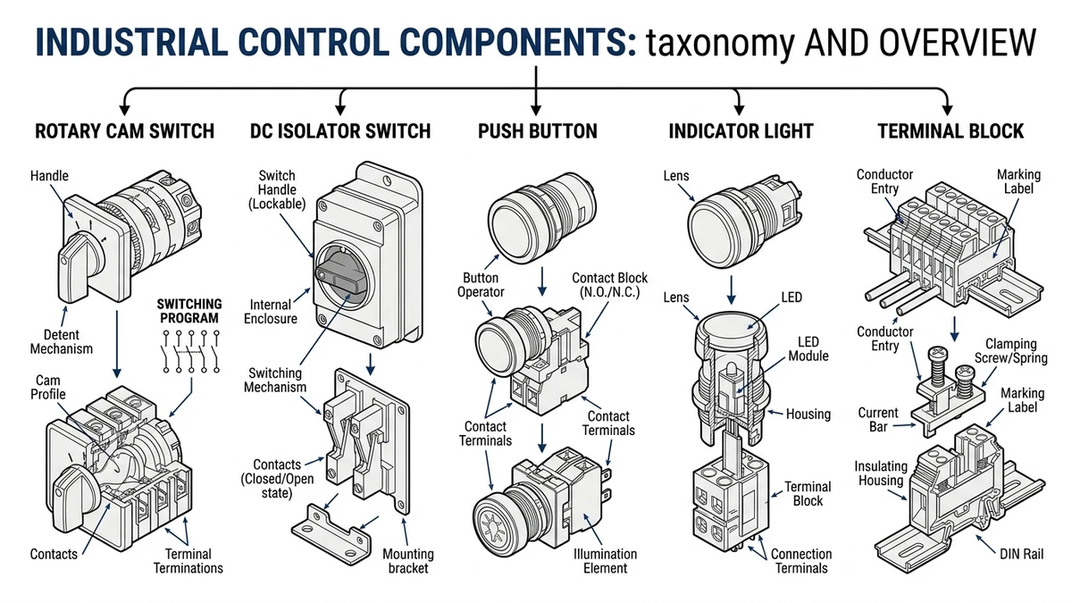
An industrial control component is a device used in industrial panels and machines to switch power, isolate equipment, route control signals, provide operator input, or indicate machine status. In simple terms, these are the building blocks that let a control panel work safely and predictably. Common examples include rotary cam switches, DC isolator switches, push buttons, panel indicator lights, and terminal blocks.
These parts are not interchangeable accessories. Each one is chosen for a specific electrical duty, operating environment, and user function. A component that appears suitable may still be the wrong choice if its utilization category, insulation level, IP rating, or contact design does not match the real application.
For engineers, panel builders, and maintenance teams, industrial control components generally serve three core purposes:
Switching — changing the path of current or selecting operating modes
Isolation — providing a safe disconnection point for servicing or fault response
Indication and interface — giving operators command inputs and visible feedback
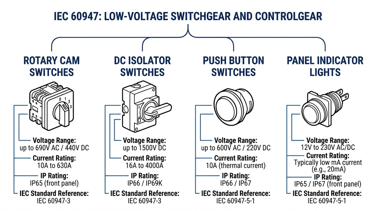
Across low-voltage industrial equipment, the IEC 60947 family is central to how many of these devices are classified and rated. For a broader overview of available device types, see the Shieldhz product overview.
Figure 1. Industrial control component categories compared by function, ratings, and IEC reference standards.
Core Categories of Industrial Control Components
Most industrial control components used in panels fall into a few main categories.
Switching components open, close, or redirect circuits. Rotary cam switches are a good example when one operator action needs to change multiple contacts in a defined sequence.
Isolation components disconnect equipment from its power source so downstream work can be carried out more safely. In both AC and DC systems, true isolators are selected according to voltage, current, duty, and the need for a verified open circuit.
Operator interface components include push buttons and indicator lights mounted on the panel face. They allow operators to send commands such as start, stop, or reset while showing conditions such as power on, running, or fault.
Wiring and connection components include terminal blocks, which organize internal and field wiring so circuits are easier to assemble, inspect, maintain, and expand.
In practice, these categories work together. A single control panel may use a selector switch for mode control, an isolator for lockable disconnection, push buttons and indicator lights for daily operation, and terminal blocks for structured cable termination.
Switching Components and Rotary Cam Switches
Switching devices control how current flows in a circuit. Some simply turn a circuit on or off. Others change over between sources, reverse a control scheme, or select a defined operating mode.
A rotary cam switch is especially useful when one shaft movement must create a repeatable contact pattern across multiple poles. Inside the device, rotating cam discs act on spring-loaded contacts. That mechanical arrangement determines which terminals are connected in each position. Because the switching logic is built into the cam design, the sequence is fixed and repeatable.
Typical uses include:
forward/off/reverse selection
line changeover
instrument selection
multi-position control
mode selection
When selecting a rotary switch, current rating alone is not enough. One of the most important checks is the utilization category under IEC 60947-3, which indicates the type of load the switch is designed to handle.
Common examples include:
AC-20A — switching with negligible load
AC-21A — resistive loads
AC-22A — mixed resistive and inductive loads
AC-23A — motor or highly inductive duties
For motor-related switching, AC-23A is often especially important because it reflects more demanding inductive conditions. Engineers should also verify the contact diagram, pole count, switching angle, number of positions, and endurance. Two switches can have similar headline ratings yet behave very differently if their switching sequences are not the same.
A switch and an isolator are not always the same thing. A standard switch may control a circuit during normal operation, but an isolator is intended to provide a recognized disconnection point for safe maintenance access.
A true isolator, or disconnector, is designed to create a defined separation between contacts in the off position. That distinction matters whenever technicians need to verify that downstream equipment is disconnected before servicing.
IEC 60947-3 covers low-voltage switches, disconnectors, switch-disconnectors, and related devices. During selection, engineers typically review:
rated insulation voltage
rated operational voltage
current rating
utilization category
making and breaking capability
suitability for isolation duty
Why DC Isolation Needs Special Attention
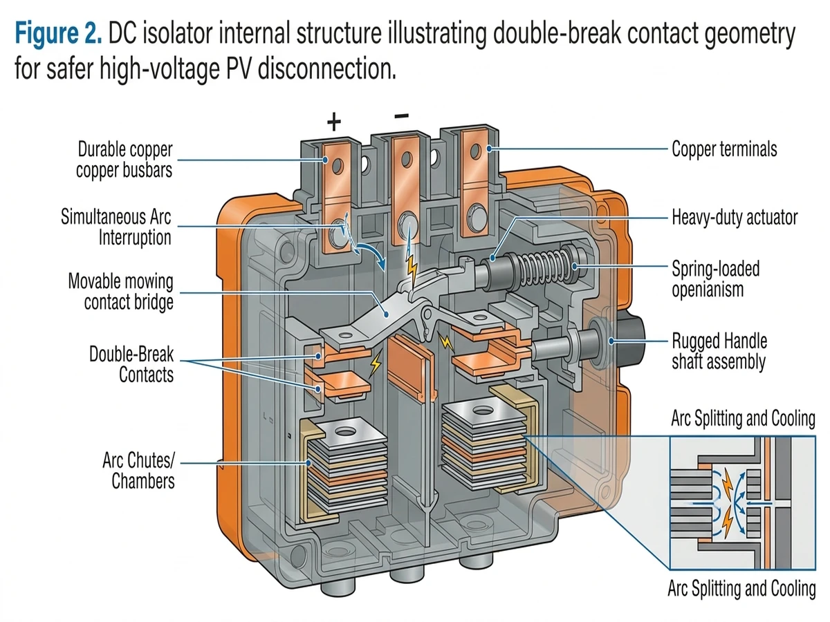
DC isolation deserves extra attention because direct current does not pass through a natural current zero in the way AC does. In AC systems, repeated zero crossings help arcs extinguish. In DC systems, once an arc forms, the device must interrupt it through contact separation and internal arc-control design.
That is why dedicated DC isolators are used where DC disconnection is required, especially in solar PV applications. DC isolator switches are intended for this duty, where voltage, current, and pole arrangement must match the actual system design.
Figure 2. DC isolator internal structure illustrating double-break contact geometry for safer high-voltage PV disconnection.
For DC isolator selection, review at least:
maximum DC voltage
number of poles and series configuration
operating current
panel-mount or enclosed format
IP rating where environmental exposure matters
standard compliance and published ratings
The practical takeaway is simple: if the application needs safe maintenance disconnection, choose a device specifically intended and rated for isolation rather than assuming any switch will do the same job.
Push Buttons and Indicator Lights
Push buttons and indicator lights form the panel’s most visible human-machine layer. They are usually control-circuit devices, not substitutes for main power switching.
IEC 60947-5-1 is the principal standard for many control-circuit devices and switching elements such as push buttons, selector switches, and pilot devices. These products are typically chosen according to control voltage, contact arrangement, mounting size, and environmental protection.
Common design considerations include:
momentary or maintained action
normally open and normally closed contacts
panel cut-out size
plastic or metal actuator construction
panel-face sealing
indicator lamp voltage and color
Color logic matters as well. IEC 60073 is widely used as a reference for actuator and indicator coding. In general:
Red indicates stop, emergency action, or fault
Green indicates normal or safe running condition
Yellow indicates caution or abnormal status
Blue indicates mandatory action
White or black may be used for general functions
Using these colors consistently helps reduce operator confusion. Examples of standard panel command devices can be found in the Shieldhz push buttons and indicator lights range.
Terminal Blocks and Wiring Distribution
Terminal blocks are the structured connection points that organize conductors inside a panel. They support field wiring, internal distribution, labeling, test access, and maintenance.
Although they receive less attention than switches or indicators, terminal blocks are critical to overall panel quality. Poor conductor termination can lead to intermittent faults, overheating, nuisance shutdowns, or time-consuming troubleshooting.
Two common types are screw-clamp terminal blocks and spring-clamp terminal blocks.
Screw-clamp designs use a screw mechanism to compress the conductor against a current bar or pressure plate. They remain common because they are familiar, flexible, and widely understood. Their performance depends on correct conductor preparation and proper tightening practice.
Spring-clamp designs use a spring mechanism to maintain contact force on the conductor. They are often chosen where vibration resistance or installation consistency is important. Even so, they still need to be matched correctly to conductor size and conductor type.
Typical causes of terminal connection problems include:
poor tightening practice
incorrect wire size
poor stripping length
contamination or corrosion
vibration
thermal cycling
As a practical rule, terminal blocks should be selected as part of the panel architecture, not added at the end of the design process. Voltage, current, mounting style, labeling, and accessory options all affect long-term serviceability.
IEC Standards Commonly Applied
Industrial control component selection should be based on the relevant standards, especially when comparing products with different functions or rating styles.
The IEC 60947 family is the main framework for low-voltage switchgear and controlgear. Frequently referenced parts include:
IEC 60947-1 — general rules
IEC 60947-3 — switches, disconnectors, and switch-disconnectors
IEC 60947-4-1 — contactors and motor starters
IEC 60947-5-1 — control-circuit devices and switching elements
IEC 60947-5-5 — emergency stop devices with mechanical latching function
These standards define how devices are rated and tested, including values such as rated insulation voltage, rated operational voltage, rated operational current, impulse withstand voltage, utilization category, and endurance.
For official standards references, use the IEC Webstore.
One common specification mistake is focusing only on current rating while ignoring utilization category. A device suitable for negligible-load switching may be unsuitable for motor duty even if the nominal ampere value appears acceptable.
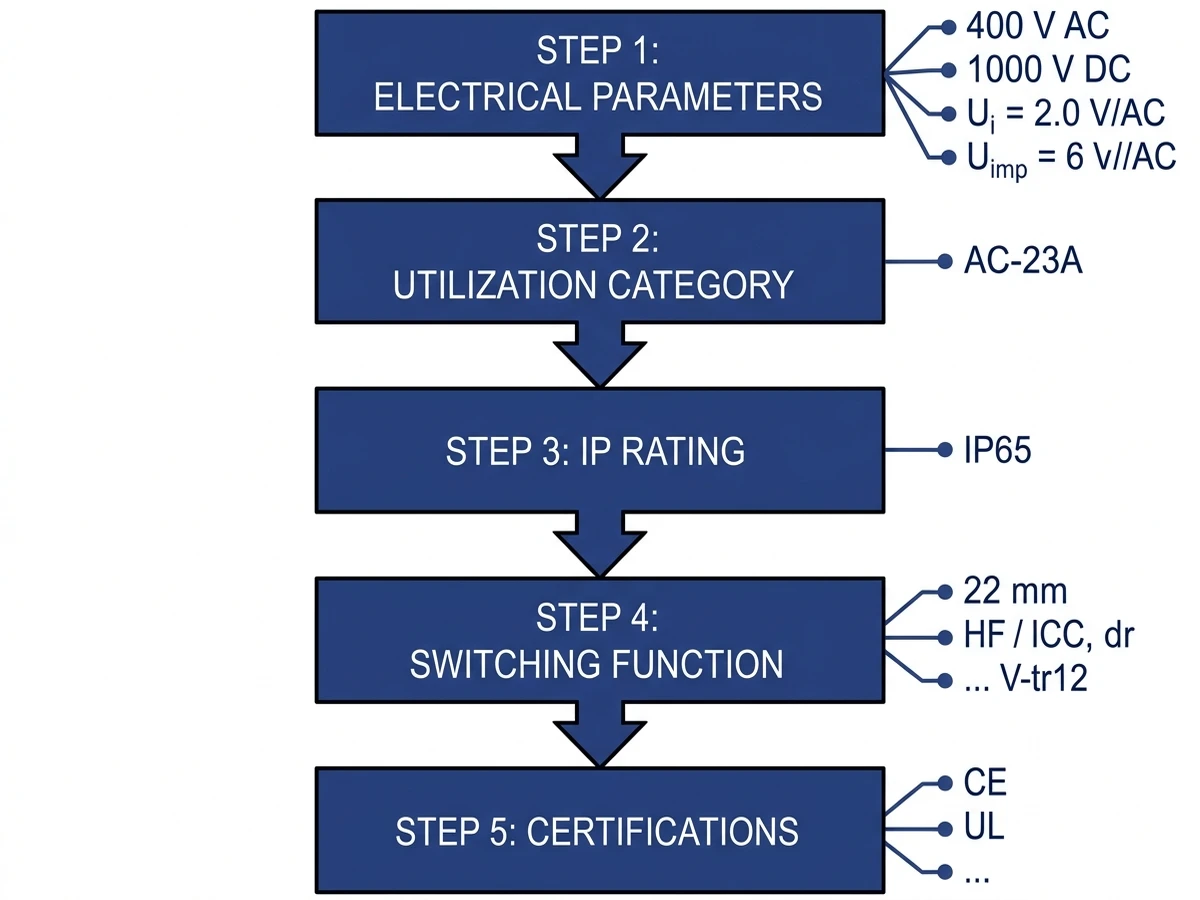
A Practical Selection Framework
Selecting the right industrial control component becomes easier when approached step by step.
Start with the electrical basics: determine whether the circuit is AC or DC, identify the operating voltage and current, and confirm whether the device will sit in a power circuit or a control circuit.
Next, match the component to the real duty. The utilization category should fit the actual load type rather than only the nominal numbers printed on the front page of a datasheet.
Then review environmental conditions. Dust, moisture, washdown exposure, outdoor installation, vibration, and temperature all influence enclosure choice, IP rating, and material selection.
After that, confirm the required function. The application may need:
simple on/off switching
certified isolation
multi-position selection
momentary command input
visual status indication
structured wiring termination
Finally, verify compliance and documentation. Datasheets, markings, wiring diagrams, and technical literature should be checked before final release. If details are unclear, request guidance through the Shieldhz contact page.
Where These Components Are Used
Industrial control components appear across a wide range of sectors because the same functional needs repeat in different kinds of equipment.
Typical applications include:
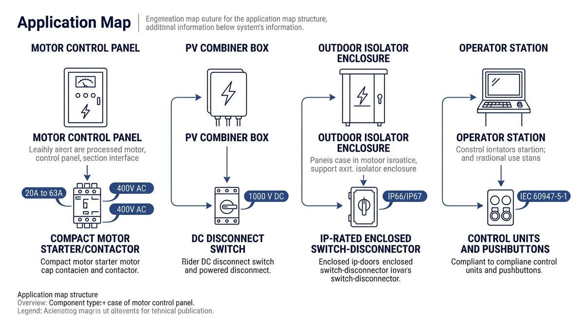
motor control panels using selector switches for mode or reversing functions
solar PV systems using DC isolators for equipment or string isolation
machine operator stations using push buttons and indicators
outdoor control points requiring enclosed disconnects and weather-resistant devices
general industrial panels using terminal blocks for structured field wiring
Figure 4. Application map connecting common industrial environments to appropriate control component types and ratings.
The exact product style changes with the environment and electrical duty, but the decision process stays largely the same: define the circuit, identify the function, apply the relevant standard, and verify that the device rating matches the real operating conditions.
Frequently Asked Questions
What is an industrial control component?
An industrial control component is a device used in industrial panels or machines to switch, isolate, indicate, or connect electrical circuits in a controlled and repeatable way.
What is the difference between a switch and an isolator?
A switch controls a circuit during operation, while an isolator is intended to provide a recognized safe disconnection point for maintenance, inspection, or servicing.
Why are DC isolator switches different from AC switches?
DC arcs are harder to extinguish because DC current does not naturally pass through zero. As a result, DC isolators rely more heavily on contact spacing and arc-control design.
Are push buttons used to switch main power?
Usually not. Most push buttons are control-circuit devices that send commands to relays, contactors, PLC inputs, or similar control elements rather than switching main power directly.
Why does the utilization category matter?
The utilization category indicates the type of electrical duty a device can handle. A switch suitable for negligible load may not be suitable for motor or inductive switching.
What causes terminal block connection problems?
Common causes include poor tightening practice, wrong conductor size, vibration, thermal cycling, contamination, and improper stripping length.
Shi, Muxi
Shi, Muxi writes Shieldhz technical articles for industrial control and electrical component buyers, covering rotary cam switches, isolator switches, PV DC disconnects, push buttons, indicator lights, waterproof enclosures, and terminal blocks. The articles are based on Zhejiang Shihe Electric Co., Ltd.'s manufacturing and export experience, with practical emphasis on model selection, datasheets, drawings, certifications, IP ratings, and inquiry details buyers should confirm before ordering.