What Is an Isolator Switch? Definition and Core Function
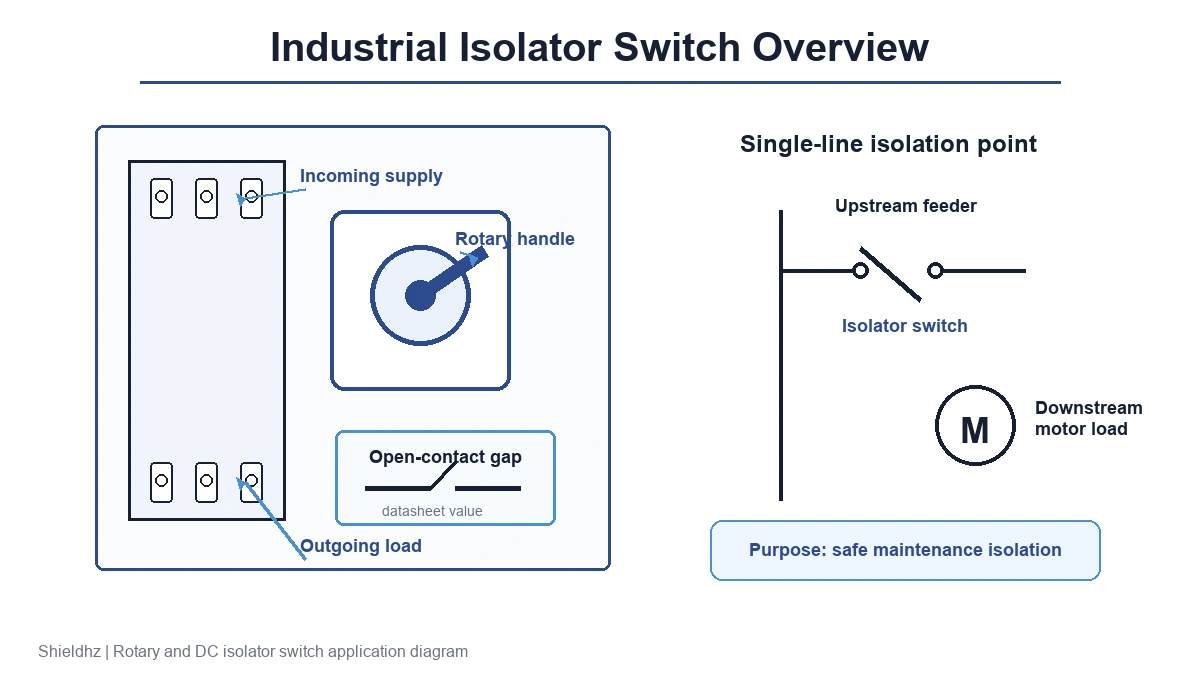
An isolator switch is a manually operated disconnect device that creates a visible, verifiable open gap in a circuit, ensuring no voltage reaches downstream equipment during maintenance or inspection. Unlike a circuit breaker, an isolator switch is not designed to interrupt fault currents — its sole function is to establish a safe, de-energized working condition.
How an Isolator Switch Creates Circuit Isolation
Under IEC 60947-3 — the standard governing disconnectors, isolators, and switch-disconnectors — an isolating device must provide open-contact separation and dielectric performance suitable for its rated insulation voltage and impulse withstand voltage. The exact clearance distance is model- and rating-dependent, so it should be confirmed from the device datasheet and certification file rather than assumed from a generic number. The practical point is simple: the open contact gap gives maintenance teams a physical isolation state, not just a switched-off indication.
In a typical industrial control panel, an isolator switch is positioned at the incoming feeder line so service personnel can establish a defined off-state before opening the enclosure. That visible OFF position also supports lockout/tagout (LOTO) workflows when the handle or shaft can be physically locked.
Core Functional Distinction from Other Switching Devices
An isolator switch carries rated current continuously, but a plain isolator is not a substitute for an overcurrent protective device. Where the device is also rated as a switch-disconnector or load-break switch, the manufacturer must state the applicable utilization category and making/breaking duty. For example, a rotary-type isolator is selected first for its rated current, voltage, pole count, and contact separation; fault interruption still belongs to a coordinated protective device upstream.
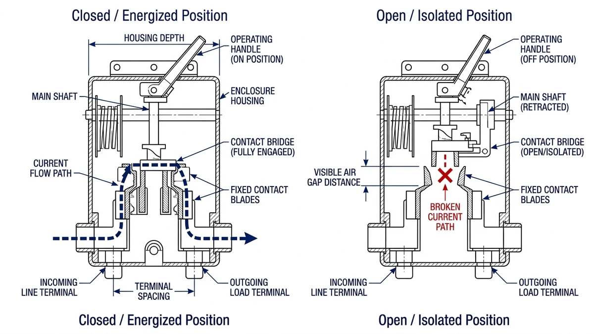
Figure 1. Side-by-side cross-section of an isolator switch in closed (energized) and open (isolated) states, showing the datasheet-defined open-contact gap used to establish a physical isolation state.
How Does an Isolator Switch Work? Switching Mechanics Explained
Contact Separation and the Air-Gap Principle
When an isolator switch opens, the moving contact travels to a manufacturer-defined open position that satisfies the device’s rated insulation and impulse withstand requirements. The required distance and test voltage vary by voltage class, pole construction, and certification route. For selection work, treat the open-gap value as a datasheet parameter, then confirm that the selected device is certified for the system voltage and installation category.
In an industrial maintenance scenario, this visible open-gap state allows service personnel to confirm de-energization by direct inspection — an important safety step before opening a control panel or working on downstream equipment.
Arc Management During Switching
Even when isolating a de-energized or near-zero-load circuit, residual inductance can create a transient arc at contact separation. Devices that are also certified for making and breaking duty under categories such as AC-23A use contact geometry and arc-control features appropriate to that duty. Contact material, mechanical endurance, and electrical endurance are all model-specific values; they should be checked on the datasheet before a device is assigned to a switching task rather than an isolation-only task.
For maintenance checks, compare closed-contact resistance and temperature rise against the manufacturer’s test limits. A rising trend is more useful than a generic absolute value because contact design, rating, and measurement method all affect the expected reading.
For DC circuits — where arcs are harder to quench than in AC systems — purpose-rated DC isolator switches use contact arrangements and arc-control features designed for direct current service. Full technical requirements for disconnectors and isolators are defined in IEC 60947-3, so the selected DC model should be checked against its rated DC voltage, current, pole configuration, and declared utilization category. This is especially important in photovoltaic and battery storage applications where arc extinction cannot rely on a natural current zero-crossing.
[Expert Insight] — Maintenance Checks
– Inspect contact surfaces for pitting or discoloration at every scheduled maintenance interval; early erosion is a leading indicator of impending contact weld failure, not simply cosmetic wear.
– On DC circuits, never substitute an AC-rated isolator even temporarily — a single high-energy switching event can weld contacts permanently closed, eliminating the isolation function entirely.
– When replacing contact blocks, handles, shafts, or enclosure parts, use the manufacturer’s matched spare parts instead of mixing components from visually similar switch families.
– After any suspected overload or energized switching event, perform a contact resistance and temperature-rise check against the datasheet before returning the isolator to service.
Types of Isolator Switches: A Practical Classification Guide
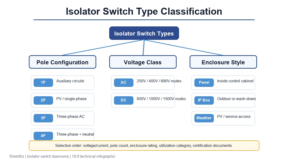
IEC 60947-3 defines performance requirements across four key axes: rated insulation voltage (Ui), rated current, pole count, and utilization category. Within that framework, the practical classification most engineers use groups isolator switches by pole configuration first, then voltage class, then environmental rating.
Figure 2. Classification taxonomy of isolator switch types branching from pole configuration (1P–4P) through AC/DC voltage class to enclosure IP rating, with representative current ranges and application contexts at each terminal node.
Type
Pole Config
Voltage Class
Typical Application
Example Format
Single-pole isolator
1P
Up to 440V AC
Auxiliary circuits, lighting branch
Panel-mount rotary
Double-pole isolator
2P
Up to 1,000V DC
PV string disconnection
DC isolator switch
Triple-pole isolator
3P
Up to 690V AC
Three-phase motor feeders
Rotary cam, DIN-rail
Four-pole isolator
4P
Up to 690V AC
Three-phase + neutral (TN-S systems)
Rotary cam switch
Weatherproof isolator
2P / 3P
Up to 500V AC
Outdoor plant, marine, agriculture
IP65–IP66 enclosure box
PV DC isolator
2P / 4P
Up to 1,500V DC
Solar rooftop, utility strings
GF40 PV DC isolator
How Voltage Class Drives Selection
Voltage class is one of the first filters, but it should not be treated as a single universal boundary. For AC systems, check rated operational voltage, rated insulation voltage, utilization category, and pole count together. For DC circuits — particularly photovoltaic installations — the design voltage must account for maximum open-circuit string voltage under cold-temperature conditions, which can push working voltage above the nominal array rating. A DC isolator should be selected above the calculated maximum Voc with a margin defined by the project standard, local code, and manufacturer data.
For PV circuits, calculate Voc,max from the module datasheet and the lowest expected site temperature before selecting a DC isolator. Do not size the switch from nominal array voltage alone.
For weatherproof applications, enclosure ingress protection — rated IP54 to IP66 under IEC 60529 — is an independent selection criterion layered on top of pole count and voltage class.
Key Selection Criteria: How to Choose the Right Isolator Switch
Priority 1 — Voltage and Current Ratings
Select rated insulation voltage (Ui) and rated operational voltage (Ue) above the actual system voltage, then confirm rated current, short-circuit coordination, and utilization category from the datasheet. For solar string circuits, size current from the module short-circuit current and the safety factors required by the project standard or local code.
Priority 2 — Pole Configuration
Pole selection must match the earthing system, wiring diagram, and local isolation rules. Many PV strings use 2-pole or 4-pole DC isolation so all required conductors open together; three-phase AC circuits typically use 3-pole or 4-pole devices depending on whether neutral isolation is required. Do not infer pole count from phase count alone.
Priority 3 — Enclosure and IP Rating
Outdoor or wash-down environments commonly start at IP65, while temporary immersion or harsh exposure may require a higher rating if the application calls for it. For rooftop solar installations, an IP65-rated enclosure such as the SHP waterproof isolator switch is a widely adopted baseline, while indoor panel isolators often use lower enclosure ratings where the panel itself provides protection.
Priority 4 — Switching Duty and Load Type
Resistive loads place far less arc stress on contacts than inductive motor loads. If the device will only be used for off-load isolation, confirm the disconnector rating and upstream protective coordination. If it must make or break energized motor current, specify a switch-disconnector or load-break device with the correct utilization category, such as AC-23A where applicable.
Priority 5 — Standards Compliance and Certifications
Verify CE marking and, for DC photovoltaic circuits, compliance with IEC 60947-3 and local grid-connection codes. For installations following UL standards, confirm UL 508 listing. The GF40 PV DC isolator switch and related DC-rated products are designed around these certification requirements for solar applications.
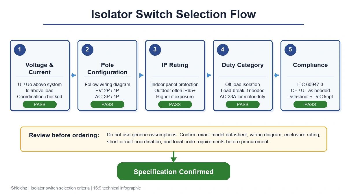
Figure 3. Five-stage selection flowchart for isolator switch specification, progressing from voltage and current rating through pole configuration, IP enclosure rating, utilization category, and certification compliance — with pass and review branches at each decision node.
[Expert Insight] — Specifying Isolators Without Common Pitfalls
– Always calculate maximum open-circuit string voltage at the lowest expected ambient temperature, not only at standard test conditions, because cold-temperature Voc can move a borderline PV isolator outside its safe rating.
– When specifying for motor circuits, request the manufacturer’s utilization-category data for the exact current and voltage combination, since resistive-load and inductive-load ratings are not interchangeable.
– For panels subject to third-party inspection, keep the isolator declaration of conformity and datasheet with the circuit schedule so the device-level rating can be checked quickly.
– If a project spans multiple countries, confirm whether local grid codes add requirements beyond IEC 60947-3, especially for pole count, enclosure rating, and lockable isolation.
Where Are Isolator Switches Used? Industrial, Solar, and Residential Applications
Industrial Motor Control and Panel Applications
In industrial environments, isolator switches are typically positioned at the incoming feeder of motor control panels, allowing maintenance teams to establish a defined de-energized state before opening an enclosure. A common arrangement places an appropriately rated rotary cam isolator upstream of each motor starter, satisfying the disconnection function requirements of IEC 60947-3 for low-voltage switchgear. Clear ON/OFF markings, padlockable handles, and consistent panel labeling reduce ambiguity during switchgear servicing. For panels requiring multi-position or source-changeover isolation, the LW28 rotary cam switch series provides a compact, IEC-rated option.
Solar PV DC Isolation
Photovoltaic systems introduce a specific isolation challenge: DC circuits do not have a natural current zero-crossing, making arc interruption more demanding than in AC systems. For rooftop PV strings, a DC isolator is selected around the maximum open-circuit voltage of the array, string short-circuit current, pole count, and the ingress protection rating required by the installation environment. The GF40 PV DC isolator switch is purpose-rated for these DC PV conditions, where a standard AC-only isolator would not be an acceptable substitute.
Residential and Outdoor Installations
In residential applications, isolator switches appear at sub-boards, air-conditioning circuits, and pool or garden equipment supplies. Outdoor installations commonly specify IP65 or higher under IEC 60529-based enclosure ratings to reduce water and dust ingress in exposed conditions. A weatherproof isolator switch in a sealed housing addresses this requirement, with some designs also offering padlocking provisions to enforce lockout/tagout safety procedures during equipment servicing.
Common Mistakes When Installing or Selecting Isolator Switches
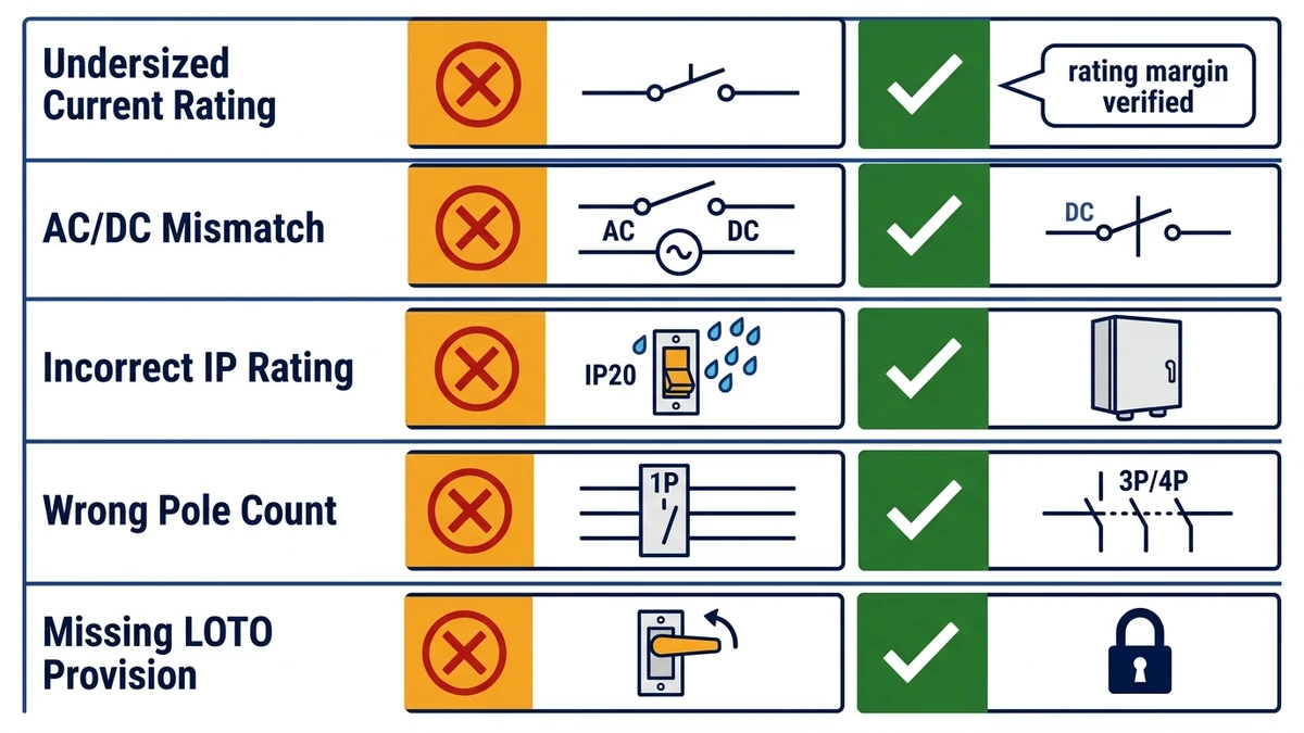
Figure 4. Diagnostic checklist of five common isolator switch specification and installation errors — undersized rating, AC/DC mismatch, incorrect IP rating, wrong pole count, and missing LOTO provision — with corrective actions for each.
Mistake 1: Undersizing the Current Rating
Selecting an isolator switch rated below the circuit’s full-load current causes contact resistance to rise under continuous thermal stress, accelerating oxidation and eventual failure.
Corrective guidance: Apply the margin required by the project standard and the manufacturer’s datasheet, then check temperature rise and short-circuit coordination. For continuous-duty circuits, avoid selecting a switch exactly at the calculated load current.
Mistake 2: Ignoring Voltage Type — AC vs. DC
Installing an AC-rated isolator on a DC circuit is a critical mismatch. DC arcs do not pass through a natural zero-crossing, making them significantly harder to extinguish. Standard AC isolators are not designed for DC arc interruption and may fail to break the circuit safely.
Corrective guidance: For photovoltaic or battery systems, use a purpose-built DC isolator switch rated for the maximum open-circuit string voltage, typically 600 V DC to 1,500 V DC in commercial PV applications.
Mistake 3: Incorrect Ingress Protection Rating for the Environment
Mounting an IP20-rated switch in an outdoor or wet-area location exposes live components to moisture ingress, leading to insulation degradation and potential arc-flash events.
Corrective guidance: Match the enclosure IP rating to the installation environment. Outdoor and washdown locations commonly start at IP65 under IEC 60529-based ratings, with higher ratings selected where exposure is more severe.
Mistake 4: Misidentifying the Required Pole Count
Using a single-pole isolator on a three-phase circuit leaves two live conductors energized during isolation, which defeats the purpose of safe isolation and creates a serious maintenance hazard.
Corrective guidance: Three-phase circuits require a 3-pole or 4-pole isolator switch to simultaneously disconnect all live conductors.
Mistake 5: Omitting Mechanical Lockout Capability
Isolators without a lockout-tagout (LOTO) provision cannot be locked in the OFF position, creating a hazardous exposure risk during maintenance.
Corrective guidance: Specify switches with a padlock-compatible handle or shaft. Confirm LOTO-compatible actuator options before procurement.
Shieldhz Isolator Switches: Engineered for Reliable Circuit Isolation
AC and DC Isolation Solutions
For three-phase industrial circuits, the LW28 and LW42 rotary cam switch series cover a broad range of rotary isolation, selector, and changeover duties for control panels, with cam-actuated contact mechanisms built around IEC 60947-3 disconnector requirements. For photovoltaic systems, the GF40 and GF51 PV DC isolator switch routes cover DC string isolation across model-specific voltage and pole configurations, addressing the elevated arc-control demands that DC service imposes.
Weatherproof and Enclosed Configurations
In outdoor or wash-down environments, enclosure ingress protection is a primary selection criterion. The SHP and SH30 weatherproof isolator switch range provides enclosed housing options for rooftop mounting, outdoor equipment, and industrial machinery with water or dust exposure; confirm the exact IP rating on the selected model.
Certifications and Quality Assurance
Shieldhz operates from a 5,000+ m² manufacturing facility in Zhejiang Province, with 40+ dedicated production machines and in-house quality testing aligned to IEC certification requirements. Products carry CE marking and are tested to rated insulation voltage parameters before shipment.
Whether you are specifying an AC rotary isolator, a solar DC disconnect, or a weatherproof enclosed switch, the Shieldhz product catalog covers the utilization categories and enclosure ratings your application demands. For a specific model route, contact the Shieldhz technical team to discuss specification requirements directly.
Frequently Asked Questions
What is the difference between an isolator switch and a circuit breaker?
A circuit breaker is rated to interrupt fault currents and can trip automatically under overload or short-circuit conditions, whereas an isolator switch is a manually operated device whose only function is to create a verified open gap for safe maintenance access. Isolator switches carry continuous rated current but are not designed or tested for fault breaking duty.
Can an isolator switch be used to turn equipment on and off during normal operation?
Isolator switches are not intended for routine switching of load current unless the exact device is also rated as a switch-disconnector for that duty. In normal isolation practice, the load is switched off by another device first, then the isolator establishes the de-energized state.
Why do solar PV systems require a DC-specific isolator switch?
Direct current arcs do not self-extinguish at a natural current zero-crossing the way AC arcs do, so a standard AC-only isolator is not suitable for PV DC service. A purpose-rated DC isolator uses contact geometry and arc-control features tested for its declared DC voltage, current, and pole configuration.
What IP rating does an outdoor isolator switch need?
IP65 is a common starting point for exposed outdoor isolator switches because it covers dust-tight construction and water-jet resistance under IEC 60529. Locations with a realistic risk of temporary immersion or heavy washdown should be checked against a higher-rated enclosure and the manufacturer’s installation instructions.
How many poles does an isolator switch need for a three-phase circuit?
A three-phase circuit normally requires a 3-pole isolator to disconnect all three live conductors. Where the neutral must also be isolated, a 4-pole device may be required by the wiring system or local code. Using a single-pole or double-pole isolator on a three-phase supply can leave conductors energized during maintenance.
What does utilization category AC-23A mean on an isolator switch?
AC-23A is an IEC 60947-3 classification indicating the switch has been tested and rated for making and breaking currents associated with motor and other inductive loads, which produce higher arc energy than resistive loads at the same current. Specifying a switch with the correct utilization category for the actual load type prevents premature contact erosion and ensures the device performs within its tested safety envelope.
Is a lockout-tagout (LOTO) provision required on an isolator switch?
Many industrial safety programs and site-level LOTO procedures require isolation points to be physically lockable in the OFF position to prevent accidental re-energization during maintenance. Even where the device standard is not the only source of this requirement, a padlock-compatible handle is a practical necessity for most industrial and commercial panel installations.
Shi, Muxi
Shi, Muxi writes Shieldhz technical articles for industrial control and electrical component buyers, covering rotary cam switches, isolator switches, PV DC disconnects, push buttons, indicator lights, waterproof enclosures, and terminal blocks. The articles are based on Zhejiang Shihe Electric Co., Ltd.'s manufacturing and export experience, with practical emphasis on model selection, datasheets, drawings, certifications, IP ratings, and inquiry details buyers should confirm before ordering.