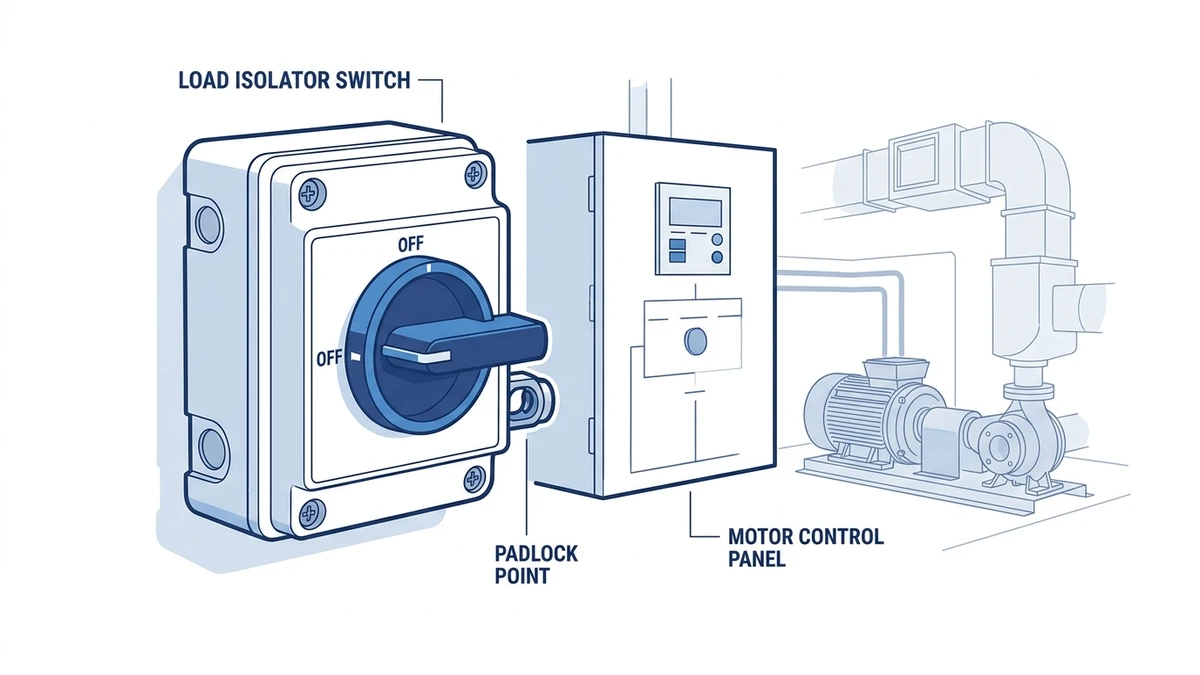
A load isolator switch is a manually operated disconnect device that creates a verifiable, electrically safe open gap between a power source and a load – such as a motor, HVAC unit, or pump. Rated typically from 16 A to 125 A at up to 690 V AC, it enables local isolation so maintenance personnel can de-energize equipment safely at the point of use.
How a Load Isolator Switch Works
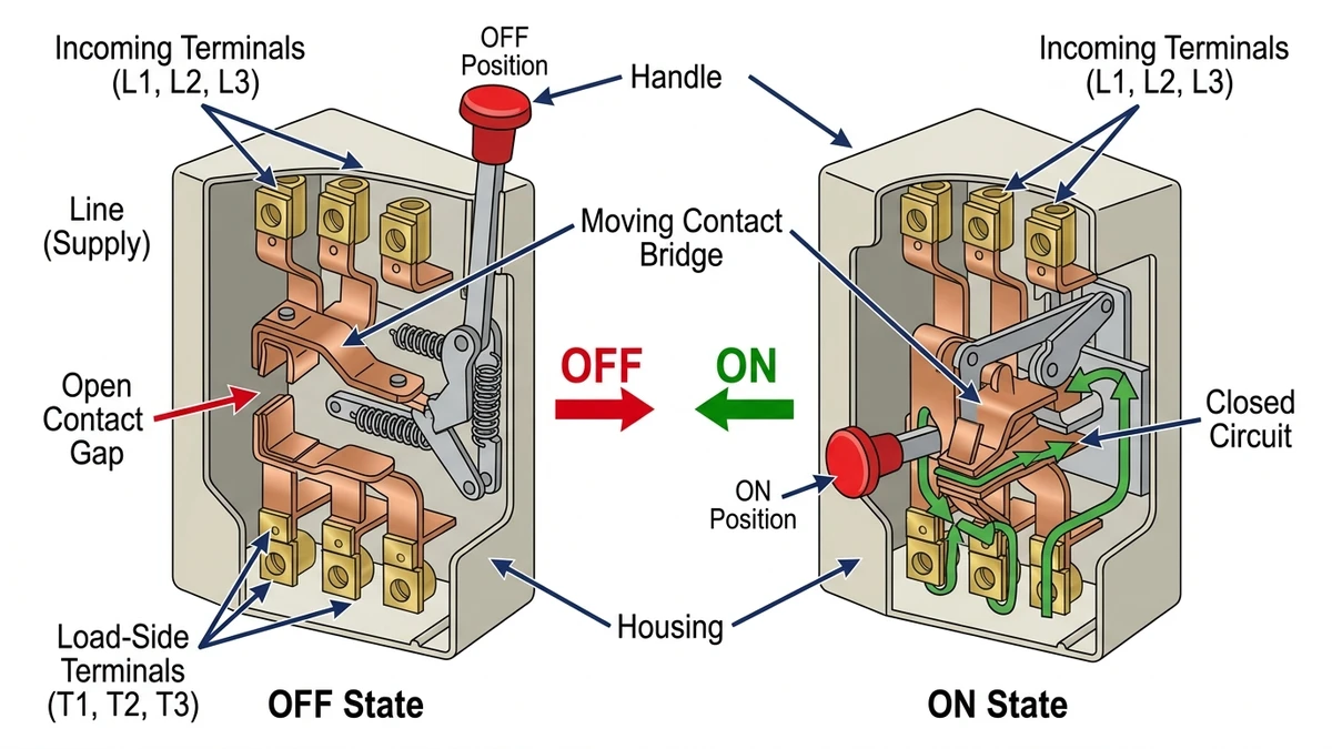
When the operator rotates or pulls the actuator to the OFF position, the switch opens the selected poles through a multi-pole mechanism. The exact isolating function must be verified against the product documentation and the relevant IEC 60947-3 rating for the model being specified.
In a typical industrial motor control scenario, a load isolator switch is placed close enough to the motor starter or drive enclosure that the service technician has a clear, lockable OFF position at the point of work. Exact placement should follow the local wiring code, machine safety standard, and project risk assessment.
Why “Load-Break” Capability Matters
Unlike a simple isolator that must only be operated under no-load conditions, a load isolator switch carries a defined making and breaking capacity – typically expressed as utilization category AC-23A for motor loads. This means the device can interrupt the inductive current of a running motor without destructive arcing, a critical distinction for HVAC compressors and pump motors that may not be pre-stopped before local isolation is needed.
For guidance on rotary cam switches commonly used as load isolators in motor and HVAC panels, or to explore the full Shieldhz product range, both pages provide current ratings, pole configurations, and enclosure options.
The internal contact gap and switching mechanism should match the declared isolation rating for the exact model.
How a Load Isolator Switch Works: Switching Mechanics and Isolation Principles
Understanding the internal mechanics separates informed product selection from guesswork – what happens inside the switch body directly determines whether isolation is genuine or merely assumed.
Contact Separation Mechanics
The core isolation event depends on the distance achieved between the moving and stationary contacts when the switch reaches its fully open position. In cam-type isolator switches – such as those designed to IEC 60947-3, the International Electrotechnical Commission standard for disconnectors and switch-disconnectors – the contact gap must match the rated insulation and impulse-withstand data declared for the exact switch. Contact materials, terminal design, and arc-control geometry should be checked in the datasheet rather than assumed from the front handle style.
The Visible Isolation Gap Principle
A clear OFF state is not incidental; it is one of the practical reasons buyers specify a load isolator instead of relying on a contactor or a basic control switch. When the handle rotates to OFF, the mechanism should provide a declared, lockable state that the maintenance procedure can rely on. Rotary cam isolators, including those in the LW28 series and SH30 series, use defined cam positions to support repeatable ON/OFF operation.
Arc Interruption During Switching
When contacts separate under load, the collapsing magnetic field in an inductive motor or HVAC compressor circuit can drive current to continue flowing as an arc. For those applications, confirm whether the model is rated for the required IEC 60947-3 utilization category, such as AC-23A where applicable.
[Expert Insight] – Field Tips: Verifying True Isolation
– Never rely solely on handle position to confirm isolation; always follow up with a calibrated voltmeter at the load terminals before touching any conductors.
– If the switch sees frequent operation, include contact condition and terminal heating in periodic maintenance checks.
– If the actuator feels spongy or fails to click decisively into the OFF detent, the cam mechanism may be worn; replace the switch rather than continuing to use it as a safety barrier.
– On rotary cam designs, confirm the angular travel physically reaches 0 degrees (OFF) – partial rotation can leave contacts bridged even when the handle appears off.
Load Isolator Switch Types: Rotary, Toggle, and Modular Formats
With the operating principles established, the practical question becomes which physical format best suits a given installation – and the answer turns on current rating, panel geometry, and environmental exposure.
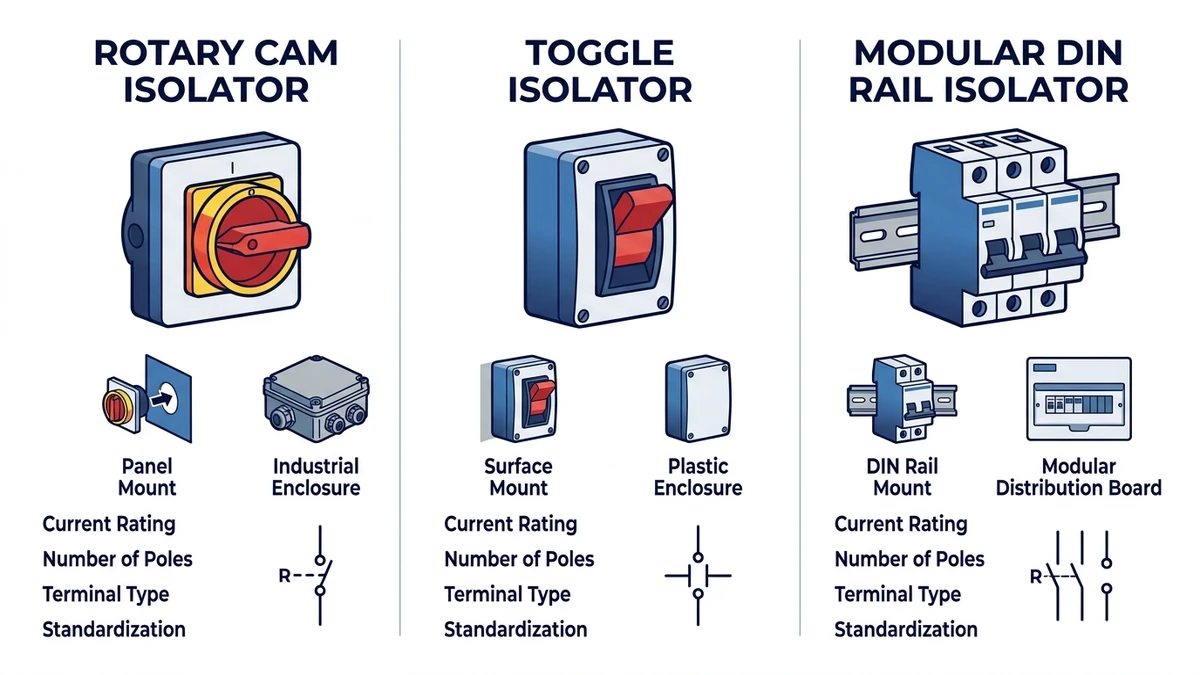
Rotary Format
Rotary isolator switches use a cam-actuated mechanism that rotates through defined angular positions, typically 0 degrees (OFF) and 90 degrees (ON), to open or close all poles simultaneously. This format supports current ratings from 16 A to 125 A and above, making it the preferred choice for motor isolation, HVAC disconnect, and pump control panels. The multi-position cam design also enables selector functions, giving engineers flexibility in control circuit layout. Rotary cam switches in the LW28 and LW42 series are representative of this format, offering panel-mount and DIN rail options with IP65-rated enclosures available for outdoor service.
Toggle Format
Toggle isolator switches use a lever or handle mechanism and are typically limited to lower current ratings – generally up to 32 A at 400 V AC – in residential and light commercial applications. Their compact footprint suits space-constrained enclosures, though they generally provide less tactile feedback for confirmed OFF-state verification compared to rotary formats.
Modular Format
Modular isolators integrate into DIN rail systems alongside MCBs and contactors, enabling standardized panel assembly. Current ratings typically range from 20 A to 100 A per pole, and modular formats support plug-in auxiliary contacts for remote indication.
Format Comparison by Key Parameters
Parameter
Rotary
Toggle
Modular
Typical Current Range
16 A-125 A+
up to 32 A
20 A-100 A
Mounting
Panel cutout / surface
Panel cutout
35 mm DIN rail
Pole Configurations
1P, 2P, 3P, 4P
1P, 2P
1P, 2P, 3P, 4P
Enclosure Rating
Up to IP67 (boxed)
Up to IP55
IP20 (open panel)
Typical Application
Motors, HVAC, pumps
Light machinery
Distribution boards
IEC Utilization Category
AC-23A, AC-22A
AC-21A, AC-22A
AC-21A, AC-22A
For installations exposed to moisture, dust, or mechanical impact – such as rooftop HVAC units or pump rooms – weatherproof isolator switch enclosures housing rotary mechanisms provide the most robust combination of high current handling and environmental protection.
Load isolator switch format selection depends on rating, mounting method, pole count, and environment.
Load Isolator Switch Applications: Motors, HVAC Units, and Pumps
Format selection feeds directly into application selection – and each load type places distinct electrical demands on the isolator that must be addressed at the specification stage.
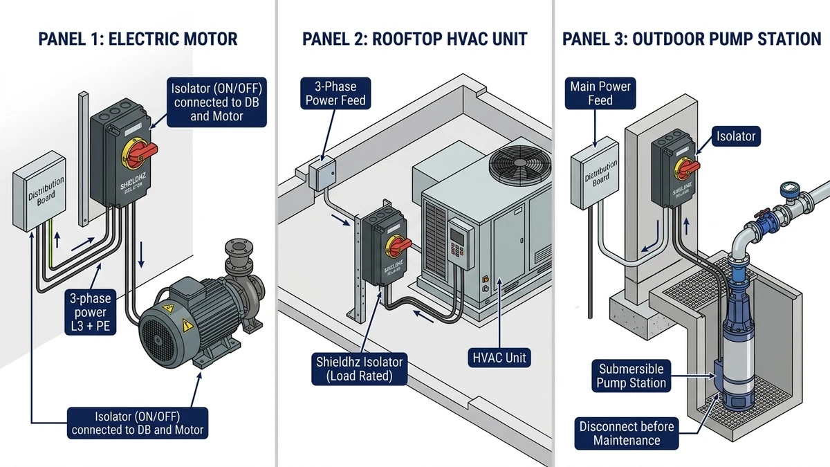
Electric Motor Isolation
Motors present one of the more demanding isolation scenarios because inrush and stopping conditions vary by load. A load isolator installed at a motor disconnect point should be checked against motor full-load current, enclosure derating, pole count, and the intended IEC 60947-3 utilization category. Rotary cam switch designs – such as the LW28 series – are commonly evaluated in motor control panels because their contact architecture can support defined switching programs alongside isolation.
HVAC Unit Isolation
Rooftop and plant-room HVAC units often need enclosed isolators selected for semi-exposed or outdoor service. IP65 is a common starting point, while direct spray, coastal exposure, or washdown conditions may call for a higher enclosure rating. A weatherproof isolator switch mounted at the unit can give service teams a clearer local isolation point without returning to a remote distribution board.
Pump Isolation
In pumping applications – particularly water treatment, irrigation, and building services – the isolator is typically installed adjacent to the pump motor in conditions involving moisture, condensation, or chemical splash. Submersible pump circuits additionally require isolators capable of interrupting capacitor-start loads. For outdoor pump stations, a waterproof isolator box rated to IP66 or IP67 with UV-stabilized housing materials provides reliable local isolation across seasonal temperature ranges from -25 degreesC to +60 degreesC.
[Expert Insight] – Field Tips: Application-Specific Commissioning
– For motor applications, record the isolator’s rated operational current (Ie) against the motor nameplate FLA at commissioning, and flag any mismatch for engineering review before service.
– On rooftop HVAC installations, seal all cable entry glands to the same IP class as the enclosure – an IP65 isolator fitted with an IP54 gland is effectively an IP54 assembly in a rain event.
– In pump rooms with chemical dosing nearby, verify the enclosure polymer grade is compatible with the specific chemicals present; standard ABS housings can degrade rapidly in chlorine-rich environments.
– For capacitor-start or specialty pump circuits, ask the supplier to confirm suitability for the actual starting and stopping duty.
Motors, HVAC units, and pumps often use local isolators so service teams can lock off power near the equipment.
Selecting the Right Load Isolator Switch: Ratings, Poles, and Enclosure Class
Knowing where isolators are used sets the context; the five parameters below determine whether the specific device is a credible fit for the panel, the load, and the approval path.
Step 1 – Current Rating (Amps)
Determine the full-load current of the connected equipment, then apply the project derating method. For motor loads under IEC 60947-3 utilization category AC-23A, check that the isolator rating, enclosure temperature, and duty category match the real load rather than selecting by ampere value alone.
Step 2 – Voltage Rating
Confirm whether the circuit is single-phase AC, three-phase AC, or DC. The switch rating must match the system voltage and current type. For DC circuits such as solar pump applications, consult DC-rated isolator documentation separately, because AC-rated devices are not automatically interchangeable.
Step 3 – Pole Count
Single-phase AC: 2-pole isolator (line + neutral)
Three-phase AC without neutral: 3-pole isolator
Three-phase AC with neutral: 4-pole isolator
Selecting too few poles can leave live conductors unswitched, so pole count must be verified against the earthing system and isolation philosophy.
Step 4 – Enclosure IP Rating (IEC 60529)
Match the IP class to the installation environment:
IP20-IP31: Indoor dry locations, control panels
IP54-IP55: Industrial environments with dust and splash exposure
IP65-IP67: Outdoor or washdown locations, rooftop HVAC, pump stations
For outdoor pump stations and rooftop HVAC units, IP65 is a common starting point, while exposed washdown, coastal, or high-spray locations may call for a higher enclosure rating. Shieldhz’s SHP waterproof isolator switch and SH30 weatherproof isolator provide enclosed options for this selection path; final suitability should be checked against the site environment.
Step 5 – Certifications and Compliance
Verify the switch carries relevant certification for your market – CE marking (Europe), RoHS compliance, and compliance with IEC 60947-3 for the AC utilization category applicable to your load type. Installations in North American jurisdictions may additionally require UL 508 listing for motor disconnects.
Installation and Lockout/Tagout Best Practices for Load Isolator Switches
Correct installation and a disciplined lockout/tagout (LOTO) procedure are what turn a load isolator switch from a passive component into a useful maintenance isolation point. Treat the switch, the lock, the tag, and the absence-of-voltage test as one procedure, then align that procedure with the local safety standard used by the site.
Step-by-Step Installation Checklist
Follow these steps when mounting a load isolator switch at the equipment service point:
Confirm ratings before mounting. Verify the switch’s rated operational current (Ie), rated insulation voltage (Ui), pole count, and utilization category against the circuit design.
Select enclosure ingress protection. For outdoor or washdown environments, select the IP rating from the actual exposure: sheltered outdoor, rooftop rain, direct spray, dust, UV, and chemical presence. Enclosed SHP or SH30-style routes can be evaluated when the switch needs a dedicated weatherproof housing.
Place it for service visibility. Mount the isolator where the operator can clearly identify the equipment being isolated and follow the site’s lockout procedure.
Torque terminals to manufacturer specification. Under-torqued connections cause resistive heating; typical M6 terminals require 2.5-3.0 N m.
Verify door-interlock or padlocking hasp. Confirm the padlock hasp size and OFF-position lockout details in the datasheet; do not assume every handle kit accepts the same lock shackle.
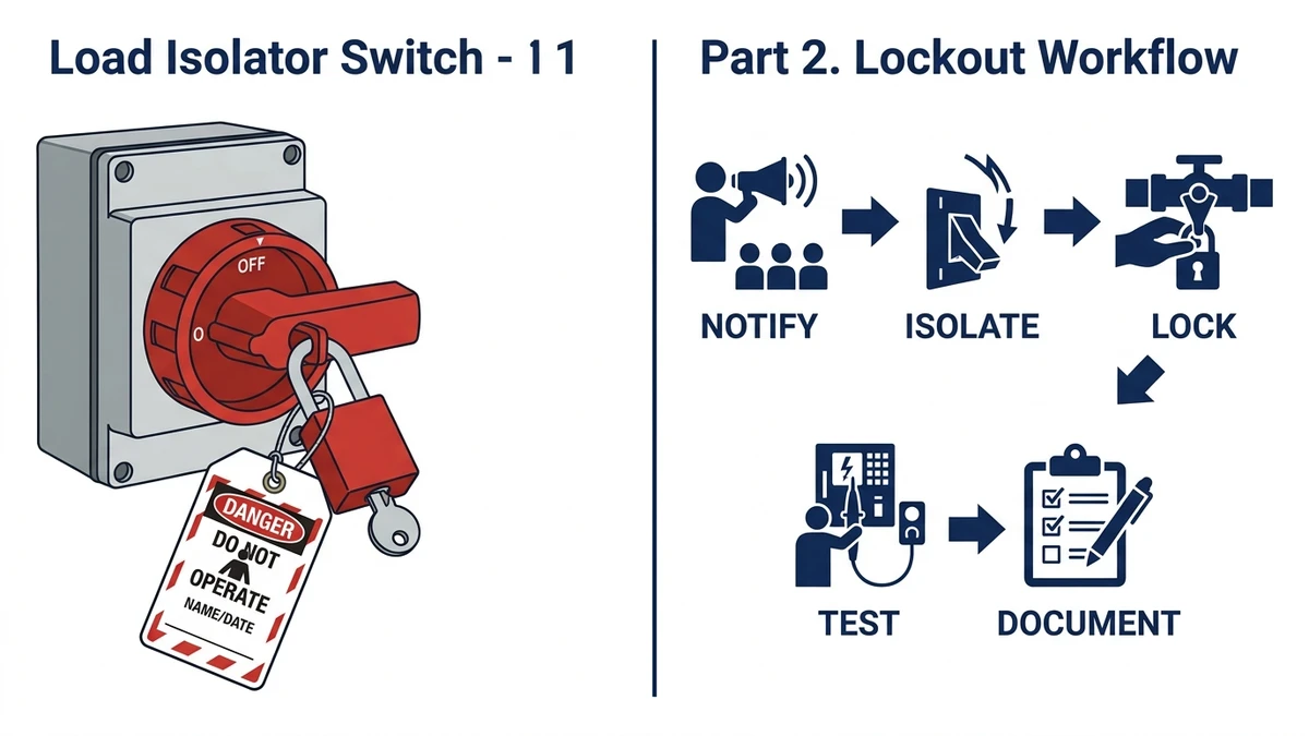
LOTO Procedure Checklist
Once the switch is installed, enforce this sequence before every maintenance task:
Notify all affected personnel that the circuit will be isolated.
Operate the isolator to the OFF/OPEN position.
Apply a personal padlock and attach a signed tagout label identifying the authorised worker and the date.
Test for absence of voltage using a rated voltmeter – confirm 0V AC at the load terminals.
Document the isolation event in the site maintenance log.
Lockout practice combines the OFF position, padlock, tag, absence-of-voltage test, and documentation.
Load Isolator Switches from Shieldhz: Rated, Certified, and Field-Ready
Every parameter covered in the preceding sections – current rating, utilization category, IP class, and LOTO compatibility – is addressed across the Shieldhz isolator range, designed for the real demands of motor control, HVAC, and pump applications.
Rotary Cam Switch Range
The SH30 rotary cam switch series covers rated currents from 10A up to 100 A at 690 V AC, supporting multi-position isolation schemes for motors, reversing contactors, and HVAC fan stages. For outdoor and wet-area isolation, the SHP and SH30 weatherproof isolator switch range provides IP66-rated enclosures suited to pump stations, rooftop units, and coastal installations.
Certifications and Compliance
Shieldhz supports common industrial documentation routes such as CE, IEC-aligned test data, RoHS, CCC, TUV, UL, UKCA, and CB where applicable to the exact product. Products are manufactured by Zhejiang Shihe Electric Co., Ltd. in Zhejiang Province, China, with a 5,000+ m2 production base, 100+ employees, and 40+ production machines. Buyers should request the current certificate and test document set for the specific part number.
Specify, Source, and Install with Confidence
Whether you are specifying a local isolation point for a 37 kW pump motor or sourcing panel-mount cam switches for an HVAC control cabinet, Shieldhz provides rated, documented product options across the full rotary cam switch and isolator range.
Browse the complete product range at shieldhz.com/products, or contact our technical team directly to discuss current rating, utilization category, enclosure protection class, and certification requirements for your specific application.
Frequently Asked Questions
What is the difference between a load isolator switch and a circuit breaker?
A load isolator switch is specifically designed to create a verified, lockable open-circuit state for safe maintenance access, whereas a circuit breaker is a protective device that trips automatically under fault conditions. While some circuit breakers include an isolation function, they are not classified as isolators under IEC 60947-3 unless they meet the defined isolating distance and withstand voltage requirements.
Can a load isolator switch interrupt a running motor without damaging the switch?
Yes, provided the switch is rated under IEC 60947-3 utilization category AC-23A, which certifies it to make and break inductive motor load currents, including the elevated currents associated with motors that have not been pre-stopped. Using a switch rated only for AC-21A or AC-22A on a running motor risks contact welding and premature failure.
How many poles does a load isolator switch need for a three-phase motor?
A three-phase motor circuit commonly uses a 3-pole isolator for the phase conductors. If the neutral must also be isolated under the project earthing and wiring rules, specify a 4-pole device. The contact program should match the system design, not just the number of incoming wires.
What IP rating is required for an outdoor HVAC isolator switch?
Rooftop and exposed outdoor locations commonly start at IP65, but the right rating depends on rain exposure, washdown, dust, UV, and cable-entry sealing. Sites with direct spray or harsh outdoor exposure may specify IP66 or IP67 as a higher-margin enclosure route.
Is a load isolator switch the same as a safety switch or RCD?
No – a load isolator switch disconnects all poles of a circuit to enable safe maintenance and does not detect or respond to earth faults. A residual current device (RCD) or safety switch monitors current imbalance between live conductors and trips when a leakage current threshold is exceeded, providing personal protection against electric shock rather than a lockable maintenance isolation point.
What does utilization category AC-23A mean on a load isolator switch?
AC-23A is an IEC 60947-3 utilization category used for switching motor loads and other highly inductive loads. For motor, compressor, and pump isolation duties, check whether AC-23A or another category is required by the application and confirm the value on the exact datasheet.
How close to the equipment should a load isolator switch be mounted?
Industry practice places the isolator where maintenance staff can clearly identify the equipment being isolated and verify the de-energized state. Exact distance and line-of-sight rules should be taken from the local wiring code and the site safety procedure.
Shi, Muxi
Shi, Muxi writes Shieldhz technical articles for industrial control and electrical component buyers, covering rotary cam switches, isolator switches, PV DC disconnects, push buttons, indicator lights, waterproof enclosures, and terminal blocks. The articles are based on Zhejiang Shihe Electric Co., Ltd.'s manufacturing and export experience, with practical emphasis on model selection, datasheets, drawings, certifications, IP ratings, and inquiry details buyers should confirm before ordering.