A rotary cam switch is a manually operated multi-position switch that uses a rotating shaft and internal cam-driven contacts to open, close, or transfer electrical circuits in a defined sequence. It is used for machine control, panel operation, motor function selection, changeover duties, and circuit isolation where clear switch positions and reliable contact logic matter.
Rotary cam switches are common in industrial control panels because they can combine several switching functions into one compact operator. For panel builders, buyers, and maintenance teams, the practical advantage is repeatable position-based switching logic, visible operator markings, and flexible contact arrangements in a single device.
A rotary cam switch converts shaft rotation into electrical contact changes. When the operator turns the handle, a cam mechanism inside the switch body pushes specific contact blocks into open or closed states. Each shaft angle corresponds to a preset contact pattern.
Unlike a basic on/off switch, the device can have multiple positions such as:
0-1
1-0-2
0-1-2-3
Forward-Off-Reverse
Star-Delta
Voltmeter phase selection
Ammeter phase selection
The internal cams determine which poles connect in each position. This is why rotary cam switches are often described by both their position scheme and their contact diagram.
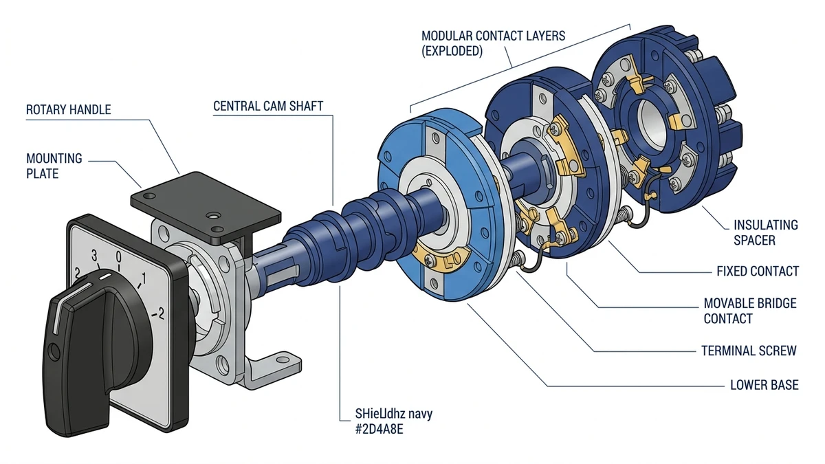
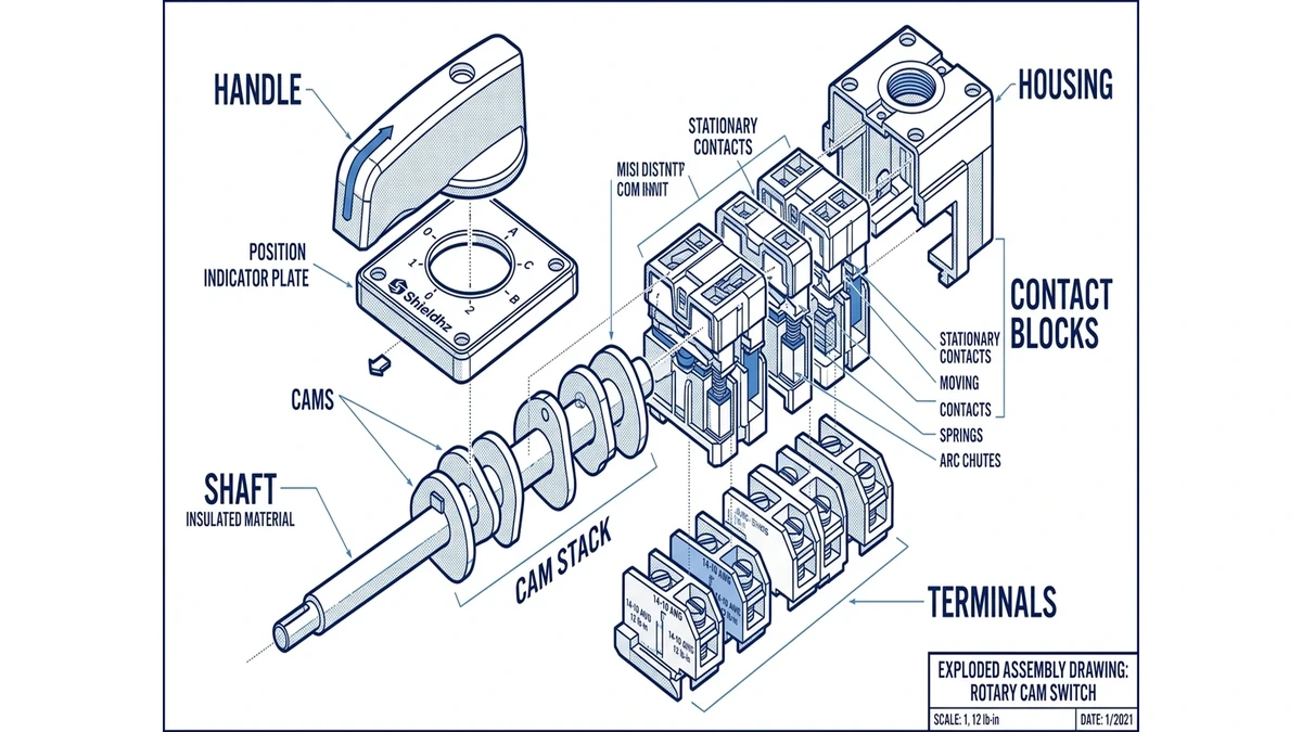
Main parts of a rotary cam switch
Although designs differ by series and manufacturer, most designs include these elements:
Operating handle or knob
Shaft
Cam stack
Contact blocks
Fixed and moving contacts
Housing or mounting frame
Terminal screws or other conductor terminations
Position indexing mechanism
Front plate or legend plate
The cam stack is the defining feature. Each cam profile controls one or more contacts, allowing the switch to perform a very specific sequence as the shaft rotates.
Main parts of a rotary cam switch
What functions can a rotary cam switch perform?
These switches are selected for function, not just current rating. A buyer usually starts by asking: what must happen at each handle position?
On/off isolation or disconnect switching.
Some rotary cam switches are used to switch a circuit on and off manually. Depending on the design and intended rating, they may be used as switch-disconnectors or control switches in low-voltage applications. The applicable product standard for low-voltage switches, disconnectors, switch-disconnectors, and fuse-combination units is IEC 60947-3. Suitability for isolation should always be confirmed from the product’s rating, markings, and manufacturer documentation rather than assumed from appearance alone.
Changeover switching.
A cam-operated switch can transfer a load or control circuit from one source or mode to another, such as:
Main supply to backup supply
Automatic to manual mode
Motor winding arrangement changes
Instrument circuit selection
Motor control selection.
Manual motor control functions often include:
Forward/Off/Reverse
Star/Delta transition
Multi-speed motor selection
For these duties, the switch’s utilization category, making and breaking capability, and wiring diagram are more important than nominal current alone.
Metering circuit selection.
This construction is often used as a selector switch for panel meters. Common examples include:
Voltmeter selector switch for L1-L2, L2-L3, L3-L1
Ammeter selector switch for phase current display
Earth fault or test selection in some control systems
Control logic and interlocking sequences.
A cam switch can provide a specific switching order that supports:
Step-by-step machine modes
Sequential control states
Auxiliary signalling contacts
Mechanical detent positions for operator feedback
Because the contact logic is pre-engineered into the cam arrangement, the switch can simplify panel wiring compared with multiple separate switches.
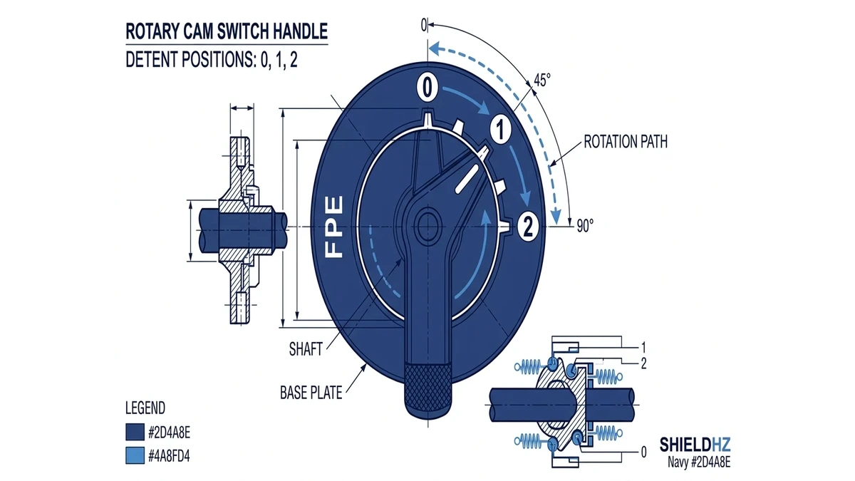
Understanding positions on a rotary cam switch
The term “positions” refers to the distinct detented handle locations. Each position corresponds to a defined contact state.
Examples:
2-position: OFF/ON
3-position: I-0-II
3-position motor control: Forward-0-Reverse
4-position selector: 0-1-2-3
Spring-return position: maintained in one direction, momentary in another
Position layout matters for both operation and safety. A maintenance engineer needs to know whether there is a true OFF state, whether adjacent positions overlap, and whether the switch is break-before-make or make-before-break.
Position numbering and legends
Front plates often use:
0, 1, 2, 3
I, 0, II
FWD, OFF, REV
STAR, 0, DELTA
R, S, T or phase notations for instrumentation
The legend must match the actual contact program. A mismatch between front marking and internal contact logic can lead to commissioning errors.
Contact logic: the most important selection detail
The contact logic is the electrical truth table of the switch. It defines which terminals are connected at each position.
This is what separates a rotary cam switch from a generic rotary knob. Two switches may look identical from the front but have completely different internal switching programs.
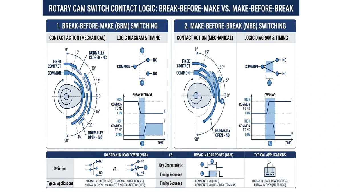
Break-before-make vs make-before-break
These two concepts are essential.
Break-before-make
The existing circuit opens before the new circuit closes. This helps prevent unwanted bridging between two circuits. It is common in source selection and many control functions where overlap would be unsafe.
Make-before-break
The new circuit closes before the previous one opens. This allows brief overlap and may be useful in some signal continuity applications. It is not suitable where two sources must never be tied together unless the switch is specifically designed for that duty.
Always verify the switching characteristic in the datasheet or wiring diagram.
Poles and contacts
The switch may be described by:
Number of poles
Number of switching positions
Contact arrangement
Special functions such as spring return or key operation
Examples:
1-pole 2-position
3-pole changeover
4-pole isolating switch
Multi-wafer selector with auxiliary contacts
As contact stacks increase, the switch can control several circuits at once. This is useful in complex machine control panels where one operator action must change both power and signal paths.
Contact sequence defines switching behavior
Typical applications
Cam-operated rotary switches appear across many industrial sectors because they can package manual switching logic into a compact panel device.
Industrial control panels: local mode selection, manual overrides, meter selection, and feeder isolation.
Pumps and HVAC equipment: Hand-Off-Auto selection, duty transfer, and fan speed or operational mode selection.
Power distribution and utility panels: selector or disconnect devices where manual circuit changeover or indication support is needed.
Generator and source selection systems: source selection or transfer logic in carefully engineered systems, provided the device is rated and configured for that duty.
Marine, agriculture, and mobile equipment: manual switching with clear detent positions and simple operator feedback.
For product families used in these applications, compare the required function, rating, handle style, and contact program before choosing a specific series.
Shieldhz product-line context for selection
Shieldhz separates rotary switching products by duty and installation route, which helps buyers avoid treating every cam-operated switch as the same device. Zhejiang Shihe Electric Co., Ltd. was founded in 2014 and manufactures industrial control components including cam switches, isolator switches, push buttons, indicator lights, and terminal accessories. For rotary switching projects, the useful product-line distinction is not only the front handle style; it is the rated duty, enclosure need, contact program, and documentation package behind the switch.
For general panel switching and selector duties, LW28 rotary cam switches are the usual starting point because the series covers common control-panel functions such as ON/OFF, changeover, and instrument selection. For heavier industrial panel routes, LW42 rotary cam switches are better reviewed when the application needs a more robust switching platform or a higher-duty configuration. For local isolation, HVAC, pumps, and outdoor-related switching routes, the SH30 rotary cam switch page is the more relevant starting point.
From an E-E-A-T perspective, the selection should be documented rather than guessed. A serious inquiry should include the required contact diagram, rated operational voltage, rated current, utilization category, front legend, mounting style, and expected environment. The supplier should then match the model to the duty and provide the wiring diagram or datasheet reference before the part is released for panel build.
How rotary cam switches differ from selector switches and isolators
The terms can overlap, so buyers should look at the function and rating rather than the name alone.
Rotary cam switch vs selector switch
A selector switch is a broad category of manually operated position switches. A rotary cam switch is a specific construction type that uses cams and contact blocks to create the switching program. Many panel selector switches are rotary cam switches, but not all selector switches are built the same way.
Rotary cam switch vs isolator
An isolator or disconnecting switch is generally expected to provide safe circuit separation under defined conditions. Some models are designed and rated for switch-disconnector duties, but others are intended only for control circuits or instrumentation selection. The device’s certification, utilization category, and intended use determine whether it is suitable for isolation.
Rotary cam switch vs circuit breaker
A circuit breaker provides protective tripping for overload or short circuit conditions. A cam-operated manual switch does not replace overcurrent protection unless part of a coordinated design with separate protection devices.
Selection basics: how to choose the right rotary cam switch
Procurement teams often compare only price, current, and handle style. That approach is risky. Correct selection starts with the switching duty.
1. Define the function position by position
Write down exactly what the switch must do in every handle position.
Example:
– Position 0: all motor control contacts open
– Position 1: forward contact closed, reverse open
– Position 2: reverse contact closed, forward open
This becomes the basis for the contact diagram.
2. Confirm the circuit type
Ask whether the switch is handling:
Main power
Motor load
Resistive load
Auxiliary control circuit
Metering circuit
Source transfer or changeover
The electrical duty affects the required rating and contact design.
3. Check rated operational voltage and current
Match the switch to the actual system voltage and operating current. Do not rely only on a headline ampere value. Operational ratings depend on the load type and utilization category.
4. Review utilization category
For low-voltage switchgear and controlgear, utilization categories indicate the kind of duty the device can handle. For example, a switch used in a motor circuit may need a different rating basis than one used in a resistive or control circuit. IEC 60947-3 is the key reference framework for many low-voltage switching devices and duty classifications; current product documentation should be checked for exact applicability and test ratings.
5. Verify contact program and switching angle
Two switches with the same current rating may behave differently because of different cam arrangements. Confirm:
Contact truth table
Pole count
Terminal numbering
Switching sequence
Overlap or non-overlap behavior
Number of detent positions
Total angle of rotation
6. Check mounting style and dimensions
Panel design affects selection:
Front mounting or base mounting
Door-coupling handle requirements
Panel cutout
Depth behind panel
Terminal access space
IP protection needs for operator handle area
7. Consider environmental conditions
For industrial sites, review:
Ambient temperature
Humidity
Dust
Vibration
Corrosive atmosphere
Frequency of operation
A switch that is acceptable in a clean indoor meter panel may not be ideal for a harsh machine environment.
8. Confirm compliance documentation
Buyers should request or review:
Technical datasheet
Wiring diagram
Product ratings
Standard references
Routine quality documentation where relevant
If IEC references are important to your project, the official source for standards publication information is IEC Webstore.
Why IEC 60947-3 matters
IEC 60947-3 is the widely referenced standard family document for low-voltage switches, disconnectors, switch-disconnectors, and fuse-combination units. For rotary cam switches, it matters because some products in this category may be designed and tested for duties covered by that standard.
A few practical points:
Not every rotary cam switch serves the same purpose.
A switch used only for metering selection is not automatically equivalent to a switch-disconnector.
Isolation suitability must be supported by product ratings and markings.
Motor switching performance depends on the duty and declared utilization category.
Procurement specifications should state the required function, not just “rotary switch”.
The safest approach is to match the application requirement to the product’s declared electrical performance.
Selection should match function, duty, and verified ratings
Common mistakes when specifying rotary cam switches
Choosing by ampere value alone: a 20 A switch for resistive duty is not automatically suitable for motor switching or source transfer.
Ignoring contact sequence: if overlap behavior is wrong, the switch may short two sources, create false control states, or interrupt a process unexpectedly.
Forgetting the OFF position requirement: many applications need a true neutral or isolated center position. Others do not.
Using the wrong legend plate: the operator marking must reflect the actual switching program.
Overlooking panel space: a compact front operator can still require significant depth behind the panel.
Assuming all rotary switches meet the same standard scope: the intended use and tested performance determine compliance suitability.
Practical buying checklist
Before ordering, confirm these items:
What is the exact function in each position?
How many poles are required?
Is the duty power, motor, control, or metering?
Is break-before-make required?
Is a center OFF needed?
What are the voltage and current values in service?
What utilization category is required?
Does the application require isolation capability?
What mounting method is needed?
What are the environmental conditions?
Is a standard contact program sufficient, or is a special program needed?
If you need help matching a switch program to an application or panel layout, contact Shieldhz.
Final takeaway
A rotary cam switch is a position-based manual switching device that uses internal cams to control a specific contact sequence. Its real value lies in the combination of clear operator positions, configurable contact logic, and suitability for many low-voltage control and switching tasks. Good selection depends on function, duty, contact program, and verified ratings, especially when IEC 60947-3-related performance or isolation duties are part of the requirement.
FAQ
What is a rotary cam switch used for?
It is used for manual circuit selection, changeover, motor control functions, metering selection, and some disconnect or switch-disconnector duties when the product is rated for that use.
How does a rotary cam switch work?
It works by rotating a shaft that drives internal cams. The cams open and close specific contacts in a preset sequence at each handle position.
What do the positions on a rotary cam switch mean?
Each position is a detented handle setting such as 0, 1, 2, Forward, or Reverse. Every position corresponds to a defined contact arrangement inside the switch.
Is a rotary cam switch the same as an isolator?
Not always. Some rotary cam switches are suitable for isolating or switch-disconnector duties, while others are intended only for control or metering circuits. The rating and product documentation decide this.
Why is contact logic important when selecting a rotary cam switch?
Contact logic determines which terminals connect in each position. It affects machine behavior, source transfer safety, interlocking, and whether the switch is break-before-make or make-before-break.
What standard is relevant for low-voltage rotary switch duties?
IEC 60947-3 is the key standard reference for low-voltage switches, disconnectors, and switch-disconnectors. Product suitability should be confirmed from the manufacturer’s declared ratings and documentation.
Shi, Muxi
Shi, Muxi writes Shieldhz technical articles for industrial control and electrical component buyers, covering rotary cam switches, isolator switches, PV DC disconnects, push buttons, indicator lights, waterproof enclosures, and terminal blocks. The articles are based on Zhejiang Shihe Electric Co., Ltd.'s manufacturing and export experience, with practical emphasis on model selection, datasheets, drawings, certifications, IP ratings, and inquiry details buyers should confirm before ordering.