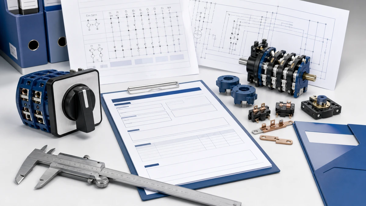
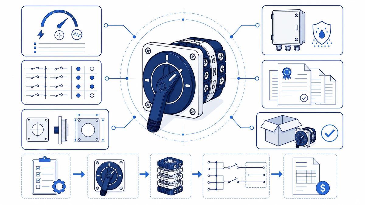
Para solicitar um diagrama de fiação verificado e uma cotação competitiva para uma chave de came rotativa, são necessárias cinco entradas confirmadas antes de entrar em contato com qualquer fornecedor: tensão operacional, corrente nominal, número de polos, sequência de posições e classificação IP do gabinete. Esses parâmetros definem o código do modelo de chave de came rotativo e permitem que uma equipe de engenharia retorne um diagrama de fiação correspondente, uma tabela de contatos e uma cotação formal em uma única resposta. A omissão de qualquer uma dessas entradas normalmente aciona pelo menos uma rodada de e-mails de esclarecimento, o que atrasa tanto o diagrama quanto o preço. Este guia explica como reunir essas informações, decodificar um código de modelo existente, ler a tabela de contatos e enviar uma consulta completa à Shieldhz.
Quais informações devem ser coletadas antes de solicitar um código de modelo e um orçamento
Antes de abrir uma consulta, confirme os cinco parâmetros que orientam cada campo de código de modelo. Extrair esses parâmetros dos documentos de origem, em vez de usar a memória, evita os atrasos mais comuns nas cotações.
Tensão operacional e corrente nominal
Os dois parâmetros elétricos mais críticos são a tensão operacional nominal e a corrente nominal. Para chaves seletoras de várias posições em conformidade com a IEC, a tensão nominal de isolamento (Ui) pode atingir até 690 V CA, dependendo da série e do projeto do suporte de contato. As estruturas de corrente nas linhas comuns de chaves seletoras industriais variam de 10 A a 63 A. Leia ambos os valores na placa de identificação do motor ou no diagrama de circuito do painel, em vez de ler os valores estimados de carga, pois a categoria de utilização depende do fato de a chave fazer e interromper cargas resistivas, mistas ou motoras.
IEC 60947-3:2020+AMD1:2025 aplica-se a chaves, seccionadores, chaves seccionadoras e unidades de combinação de fusíveis para circuitos de distribuição e motores com tensão nominal de até 1000 V CA ou 1500 V CC. A confirmação de que o seu interruptor se enquadra nesse escopo é o primeiro ponto de verificação de conformidade antes de selecionar um quadro.
Sequência de posições e contagem de polos
O programa de contato de um comutador de came rotativo é definido pelo número de posições comutadas que ele oferece e pelo número de polos engatados em cada posição. Para aplicações de reversão do motor ou partida estrela-triângulo, o programa de contato deve corresponder exatamente ao diagrama do circuito. Confirme o número de posições, o passo angular entre os detentores (geralmente 45 graus ou 90 graus, dependendo da série) e se é necessária uma ação de retorno por mola. Uma chave encomendada com o número de posições errado ou com um passo angular incorreto não pode ser corrigida no campo sem uma substituição completa.
Categoria de utilização
Indique explicitamente a categoria de utilização em vez de descrever a carga em linguagem simples. A AC-21A abrange cargas resistivas e levemente indutivas com sobrecorrente moderada. A AC-22A abrange cargas mistas resistivas e indutivas. A AC-23A abrange a comutação de motores com gaiola de esquilo, em que a corrente de abertura pode atingir de seis a oito vezes a corrente nominal de funcionamento. Rotular a consulta com a categoria correta garante que o material de contato e a geometria de extinção de arco sejam dimensionados para o serviço de comutação real, e não apenas para a corrente de estado estável.
Requisitos de gabinete e certificação
Especifique a classificação IP necessária antes de escolher entre uma estrutura de montagem em painel padrão e uma configuração à prova de intempéries. Para ambientes externos ou de lavagem, o IP65 é um requisito mínimo comum; instalações sujeitas a imersão temporária exigem IP67 ou IP68 de acordo com a norma IEC 60529. Observe todas as certificações de mercado necessárias - CE, CCC, RoHS, equivalência UL ou relatórios de teste TUV - porque a disponibilidade do certificado afeta o pacote de documentação e, em alguns casos, afeta a rota de produção.
Figura 1. Conceito central por trás da seleção do código do modelo de chave de came rotativo.
Como os códigos de modelo de chave de came rotativo são estruturados
Com os cinco parâmetros de entrada confirmados, você pode decodificar um código de placa de identificação existente ou criar um novo. Um código de modelo é uma cadeia de especificações comprimida que codifica todos os parâmetros configuráveis em uma única referência. A leitura incorreta de um campo produz um interruptor com a sequência de contatos errada ou com a contagem de polos errada, e é por isso que a alfabetização do código do modelo é tão importante durante a compra de um substituto quanto durante o projeto inicial do painel.
Identificador de série
Os caracteres de abertura definem a família do produto e a estrutura mecânica. Os Série LW28 e o Série LW42 são duas famílias distintas com geometria de came, dimensões do suporte de contato e requisitos de corte do painel diferentes. A substituição de uma estrutura pela outra sem verificar o desenho de montagem pode invalidar o ajuste em um painel de controle existente, mesmo que as classificações elétricas pareçam idênticas.
Campo de classificação atual
Imediatamente após o prefixo da série, um campo numérico especifica a corrente operacional nominal em amperes. Confirmar esse campo com a placa de identificação do motor ou com a programação de carga é a primeira etapa do diagnóstico quando há suspeita de que um interruptor de substituição esteja sendo subestimado. Não substitua uma estrutura de classificação inferior simplesmente porque ela se encaixa no mesmo recorte do painel.
Programa de contato e código do cargo
Esse campo define o número de posições da chave e o estado aberto ou fechado de cada contato em cada passo do came. Na prática de manutenção, um diagrama de fiação é gerado diretamente a partir desse código - cada coluna de posição é mapeada para um ângulo de came distinto. Uma incompatibilidade entre o programa de contatos instalado e o desenho do circuito é uma das fontes mais comuns de falhas no circuito de controle em partidas de motores de várias posições. Ao decodificar uma placa de identificação no campo, o segmento do código que segue a barra é normalmente o campo mais útil para o diagnóstico; confirme-o primeiro antes de solicitar um diagrama de substituição.
Contagem de polos e opções auxiliares
Os campos finais indicam a contagem de polos e qualquer contato auxiliar ou variante de gabinete. Para aplicações externas, um sufixo de classificação IP distingue uma unidade de montagem em painel de um conjunto à prova de intempéries. Navegue pelo Faixa completa de interruptor de came rotativo para fazer referência cruzada de séries, contagem de polos e opções de gabinetes antes de enviar uma solicitação de orçamento.
Como ler a tabela de contatos e solicitar o diagrama de fiação correto
Ler corretamente o diagrama de fiação de um interruptor de came rotativo é o primeiro passo para solucionar falhas de contato, verificar a compatibilidade da substituição e colocar em funcionamento um novo painel de interruptores de várias posições.
Etapa 1: Localize e decodifique o código do modelo
Encontre o código do modelo na placa de identificação do switch ou na documentação original de compra. Cada segmento de caractere é mapeado para um parâmetro definido. Se a placa de identificação estiver ilegível devido a danos causados pelo calor, fotografe a sequência de camadas do disco de came diretamente: o número de camadas do disco de came é igual à contagem de polos e a geometria do lóbulo em cada disco identifica a família do programa de contato. Trate a configuração física do came como a verdade fundamental sempre que uma placa de identificação e um diagrama de circuito não estiverem de acordo, especialmente após um retrofit de painel em que pode ter ocorrido uma nova rotulagem.
Etapa 2: Interpretar a tabela de contatos
A tabela de contatos é o núcleo de qualquer diagrama de fiação de interruptor de came. Cada linha representa um par de contatos; cada coluna representa uma posição do comutador. Uma célula preenchida indica que o contato está fechado naquela posição; uma célula vazia indica que está aberto. Ao solucionar problemas, compare sistematicamente os resultados de continuidade medidos com a tabela, testando cada par de contatos em cada posição usando um ohmímetro de baixa resistência. Um desvio em uma posição específica normalmente indica desgaste do came, fadiga da mola ou oxidação do contato confinada àquela camada, em vez de uma falha sistêmica em toda a unidade.
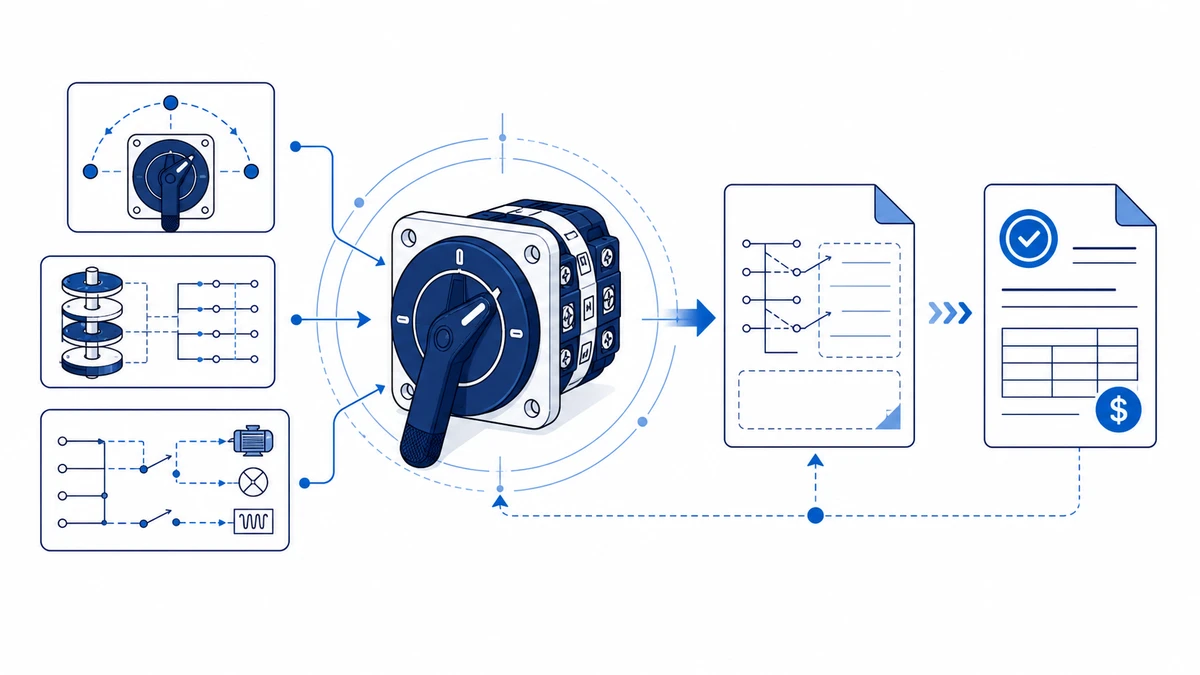
Figura 2. As verificações de seleção devem conectar a função do interruptor, a classificação, a sequência de contatos, a rota de montagem e a documentação.
Etapa 3: Solicite o diagrama correto
Ao entrar em contato com o fornecedor, forneça todos os itens a seguir para receber um diagrama de fiação verificado em uma única resposta:
Código de modelo completo da placa de identificação ou reconstruído a partir de inspeção física
Número de posições e sequência de comutação, por exemplo, uma sequência de 3 posições rotuladas como 0, I e II
Tensão e corrente nominais, por exemplo, 20 A a 380 V CA
Tipo de aplicação: reversão do motor, seletor, isolador ou comutador
Se é necessário um desenho de corte do painel ou documentação de conformidade com a IEC 60947-3 junto com o diagrama
Para LW42 ou Série SH30 Comutadores, a especificação do requisito de documentação no primeiro ponto de contato evita um segundo ciclo de solicitação e acelera a programação da manutenção.
Passo a passo: Como enviar uma consulta sobre o interruptor de came para obter uma resposta rápida e precisa
Uma consulta completa no primeiro contato elimina a fonte mais comum de atrasos na cotação. As cinco etapas abaixo mapeiam cada entrada para o campo que ela afeta no código do modelo e no pacote de documentação.
Etapa 1: Identificar a série do switch e o tamanho da estrutura
Confirme qual família de produtos se aplica ao seu painel. A série LW28 abrange recortes de painéis compactos e funções gerais de chaves seletoras de várias posições. A série LW42 atende a aplicações de controle de motores industriais de corrente mais alta com uma estrutura de suporte de contato maior. Inclua o número necessário de posições e o tipo de alavanca de operação, como punho de pistola, botão ou atuador operado por chave, pois o tipo de alavanca afeta as dimensões de montagem e as provisões de bloqueio.
Etapa 2: Especificar parâmetros elétricos
Informe a tensão operacional nominal, o tipo de carga e a categoria de utilização. Para controle de motor CA, confirme se a carga se enquadra em CA-21A, CA-22A ou CA-23A, conforme definido na IEC 60947-3:2020+AMD1:2025. Inclua a corrente nominal em amperes e a tensão de isolamento nominal Ui para confirmar a coordenação do isolamento com o restante do conjunto do painel.
Etapa 3: Definir o programa de contato
Anexe ou descreva a sequência de comutação de contato necessária para cada posição do came. Uma grade mostrando quais polos são fechados em cada posição angular - por exemplo, 0 graus, 45 graus, 90 graus - permite que a equipe de engenharia corresponda imediatamente a um perfil de came existente ou sinalize um requisito de programa de contato personalizado. Um esboço leva menos de dois minutos para ser preparado e substitui várias rodadas de descrição por escrito que são difíceis de verificar sem um visual.
Etapa 4: Confirmar as necessidades de ambiente e documentação
Especifique a classificação IP exigida e o conjunto de certificados ou relatórios de teste necessários para seu mercado. Os requisitos comuns incluem a declaração de conformidade CE, a declaração de conformidade RoHS, o certificado CCC para o mercado chinês ou um relatório de teste de terceiros. A declaração antecipada desses requisitos permite que a equipe de engenharia confirme a disponibilidade antes da emissão da cotação, e não depois que o pedido é feito.
Etapa 5: Envie pelo canal de consulta técnica
Envie a especificação compilada - série, posições, classificação de corrente, tabela de contatos, requisitos de IP e lista de documentação - por meio do Página de contato da Shieldhz. Anexe todos os diagramas de fiação existentes, fotografias da placa de identificação ou folhas de dados do motor. As solicitações com dados completos enviadas nesse estágio permitem que a equipe de engenharia retorne um código de modelo confirmado, um diagrama de fiação e uma cotação em uma única resposta, em vez de várias trocas.
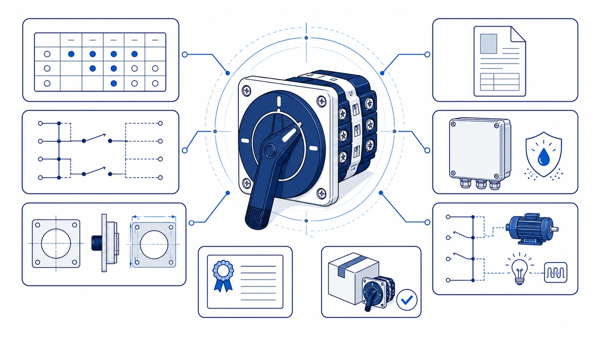
Figura 3. O contexto da fiação da aplicação deve ser verificado com base na tabela de contatos do fabricante antes da energização.
Como a Shieldhz confirma seu código de modelo, diagrama e pacote de documentação
Shieldhz é a marca de exportação da Zhejiang Shihe Electric Co., Ltd., fundada em 2014 e operando em uma instalação de mais de 5.000 metros quadrados em Yueqing, Zhejiang, com mais de 100 funcionários e 40 máquinas de produção. A empresa possui certificação de gerenciamento de qualidade ISO 9001 e exporta produtos com documentação CE, RoHS, TUV, UL, UKCA, CCC e CB, dependendo do modelo e do mercado de destino.
Depois que uma consulta completa é recebida, uma sequência estruturada de confirmação interna garante que o código do modelo final, o diagrama de fiação e o pacote de documentação estejam alinhados antes do início da produção ou da remessa. A compreensão de cada estágio ajuda os compradores a prever o tempo e evitar atrasos causados por especificações incompletas.
Triagem de consulta e validação de entrada
O processo começa quando um comprador envia informações técnicas. No mínimo, a consulta deve incluir a tensão operacional, a corrente nominal, o número de posições, a contagem de polos, a categoria de utilização, o requisito de classificação IP do gabinete e as certificações necessárias. Para configurações complexas de várias posições, um esboço do programa de contato ou um diagrama de circuito existente reduz significativamente o ciclo de análise. A equipe de engenharia sinaliza todas as entradas que estão fora de uma faixa de programa de contato padrão antes do estágio de confirmação do código do modelo.
Verificação do código do modelo e verificação da capacidade de construção
A equipe técnica faz uma referência cruzada dos parâmetros enviados com as tabelas de contatos da série de chaves de came, confirmando se a sequência de posições solicitada pode ser obtida dentro dos limites do programa de polos e contatos da estrutura especificada. A tensão nominal de isolamento Ui e a tensão nominal de resistência a impulsos Uimp são verificadas em relação à tensão do sistema do comprador. Se uma configuração solicitada estiver fora de um programa padrão, a equipe identificará a variante mais próxima que pode ser construída ou sinalizará um requisito de came personalizado com um prazo de entrega adicional estimado.
Confirmação do diagrama de fiação e do pacote de desenhos
Depois que o código do modelo é validado, um diagrama de fiação correspondente a esse programa de contato específico é preparado juntamente com um desenho de corte do painel e uma folha de dimensões de montagem. Para a série LW42 ou outros interruptores de estrutura maior, o pacote de documentação inclui uma tabela de posições de contato que mostra os estados aberto e fechado em todas as posições do interruptor. As equipes de manutenção usam essa tabela diretamente durante a solução de problemas e o comissionamento de substituição, sem a necessidade de entrar em contato com o fornecedor novamente.
Emissão de cotação com referência de documentação
Uma cotação confirmada faz referência à sequência exata do código do modelo, à revisão do desenho, às certificações aplicáveis e ao prazo de entrega. O tempo de confirmação depende da integridade dos dados, da rota do estoque e do fato de o programa de contato ser padrão ou exigir revisão de engenharia. Esse conjunto de documentos rastreáveis permite que a equipe de manutenção verifique uma substituição futura em relação à especificação original, sem precisar enviar novamente uma consulta completa.
Solução de problemas de um interruptor de came existente antes de solicitar uma cotação de substituição
A exclusão sistemática de falhas reparáveis em campo antes de enviar uma cotação de substituição economiza tempo de aquisição e evita pedidos desnecessários de peças. As verificações abaixo abrangem os quatro modos mais comuns de falha do comutador de came em aplicações industriais de controle de motores e comutação de painéis.
Resistência de contato e falhas de continuidade
Meça a resistência de contato em cada ponte de contato fechada usando um ohmímetro de baixa resistência. A resistência de contato aceitável para contatos de liga de prata sob força de contato nominal depende da folha de dados e deve ser confirmada com base na especificação publicada pelo fabricante para a série específica. As leituras significativamente acima do limite especificado normalmente indicam oxidação, depósitos de carbono ou desgaste do contato. Limpe os contatos acessíveis com álcool isopropílico com 99% de pureza ou mais e teste novamente antes de concluir que o conjunto de contatos precisa ser substituído.
Falhas mecânicas de posição e detenção
Gire o eixo do atuador em todas as posições de comutação e verifique se há engate incompleto do detentor, em que o eixo para entre as posições em vez de indexar de forma limpa. Verifique também se há discos de came rachados ou deformados, que às vezes são visíveis através da janela do suporte de contato, dependendo do projeto do invólucro, e se há falha na vedação do eixo em gabinetes com classificação IP mais alta, o que pode permitir a entrada de umidade e fazer com que o suporte do came inche. Nas variantes com retorno por mola, confirme se a mola de retorno restaura o eixo de forma limpa para a posição neutra em condições sem carga.
Um disco de came rachado não é uma condição reparável em campo. Documente a contagem de posições e a configuração dos polos na placa de identificação antes de solicitar uma substituição.
Verificação da resistência do isolamento
Usando o método de teste de isolamento aprovado pelo procedimento de manutenção do painel, verifique a resistência do isolamento entre cada par de contatos abertos e entre os polos e o terra. Compare o resultado com a folha de dados da chave, com o procedimento de manutenção aplicável e com o julgamento de um técnico qualificado; leituras anormais podem indicar entrada de umidade ou danos de rastreamento no suporte do contato e podem exigir a substituição completa da unidade em vez da limpeza do contato.
Integridade da fiação e dos terminais
Inspecione todos os parafusos dos terminais e confirme o torque de aperto com a folha de dados do fabricante para o tamanho específico da estrutura, pois os requisitos de torque variam de acordo com as classificações de corrente e os projetos dos terminais. Terminais soltos causam falhas intermitentes que imitam a falha de contato no campo. O isolamento descolorido ou as superfícies dos terminais com marcas de calor indicam condições de sobrecarga sustentada que devem ser investigadas antes que uma unidade de substituição seja energizada.
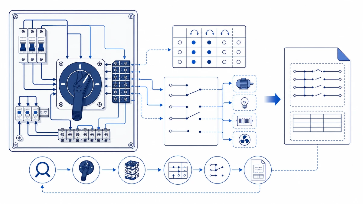
Figura 4. Uma consulta completa deve incluir a classificação, a sequência de contatos, a montagem, o invólucro e os requisitos de documentação.
Se todas as quatro verificações forem aprovadas, mas o circuito continuar funcionando mal, a falha provavelmente está fora do próprio interruptor do came. Analise o diagrama de fiação e o programa de contato em relação às conexões reais do circuito antes de passar para uma solicitação de substituição.
Perguntas frequentes
Quais são as informações mínimas necessárias para obter um diagrama de fiação de um interruptor de came rotativo?
Você precisa do código completo do modelo da placa de identificação, do número de posições da chave e da tensão e corrente nominais. Fornecer o tipo de aplicação - como reversão do motor, partida estrela-triângulo ou comutação geral do seletor - permite que o fornecedor faça uma verificação cruzada do programa de contato em relação ao dever declarado antes de emitir o diagrama, o que reduz a chance de receber um documento incorreto.
Como identificar o programa de contato de um interruptor de came com uma placa de identificação ilegível?
Conte o número de camadas do disco de came para determinar a contagem de polos e, em seguida, passe manualmente o eixo do atuador por cada posição enquanto sonda a continuidade em cada par de contatos com um ohmímetro de baixa resistência. Registre os resultados como uma grade mostrando quais pares estão fechados em cada posição. O envio dessa tabela de contatos reconstruída a um fornecedor fornece informações suficientes para corresponder a um programa existente ou confirmar se é necessária uma construção personalizada.
O que significa a categoria de utilização AC-23A e por que ela é importante na especificação de um interruptor de came?
O AC-23A designa um interruptor classificado para fazer e interromper a corrente total de partida de motores de indução com gaiola de esquilo, que pode atingir de seis a oito vezes a corrente nominal de funcionamento durante o transiente de partida. A especificação do AC-23A em vez do AC-21A garante que o material do contato, a geometria da lacuna de contato e as provisões de resfriamento de arco sejam compatíveis com o serviço de comutação real. O uso de um interruptor de classificação mais leve em um circuito de comutação de motor acelera a erosão do contato e aumenta o risco de soldagem em condições de falha.
Um interruptor de came rotativo pode ser reparado em campo ou sempre precisa ser substituído?
Os contatos oxidados ou sujos de carbono podem, às vezes, ser limpos e voltar a funcionar se as medições de resistência confirmarem que eles voltam a ficar dentro do limite especificado pelo fabricante após o tratamento. Um disco de came rachado, uma falha na vedação do eixo que permita a entrada de umidade ou danos de rastreamento no corpo de isolamento do transportador de contato são condições que exigem a substituição completa da unidade. A tentativa de continuar operando um interruptor com um disco de came rachado pode causar falhas de ponte de posição para posição no circuito controlado.
Qual classificação IP devo especificar para um interruptor de came em um painel de controle de motor externo?
O IP65 é o padrão mínimo para ambientes externos ou de lavagem de acordo com a norma IEC 60529, fornecendo exclusão total de poeira e proteção contra jatos de água de qualquer direção. As instalações sujeitas a imersão temporária devem especificar IP67 e considerar se um gabinete dedicado à prova de intempéries é apropriado para o local. Confirme se a classificação IP se aplica à unidade montada completa, incluindo a vedação do atuador e a tampa do terminal, e não apenas ao compartimento do suporte de contato.
Quanto tempo leva para receber um código de modelo confirmado e uma cotação da Shieldhz?
As configurações padrão com entradas técnicas completas geralmente podem ser confirmadas mais rapidamente do que as solicitações incompletas ou fora do padrão. As solicitações de programas de contato complexos exigem a verificação da capacidade de construção antes da emissão de uma cotação. O envio de uma foto da placa de identificação, um diagrama de fiação existente e uma tabela de contatos preenchida com a primeira solicitação reduz significativamente o ciclo de revisão das configurações padrão e personalizadas.
Qual é a principal diferença entre as séries de chaves de came rotativas LW28 e LW42?
A série LW28 foi projetada para recortes de painéis compactos e funções gerais de chaves seletoras de várias posições em uma variedade de configurações de polos e posições. A série LW42 acomoda aplicações de controle de motores industriais de corrente mais alta em uma estrutura de suporte de contato maior, com dimensões de recorte de painel e padrões de orifícios de montagem correspondentemente diferentes. Para alternar entre as séries, é necessário verificar o desenho do recorte do painel antes de fazer o pedido, pois as duas estruturas não são dimensionalmente intercambiáveis. Use as páginas das séries mencionadas acima para comparar os parâmetros da estrutura antes de enviar uma consulta.
Shi, Muxi
Shi, Muxi escreve artigos técnicos da Shieldhz para compradores de controle industrial e componentes elétricos, abrangendo chaves de came rotativas, chaves isoladoras, seccionadores PV DC, botões de pressão, luzes indicadoras, gabinetes à prova d'água e blocos de terminais. Os artigos são baseados na experiência de fabricação e exportação da Zhejiang Shihe Electric Co., Ltd., com ênfase prática na seleção de modelos, planilhas de dados, desenhos, certificações, classificações de IP e detalhes de consulta que os compradores devem confirmar antes de fazer o pedido.