Confirm the available control voltage before choosing an indicator-light variant.
Use colour as an operating-state convention, then verify the project specification and panel standard.
Check the drawing for cutout, ingress protection, terminal arrangement, and the compatible lamp or LED module.
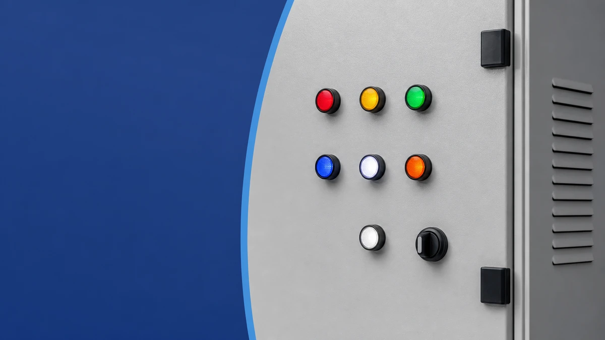
Selecting the correct indicator light for a control cabinet requires two decisions made in sequence: match the lamp voltage to the available control circuit supply, then assign lens colors following IEC 60073. For most modern panels, operating voltages are 24V DC, 110V AC, or 230V AC. IEC 60073 maps green to safe or normal, red to danger or fault, yellow to abnormal or caution, blue to mandatory action, and white to general status. Getting both decisions right before ordering prevents field rework, failed inspections, and operator confusion. This guide covers voltage selection, color standards, lamp technology comparison, a buyer checklist, and Shieldhz specification confirmation practice for the AD16 panel indicator light family.
Содержание
Indicator Light Voltage Selection: AC, DC, and Common Nominal Values
IEC 60073 Color Standards: What Each Color Signals
Lamp Technology Comparison: LED, Incandescent, and Neon
Buyer Checklist: Matching Indicator Lights to a Control Cabinet Specification
How Shieldhz Confirms Indicator Light Specifications Before Shipment
Часто задаваемые вопросы
Indicator Light Voltage Selection: AC, DC, and Common Nominal Values
Voltage selection is the first and most technically critical step in indicator light specification. Applying the wrong supply voltage to an LED indicator light can cause immediate driver failure, dielectric breakdown across the lamp holder insulation, or persistent ghost illumination that misleads operators. The lamp voltage must match both the nominal value and the supply type — AC or DC — available at the indicator terminal.
AC vs DC Supply: Core Differences
AC-rated indicator lights incorporate a rectifier bridge or purpose-built LED driver designed to tolerate continuous polarity reversal at 50 Hz or 60 Hz. DC-rated units require correct polarity at installation; reversing the connections on a polarity-sensitive LED module will prevent illumination or damage the driver immediately. DC 24V systems are standard in PLC-controlled panels, machine safety circuits, and modern motor control centers where a DIN-rail SMPS supplies a stable low-voltage control rail. AC 110V and 230V supply voltages remain common in power distribution panels and older installations where a dedicated control transformer is not present.
Applying AC voltage to a DC-only LED module causes rectification failure. Connecting a 24V-rated unit to a 230V AC circuit exceeds the rated insulation voltage and risks dielectric breakdown across the lamp holder assembly. These are not theoretical concerns — they are the two most common field damage modes for misspecified indicator lights.
Voltage Specification Reference Table
Nominal Voltage
Supply Type
Typical Operating Range
Lamp Type
Типовое применение
24V DC
DC
20-30V DC
LED
PLC panels, machine control, safety circuits
24V AC
AC
20-28V AC
LED, neon
Control transformers, relay panels
110V AC
AC
85-130V AC
LED, incandescent
North American control panels, HVAC
230V AC
AC
195-253V AC
LED, neon
European industrial panels, MCC switchboards
48V DC
DC
40-56V DC
LED
Telecom racks, DC distribution boards
12V DC
DC
10-15V DC
LED
Embedded systems, low-voltage machinery
Confirm the rated voltage tolerance band from the product datasheet before specifying. The Световой индикатор панели AD16 series offers 24V DC, 110V AC, and 230V AC variants that share the same panel cutout diameter but use internally different driver circuits. Substituting one voltage variant for another in the field is not interchangeable and is not supported by the product datasheet.
In a typical motor control center, a common approach is to power all indicator lights from the 24V DC control rail supplied by a DIN-rail power supply, keeping lamp voltage separated from the 230V AC main circuit. This simplifies wiring, reduces shock risk during lamp replacement, and aligns with IEC 60447 control circuit identification practices.
Practical Voltage Selection Notes
Always measure actual panel supply voltage under load before ordering indicator lights. A nominal 24V DC rail can sag below 21V or spike above 27V depending on SMPS regulation quality and cable run length. If the declared operating range of the selected indicator is 20-28V DC, a rail that spikes to 27.5V remains within specification — but only if you have confirmed the actual band from the datasheet, not assumed it.
For AC-fed panels without a control transformer, consider LED indicators rated for wide-range AC input to cover both 110V and 230V sites with a single stocked part. Verify whether the driver includes a built-in bleeder resistor; without it, ghost voltages from capacitive coupling in long cable runs can keep LEDs dimly lit even when the control signal is off. This is a particularly common issue in cabinets with cable runs exceeding 20 m on AC circuits.
Label voltage variants permanently during installation. The lens color and body profile of a 24V DC unit and a 110V AC unit from the same product family are visually identical in a parts bin. Errors made during maintenance replacements are a well-documented source of indicator light failures in the field.
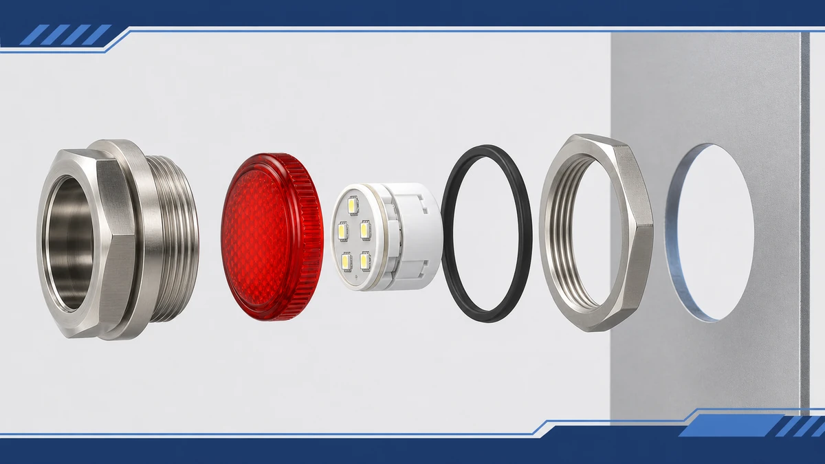
Indicator Light Voltage and Color Selection for Control Cabinets: engineering anatomy reference for technical selection.
IEC 60073 Color Standards: What Each Color Signals
IEC 60073 is the International Electrotechnical Commission standard governing the coding of indicators and actuators by color, shape, and marking. For indicator light color selection in control cabinets, it defines a mandatory color-to-machine-state mapping that engineers must follow to ensure operator safety and regulatory compliance across industrial installations worldwide. IEC 60204-1, the machine safety standard covering electrical equipment of machines, references IEC 60073 as a normative requirement, meaning compliance is mandatory wherever IEC 60204-1 applies — which covers the majority of industrial equipment sold into EU, UK, and many Asia-Pacific markets.
IEC 60073 Color-to-Machine-State Reference Table
Цвет
Machine State
Действия оператора
Красный
Danger, emergency, critical fault
Immediate intervention required
Yellow / Amber
Warning, abnormal condition
Monitor or take precautionary action
Зеленый
Safe, normal, ready to operate
No action required
Голубой
Mandatory action condition
Specific operator response required
Белый
Neutral, general status
No defined action prescribed
Flashing Red
Critical alarm requiring urgent response
Act immediately
Color Assignment Principles
IEC 60073 prohibits using red to indicate any state other than danger or a condition requiring emergency response. Green must be reserved exclusively for safe or normal operating states — using green to signal a fault is a direct standards violation and a commissioning audit finding. Yellow covers abnormal conditions that do not yet require emergency action but demand operator awareness: a winding temperature approaching its limit, a filter pressure differential rising toward the alarm threshold, or a reservoir level falling below the minimum operational level.
Blue is reserved for mandatory action states, such as a permissive interlock that requires a deliberate operator step before a machine sequence can proceed. It is frequently misread in the field by technicians unfamiliar with the standard; when specifying blue indicators for mandatory action states, add a legend plate describing the required operator action alongside the lamp.
White serves as a catch-all for status information not covered by the other four colors, making it appropriate for general power-on indication where no pass/fail judgment applies.
In a typical motor control circuit, a green lamp signals the motor is running within normal parameters while a red lamp indicates a thermal overload trip or supply fault. A yellow lamp may indicate that the motor is in a warm-restart inhibit period. Applying colors outside this convention creates operator confusion and may directly conflict with machine safety documentation requirements at customer acceptance testing.
Cross-Market Color Alignment
If a panel will ship to both North American and European end-users, include the IEC 60073 color mapping table in the electrical documentation package. NFPA 79 and IEC 60073 align closely but differ in nuance, and documentation prevents field modifications. During panel factory acceptance testing, auditors specifically check whether amber and red lenses are being used interchangeably — they are not. Amber signals caution; red signals a stop or emergency condition. These two colors appear visually similar under some facility lighting conditions, which is why lens color must be confirmed against the application color schedule at the time of ordering, not after receipt.
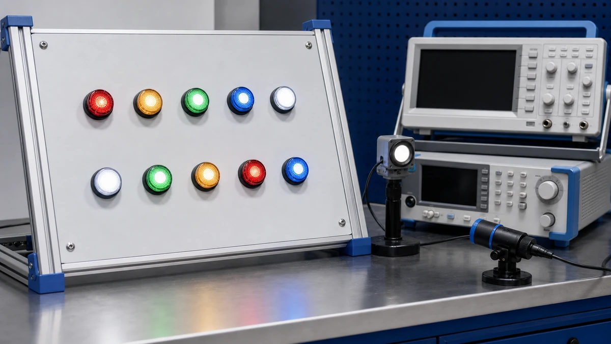
Indicator Light Voltage and Color Selection for Control Cabinets: test and measurement reference for technical selection.
Lamp Technology Comparison: LED, Incandescent, and Neon
Choosing the right lamp technology for panel indicator lights directly affects maintenance intervals, energy consumption, enclosure thermal load, and long-term reliability. In a typical industrial control cabinet, indicator lights may run continuously for thousands of hours, making lifespan and power draw critical selection parameters alongside voltage sensitivity and replacement logistics.
Technology Comparison Table
Параметр
LED
Incandescent
Neon
Typical Lifespan
50,000-100,000 hr
1,000-5,000 hr
10,000-25,000 hr
Power Draw
0.1-0.5 W per lamp
1-5 W per lamp
0.1-0.3 W per lamp
Voltage Sensitivity
Moderate — requires current limiting; sensitive to reverse polarity and overvoltage
Low — tolerates approximately plus or minus 20% without failure
Low — tolerates wide AC range
Heat Output
Very low
High — up to 80-90% of energy dissipated as heat
Very low
Replacement Cost
Low unit cost; infrequent replacement
Low unit cost; frequent replacement
Moderate unit cost; moderate interval
AC/DC Compatibility
Both — specify at ordering
Оба
AC only
Typical Voltage Range
12-240V AC/DC — model-dependent
6-250V AC/DC
110-240V AC
Selecting the Right Technology
LED indicators now dominate new panel designs. Their service life substantially reduces scheduled maintenance compared to incandescent lamps, which require replacement every 1,000-5,000 hours in continuous-duty installations. For a cabinet running 8,000 hours per year, an incandescent lamp may require annual replacement; an LED unit under the same conditions may exceed six years of continuous operation before the first replacement is needed. Confirm the exact rated service life from the product datasheet, as it varies by drive current, ambient temperature, and thermal management design.
Incandescent lamps remain in legacy systems where component interchangeability with existing sockets drives procurement decisions. Their high heat output raises the enclosure thermal load — a directly relevant concern in compact IP65 or IP67 cabinets where thermal calculations are tight. Neon indicators are limited to AC circuits and perform reliably across the 110-240V AC range, but their restricted color range and AC-only operation limit applicability in modern PLC-based control systems.
When replacing incandescent lamps with LED retrofits in existing AC circuits, verify that the LED module includes a built-in bleeder resistor. Without one, ghost voltages from capacitive coupling in long cable runs can keep the LED dimly lit even when the signal is off, creating a false indication that can mislead maintenance technicians during fault diagnosis.
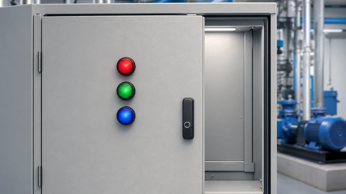
Indicator Light Voltage and Color Selection for Control Cabinets: application context reference for technical selection.
Buyer Checklist: Matching Indicator Lights to a Control Cabinet Specification
Selecting the correct indicator light voltage and color requires working through four decision points in sequence. Skipping any step risks mismatched components, failed inspections, or unreadable status signals on the panel floor.
Step 1 — Confirm Supply Voltage and Supply Type
Identify the control circuit voltage available at the indicator terminal. Common values are 24V DC, 110V AC, and 230V AC. Confirm whether the supply is AC or DC, since many LED drivers are polarity-sensitive or frequency-dependent. Measure actual voltage under load, not just nominal bus voltage. If voltage tolerance is declared as plus or minus 10% on the supply side, verify the lamp’s operating range covers the full swing including worst-case sag and spike conditions.
Step 2 — Assign Colors to Machine States
Apply the IEC 60073 color code convention as described in the previous section. Map each color to exactly one machine state before ordering. Red must not be used for any state other than a hazard or stop condition. Prepare a written color schedule as part of the electrical design documentation; this becomes part of the panel documentation package delivered to the end-user.
Step 3 — Select Mounting Format and Panel Cutout
Standard panel cutout diameters for industrial indicator lights are 16 mm, 22 mm, and 30 mm depending on the product family. Verify your enclosure panel thickness, since the indicator body nut requires a minimum and maximum sheet metal thickness to engage correctly — confirm this range from the product drawing, as it varies by series. Choose flush, projecting, or recessed lens profile based on operator visibility distance and glare requirements. For panels integrating indicator lights alongside push-button actuators, matching cutout diameters across both component types simplifies fabrication and maintains a consistent operator interface row.
Step 4 — Verify Certifications for Your Target Market
Cross-reference the required approval marks for your destination market: CE marking under the EU Machinery Directive or Low Voltage Directive for European installations, UL 508 listing for North American control panel installations, and IP65 or IP67 ingress protection rating for washdown or outdoor enclosures. Request the actual certificate document or Declaration of Conformity — a CE mark printed on the product body alone, without supporting documentation, does not confirm third-party conformity assessment. Verify that the Declaration of Conformity lists the specific harmonized standards tested against.
For panels that also include rotary switching devices, reviewing the Диапазон поворотных кулачковых переключателей Shieldhz alongside indicator light specifications helps ensure that all panel components share consistent documentation and certification packages, simplifying the panel builder’s compliance file assembly.
Step 5 — Prepare Inquiry Inputs
When submitting a sourcing inquiry, provide operating voltage and supply type, required lens color per circuit function, mounting cutout diameter, lamp type preference, quantity per panel position, required certifications, and any IP rating or custom legend requirements. Providing these inputs upfront reduces specification confirmation cycles and speeds delivery scheduling.
How Shieldhz Confirms Indicator Light Specifications Before Shipment
Specification mismatches in indicator light orders — wrong voltage range, incorrect LED color, or missing certification documentation — are among the most common causes of panel commissioning delays on the buyer side. Shieldhz, the export brand of Zhejiang Shihe Electric Co., Ltd., structures a multi-step confirmation workflow before any indicator light order enters production or shipment. This process is designed to ensure the confirmed part matches the electrical and visual requirements discussed during inquiry, and that documentation is complete before dispatch.
Zhejiang Shihe Electric Co., Ltd. has operated from its Zhejiang Province facility since 2014, with a factory floor of over 5,000 square meters, more than 100 employees, and 40 or more dedicated production machines. ISO 9001 quality management certification governs the production process; CE, RoHS, TUV, UL, UKCA, CCC, and CB certifications are available depending on product series and destination market. Certification applicability is confirmed at the inquiry stage against the declared destination market and end-use application.
Buyer Inquiry Inputs Required
Before part confirmation, Shieldhz requests the following application parameters from the buyer:
Operating voltage and supply type (AC or DC), confirmed against the AD16 series voltage range
Lens color designation (red, green, amber, blue, or white) cross-referenced against the panel functional color schedule and IEC 60073 assignment
Mounting cutout diameter and panel sheet metal thickness range
Required certification documentation: CE Declaration of Conformity, RoHS compliance certificate, or other market-specific documentation
Quantity per order, IP rating requirement if applicable, and any custom legend or marking requirement
This intake step prevents the most common sourcing error: ordering a 230V AC unit for a 24V DC control circuit, or receiving a white lens where green is operationally required. Both errors have occurred in sourcing practice when inquiries do not include explicit voltage and color confirmation.
Pre-Shipment Verification Steps
Voltage Energization Test: Each production batch is powered at rated voltage within the declared tolerance band to verify stable illumination without flickering across the LED forward voltage range.
Color Confirmation Check: Lens color is confirmed against reference samples. Amber and red lenses receive specific differentiation checks given their similar hue under standard facility lighting, which is the lens pair most frequently confused in parts handling.
Mechanical Fit Verification: Mounting thread engagement and panel cutout fit are verified against the confirmed product drawing for the specific cutout diameter ordered.
Documentation Assembly: CE Declaration of Conformity, RoHS certificate, product datasheet, and wiring diagram are bundled per shipment. Buyers can request drawing files and certificate copies before order confirmation if required for pre-approval processes.
These checks run at batch level for standard indicator light orders, not sample-only inspection. Combined panel inquiries — covering indicator lights alongside other Shieldhz control components — can be submitted as a single specification package. The Поворотный кулачковый переключатель LW28 и Поворотный кулачковый переключатель LW42 are among the rotary switching products frequently sourced alongside indicator lights for the same control cabinet build, and Shieldhz can confirm both component specifications within a single inquiry response.
For buyers who require background on relevant IEC standards applicable to their panel switching components, the IEC 60947-3:2020+AMD1:2025 standard covers switches, disconnectors, switch-disconnectors, and fuse-combination units for distribution and motor circuits, with rated voltage up to 1000V AC or 1500V DC. While IEC 60947-3 does not directly govern indicator lights, it is relevant to the switching devices that control the circuits those indicators monitor.
Indicator Light Voltage and Color Selection for Control Cabinets: supply handover reference for technical selection.
Часто задаваемые вопросы
Can I use the same indicator light body for both 24V DC and 110V AC circuits by just changing the lamp element?
No. The internal LED driver circuit is rated for a specific voltage range and supply type. Swapping only the lamp element does not change the driver’s rated insulation voltage or current-limiting design. A 24V DC driver connected to a 110V AC circuit will exceed its rated voltage within the first power cycle. Always order the voltage-rated assembly appropriate for each circuit, and confirm the voltage rating from the product datasheet before installation.
What happens if an indicator light is operated above its rated maximum voltage?
Exceeding the rated voltage stresses the LED driver and lamp insulation, causing immediate or accelerated LED failure and potential dielectric breakdown across the lamp holder. Both failure modes create safety hazards requiring panel shutdown for repair. The rated maximum voltage and the consequences of exceeding it are declared in the product datasheet; treating that value as an absolute limit, not a guideline, is the correct engineering practice.
Is IEC 60073 legally mandatory, or is it a recommendation?
IEC 60073 is referenced as a normative requirement in IEC 60204-1, the standard covering electrical equipment of machines. Compliance becomes mandatory wherever IEC 60204-1 is contractually or regulatorily required, which covers the majority of industrial equipment sold into EU, UK, and many Asia-Pacific markets. For panels not subject to machine safety standards, IEC 60073 is best practice; for those that are, it is a compliance obligation.
Why does my LED indicator light stay dimly lit even when the control signal is off?
Residual illumination on AC circuits is almost always caused by capacitive coupling in long cable runs, which feeds a ghost voltage to the LED driver even when the switching contact is open. Installing a bleeder resistor across the lamp terminals — the appropriate resistance value depends on the specific circuit impedance and should be confirmed from the lamp manufacturer’s application guidance — dissipates the stray charge and extinguishes the lamp completely when the signal is off. This issue is most common on cable runs exceeding 20 m in AC control circuits.
What panel cutout size is most common for industrial indicator lights?
The 22 mm cutout diameter is the most widely standardized format across IEC-market control panels. It aligns with the majority of push-button, selector switch, and illuminated actuator families, making mixed operator interface rows easier to specify from a single product line. The 16 mm format is common in compact panels where space is constrained. Always confirm the required cutout diameter from the product drawing before panel fabrication.
Do neon indicator lights work on DC circuits?
Standard neon indicator lights require AC voltage to sustain the ionization discharge that produces light. They are not compatible with DC circuits. For DC installations, LED-type indicators with polarity-correct wiring are the correct choice. Neon types are applicable to AC circuits in the 110-240V range and remain in use in older installation types where their simplicity and AC compatibility are valued.
How do I confirm that an indicator light is genuinely CE-marked rather than self-declared?
Request the Declaration of Conformity document listing the specific harmonized standards the product was tested against, the notified body involvement if applicable, and the manufacturer’s legal entity and address. A CE mark printed or molded on the product body alone does not confirm third-party conformity assessment. For indicator lights, the relevant harmonized standards typically include the Low Voltage Directive and the Electromagnetic Compatibility Directive; confirm the specific directives covered in the Declaration of Conformity match your application’s compliance requirements before accepting the documentation as sufficient.
Ши, Мукси
Ши, Мукси пишет технические статьи Shieldhz для покупателей промышленных систем управления и электрических компонентов, охватывая поворотные кулачковые переключатели, разъединители, PV DC разъединители, кнопки, индикаторные лампы, водонепроницаемые корпуса и клеммные блоки. Статьи основаны на опыте производства и экспорта компании Zhejiang Shihe Electric Co., Ltd., с практическим акцентом на выборе модели, технических характеристиках, чертежах, сертификации, рейтингах IP и деталях запроса, которые покупатели должны подтвердить перед заказом.