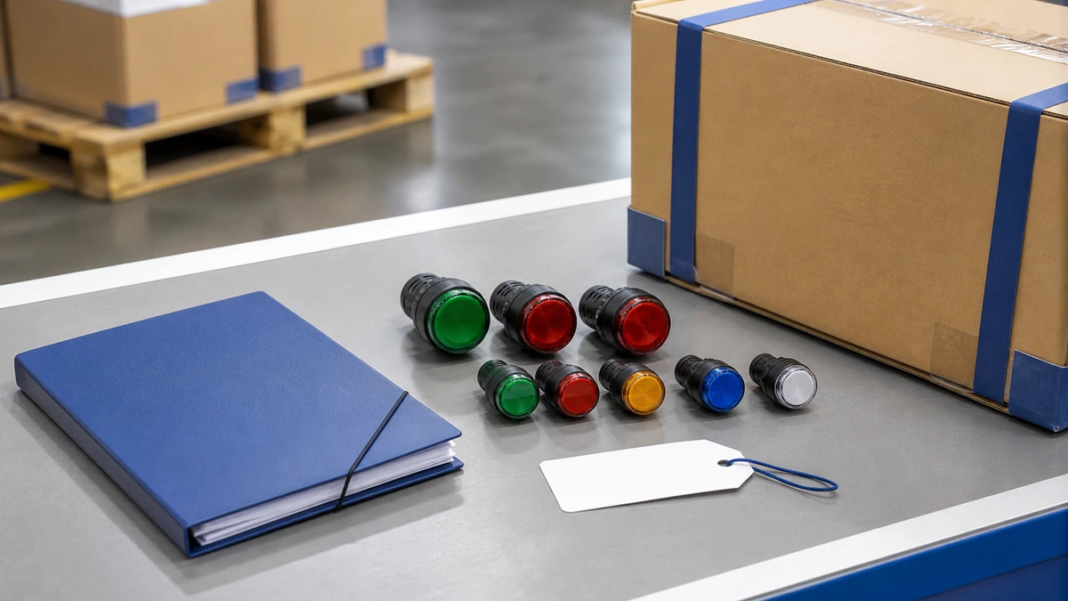
16mm vs 22mm Panel Indicator Lights: Cutout and Application Selection
Use a practical buyer checklist to evaluate 16mm vs 22mm indicator light inputs, documentation, approval controls and the exact push button, selector switch or emergency-stop operator route.
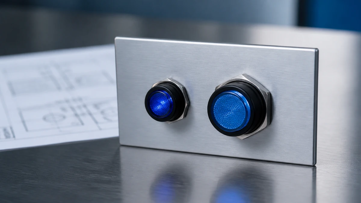
For most panel builds, the 16mm vs 22mm indicator light decision is not only a hole-size choice. It affects the mounting family, rear clearance, wiring access, front-panel visibility, legend space and how consistently the pilot light matches nearby operators.
Choose 16mm when panel density, compact enclosures and close device spacing are the main constraints, subject to the exact model drawing.
Choose 22mm when visibility, glove-friendly layout spacing, common operator family matching or larger legend areas are more important.
Before quotation, confirm cutout, panel thickness, rear depth, voltage, lens color, environment and documentation requirements against the current drawing and datasheet.
What the 16mm vs 22mm choice actually decides
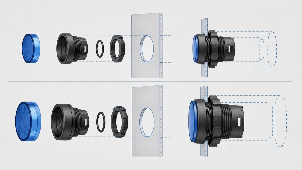
The cutout size selects a mounting family, not just a lamp diameter. A 16mm indicator and a 22mm indicator can differ in bezel size, rear body depth, retaining method, lamp module arrangement, wiring access and accessory compatibility.
An exact drawing identifies the interfaces that must be controlled for the approved model route.
Mounting family comes first
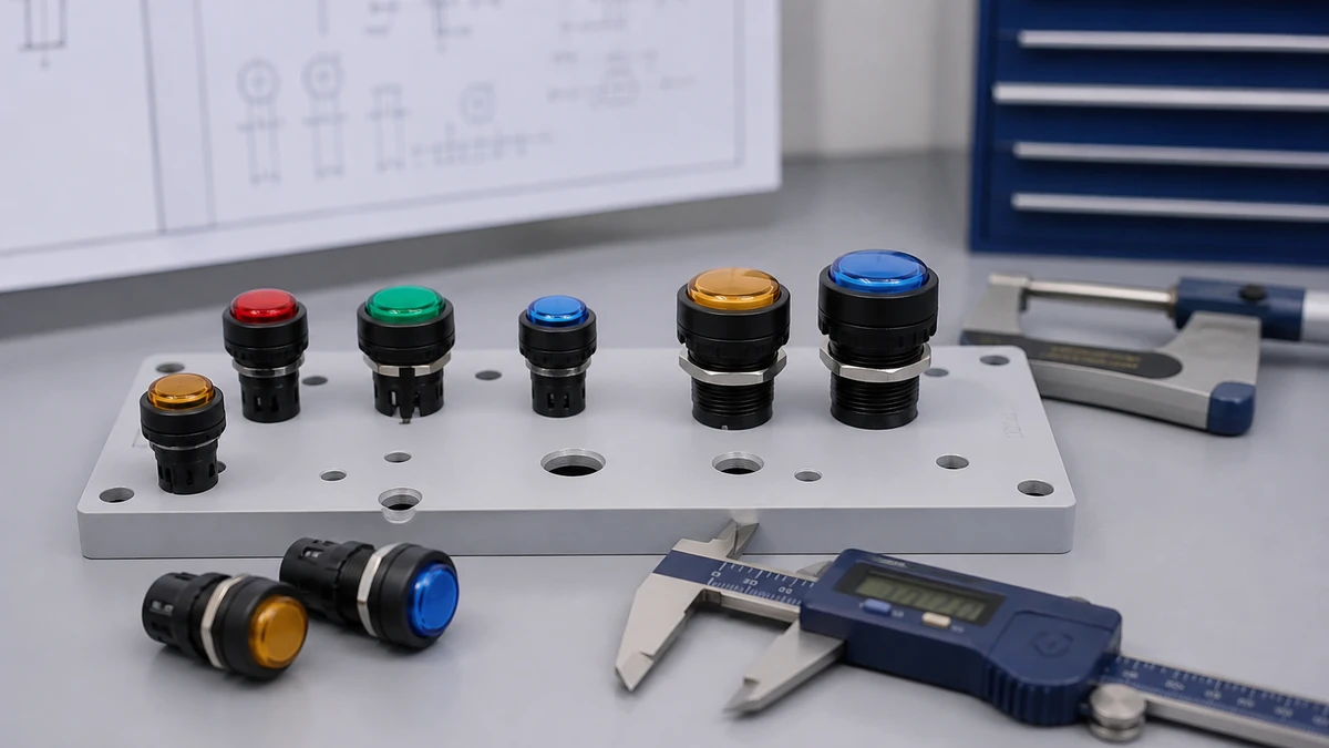
Machine builders often standardize one panel family so indicators, push buttons and selector switches look consistent. If the panel already uses a 22mm operator family, a 22mm indicator may reduce mixed hardware and simplify panel drawings. If the machine has a compact local box, a 16mm indicator may fit where a larger family would force a wider enclosure.
Use the exact product drawing for the hole diameter, anti-rotation feature if present, panel thickness range and retaining hardware. Do not rely only on the nominal 16mm or 22mm label.
When 16mm is usually investigated
A 16mm route is commonly investigated when the buyer needs compact status indication on small panels, local sensor boxes, compact machine modules or dense control surfaces. The commercial question is whether the smaller front face still gives enough visibility and whether the rear body leaves enough wiring access.
For distributor stock planning, 16mm indicators may serve applications where space is a stronger buying factor than operator-family uniformity. Final suitability remains exact-model and buyer-application dependent.
When 22mm is usually investigated
A 22mm route is commonly investigated when a panel uses a standard operator layout with adjacent push buttons, selector switches or emergency-stop operators. The larger front presence can also help when operators view the panel from farther away or in busy machine areas.
For a broader product-family view, use the Shieldhz push button and indicator light range as a starting point, then confirm the specific indicator model drawing before releasing the panel cutout.
Cutout, spacing and panel layout comparison
The right cutout is the one that fits the approved drawing, panel process and service access. Nominal size helps shortlist the family, but the fabrication release should use the exact cutout dimensions and tolerances from current documentation.
Cutout decision table
Buyer decision
16mm indicator light route
22mm indicator light route
What to confirm before release
Panel hole size
Smaller nominal mounting family
Larger nominal mounting family
Exact cutout diameter, tolerance and any keyway detail
Front-panel density
Better for tight rows or compact boxes
Needs more faceplate area
Center-to-center spacing on the final layout
Matching nearby operators
May look different if the panel uses 22mm operators
Often easier to match a 22mm operator family
Bezel style, color, lens shape and series compatibility
Engraving or legend area
More limited around each device
More room for legends or labels
Legend plate size, text height and language requirements
Retrofit risk
May require adapter or new panel work if replacing another size
May not fit a compact existing panel
Existing hole, burr condition, panel thickness and available rear space
Panel drawing checklist
Before approving the panel drawing, confirm:
Exact cutout diameter and tolerance from the indicator drawing.
Panel thickness range for the selected model.
Minimum center spacing required for tools, fingers and wiring.
Front bezel diameter, lens height and clearance from door edges.
Rear-body envelope with cable bend radius or wiring route.
Label, legend or nameplate area around the device.
Whether painted, stainless, plastic or coated panels affect mounting details.
Rear clearance and wiring access
Rear clearance can decide the selection even when both sizes fit the front panel. A 16mm front may still have a rear body that conflicts with enclosure depth, while a 22mm family may offer more working room between adjacent devices but require more panel area.
Sample review should connect the exact item to its current drawing and requested evidence package.
Depth behind the door
Check the full installed depth from the panel surface to the rear of the lamp body, including any wiring, plug, resistor module or connector arrangement supplied with the exact model. Also check door swing clearance if the device is mounted on an enclosure door.
For shallow junction boxes, a few millimeters can decide whether the door closes without stressing wires. For dense control cabinets, side clearance between neighboring devices may be as important as total rear depth.
Wiring access and maintenance
Maintenance teams need enough room to identify wires, test circuits and replace parts if the selected design allows replacement. A compact 16mm route can save panel space but may make rear access tighter in high-density rows.
When the indicator is part of a larger control-station layout, review adjacent devices at the same time. For foundational operator concepts outside this indicator-light decision, see the push button switch basics.
Rear-clearance action list
For each candidate model, ask for or verify:
Installed rear depth from the mounting surface.
Rear body diameter or envelope.
Wiring entry direction and required bend space.
Clearance to enclosure door hardware, ducts and adjacent devices.
Service tool access for the retaining nut or mounting hardware.
Whether the selected model uses integral leads, screw connection or another exact-model connection method.
Visibility, lens color and operator recognition
Choose the size that gives the required recognition distance and panel clarity for the machine location. The larger family can make status indication easier to see, while the smaller family can keep compact equipment readable when the operator stands close to the panel.
Viewing distance and panel density
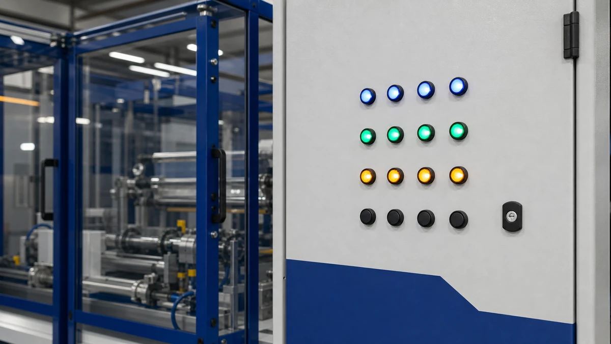
A compact equipment panel viewed at arm’s length may not need a large front indicator. A production-line panel viewed across a guarded area, from a walkway or under mixed lighting may benefit from a larger lens and more separation between statuses.
Avoid deciding only from catalogue images. Print the panel layout at scale or review a physical sample when visibility is important to the buyer.
Color and status discipline
Lens color should match the machine builder’s status convention, buyer specification and destination-market expectations. The same color can carry different meaning depending on the plant standard, so confirm the legend and function together.
Status-design question
Commercial risk if missed
Confirmation method
What machine condition is being indicated?
Wrong color or wording can confuse operators
Buyer function list or electrical design note
Who views the indicator and from where?
Lens may be too small or too close to other devices
Scaled layout review or sample check
Is the panel used in bright, dusty or wet areas?
Visibility and service life expectations may be misaligned
Exact environment statement and datasheet review
Is multilingual marking required?
Legend space may be insufficient
Approved artwork or label specification
Are similar colors grouped together?
Operators may misread status at a glance
Panel layout review before drilling
Visibility checklist for buyers
Use this checklist before choosing the final family:
Viewing distance: close local panel, machine-side station or larger line panel.
Ambient light: indoor panel, bright work area or low-light location.
Number of indicators: single status, grouped alarms or dense process display.
Lens style: flat, raised or other exact-model option.
Service expectation: easy recognition during troubleshooting or only local confirmation.
Electrical selection: voltage, lamp type and contact context
The electrical route must match the control circuit and exact indicator model. A 16mm or 22mm front size does not by itself determine voltage, current, lamp technology or permissible connection arrangement.
Installation conditions change the product-route and document questions a buyer must resolve.
Voltage and current are model-specific
Confirm the control voltage, AC or DC supply, expected current and wiring method before requesting quotation. Also verify whether the lamp is integral, replaceable or supplied as a specific module for the selected family.
Do not assume that two indicators with the same front size share the same electrical data. The datasheet and model code are the evidence for voltage range, current, polarity requirements if applicable and any limitations.
Indicator lights versus control contacts
Panel indicators provide status indication. They should not be treated as the switching contact arrangement for a control command unless the exact selected product is a combined illuminated operator and the circuit design supports that use.
If the panel includes push-button or selector circuits near the indicator, specify contact logic separately from the pilot light. The Shieldhz NO and NC contact guide explains contact arrangement terminology without replacing the need for the exact drawing and circuit review.
Electrical confirmation checklist
Provide these details in the RFQ or technical review:
Indicator function, such as power, run, fault, trip signal or mode status.
Rated control voltage required by the buyer’s circuit.
AC or DC supply and any polarity requirement.
Lens color and whether illumination must be continuous or signal-driven.
Wiring method expected by the panel builder.
Model-specific electrical datasheet required for approval.
Destination-market documentation or certificate request, if applicable.
Environment, materials and documentation boundaries
Environmental and compliance decisions are exact-model and destination-market dependent. The same nominal 16mm or 22mm family can include different materials, sealing structures, lens options or documentation packages depending on the selected item.
Enclosure and site conditions
Confirm whether the device is installed indoors, outdoors, on a machine door, on a pendant station or in a washdown-prone area. Also confirm exposure to oil mist, coolant, dust, UV, cleaning chemicals, vibration or temperature extremes.
IP class, material suitability and environmental claims must come from the current datasheet, drawing or certificate for the exact model. They should not be inferred from cutout size alone.
Standards and certificates
For control-circuit devices, the IEC 60947-5-1 listing is useful context because the IEC catalogue describes the subject area and notes that a more recent edition exists. That catalogue listing should not be treated as a universal product-certification claim for every indicator light, size or configuration.
Ask for the documentation package needed for the destination market and buyer approval process. Depending on the project, that may include a datasheet, dimensional drawing, material information, certificate copy or declaration linked to the exact model.
Choosing indicator lights beside push buttons, selectors and emergency-stop operators
When indicators sit beside operators, choose a mounting family that supports a clear, maintainable control layout. The indicator-light decision should be made with adjacent operator spacing and labeling in view, but it should not become a mixed cutout guide for every device type.
Documentation control, sample acceptance and protective packing are separate handover checks.
Layout consistency near operators
A panel that combines pilot lights, momentary push buttons and selector switches often benefits from a consistent visual family. However, a compact auxiliary panel may intentionally use 16mm indicators beside larger operators if space and visibility support that decision.
For mixed panels, keep status indication and command input visually distinct. Use lens color, label position and spacing to reduce confusion during operation and maintenance.
Emergency-stop proximity and safety boundary
Emergency-stop operators require special layout attention, but selecting an operator does not validate a complete machine safety function. The complete safety function depends on risk assessment, circuit architecture, components, wiring, diagnostics, validation and applicable requirements for the machine and destination market.
For panel-layout context around emergency-stop and selector placement, refer to the emergency-stop and selector layout guide. Use that as layout guidance, not as a substitute for safety validation of the complete machine.
Mixed-panel action list
For panels with indicators and operators, confirm:
Which devices are status indicators and which are command operators.
Whether the panel standard uses one mounting family or mixed sizes.
Center spacing between indicators, push buttons and selectors.
Label priority: machine function first, model code second.
Emergency-stop location, guard clearance and visibility.
Documentation for each exact device, not only the panel family.
Accessory, marking and service decisions
Accessory planning should follow the selected indicator family. Legend plates, bezels, lamp modules and mounting hardware can vary by series, so they should be confirmed by exact model rather than by nominal cutout alone.
Legend plates and markings
A 22mm family may offer more physical space around the device for labels, but actual legend options depend on the series. A 16mm family may still work well where the panel has printed graphics or a separate nameplate area.
For accessory context across operators and pilot devices, use the Shieldhz contact block and legend plate guide. Then confirm which plates, markings or lamp parts apply to the selected indicator model.
Service and spare planning
Maintenance planners should decide whether they want one common indicator family across machines or different sizes by enclosure type. Standardization can simplify drawings and spare identification, while mixed sizing may reduce enclosure cost or improve usability in specific locations.
Record the exact model code, voltage, lens color and drawing revision in the panel documentation. Avoid describing spares only as “16mm red light” or “22mm green light,” because that may not identify the electrical or mechanical configuration.
Spare-identification checklist
For maintenance and procurement, list:
Full model code.
Cutout size and drawing number.
Lens color and lens style.
Control voltage and AC/DC requirement.
Connection method.
Accessory or legend details.
Documentation revision used for approval.
How Shieldhz confirms a push button, selector switch or emergency-stop operator route
Shieldhz confirms the route by matching the buyer’s application inputs to current product documentation before quotation or final selection. Final suitability is confirmed against the current drawing, datasheet, certificate package and the buyer’s application.
Pre-quotation confirmation inputs
For a push button, selector switch or emergency-stop operator route, Shieldhz checks the machine function and destination market first. Then the review moves to operator action, control voltage and current, contact arrangement, panel cutout and mounting, environment, marking or legend requirements, and the exact documentation package needed by the buyer.
This process also helps when indicator lights share a panel family with operators. It prevents the cutout decision from being separated from rear clearance, legend space and documentation requirements.
Documentation package for approval
The quotation route should identify which exact drawing, datasheet and certificate package the buyer needs. Some buyers need only dimensional and electrical confirmation, while others need destination-market documentation before purchasing.
For combined layouts, contact blocks, lamp modules and legend accessories must be checked by selected series and model. Final suitability is not confirmed by catalogue family name alone; it is confirmed against current product documentation and the buyer’s application.
Conclusion
The 16mm vs 22mm indicator light decision is a practical mounting-family choice. A 16mm indicator can help compact panels, while a 22mm indicator can improve visibility, spacing and consistency with common operator layouts.
For commercial and engineering selection, do not stop at the nominal cutout. Confirm the exact drawing, rear clearance, voltage, lens color, environmental conditions, marking requirements and documentation package before releasing the panel or purchase order.
Frequently Asked Questions
Is a 16mm indicator light always smaller behind the panel?
Not always. The front cutout is smaller, but rear depth, wiring direction and body shape depend on the exact model. Always check the dimensional drawing before approving a compact enclosure.
Can I replace a 16mm indicator with a 22mm indicator in the same panel?
Usually this requires panel modification because the nominal cutout is different. Before retrofit, confirm the existing hole, panel thickness, available front spacing and rear clearance.
Is 22mm better than 16mm for visibility?
A 22mm family may provide a larger front presence, but visibility depends on lens design, color, brightness, viewing distance, ambient light and panel layout. Confirm the specific model and application conditions.
Does the cutout size determine the voltage rating?
No. Voltage and current are model-specific electrical characteristics. The correct voltage must be selected from the datasheet and model code for the buyer’s control circuit.
Should indicator lights match the push-button size on the same panel?
Matching sizes can improve visual consistency and simplify panel standards, but it is not mandatory for every application. Compact panels may use mixed sizes if spacing, visibility and service access are acceptable.
Does choosing an emergency-stop operator complete the machine safety function?
No. Selecting an emergency-stop operator is only one component decision. The complete machine safety function must be designed and validated according to the machine risk assessment, circuit architecture, documentation and applicable destination-market requirements.
Shi, Muxi
Shi, Muxi writes Shieldhz technical articles for industrial control and electrical component buyers, covering rotary cam switches, isolator switches, PV DC disconnects, push buttons, indicator lights, waterproof enclosures, and terminal blocks. The articles are based on Zhejiang Shihe Electric Co., Ltd.'s manufacturing and export experience, with practical emphasis on model selection, datasheets, drawings, certifications, IP ratings, and inquiry details buyers should confirm before ordering.