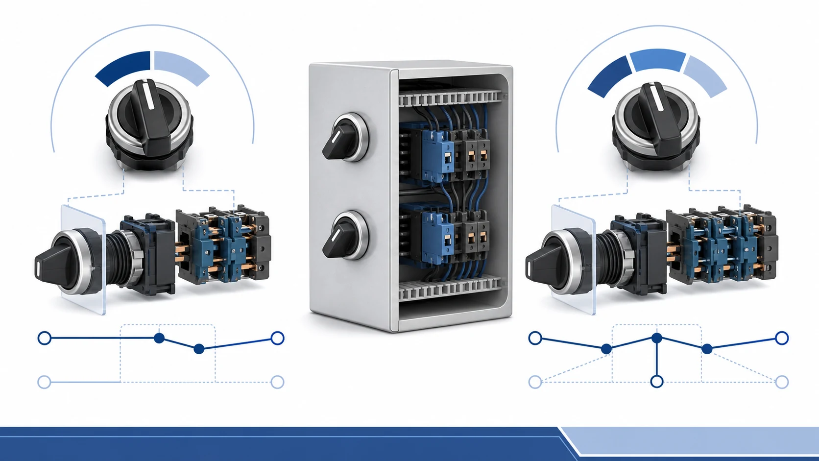
A two-position selector switch is the better choice when an operator only needs two stable control states. A three-position selector switch is the better choice when the circuit needs a third deliberate state, such as a centre OFF position, HAND-OFF-AUTO, or FORWARD-OFF-REVERSE. The number on the operator is not the whole specification: the panel schematic, contact programme, return action, legend plate, and device rating must all agree.
Start with the control states, not the handle shape
Panel builders often begin with the visible operator: two handle positions or three. That is a useful first filter, but the more reliable starting point is the state sequence required by the machine or process. Write the sequence in plain language before selecting a device. Examples include ON/OFF, LOCAL/REMOTE, HAND/OFF/AUTO, and FORWARD/OFF/REVERSE. That sequence tells the designer how many maintained states are needed and whether a centre position must provide a safe neutral state.
A two-position selector normally suits a simple maintained choice. It can select one of two control paths, enable or disable a permissive, or choose local versus remote control. A three-position selector adds one further defined state. In many panel designs that extra state is not a convenience; it is how the circuit avoids moving directly between two active commands. For example, a HAND/OFF/AUTO selector gives the operator an intentional non-command state between manual and automatic operation.
Choose the operator state sequence before selecting the selector-switch configuration.
Do not assume that every three-position unit has centre OFF, or that every two-position unit is maintained. The position sequence and return action are model and contact-programme dependent. The product drawing and switching table are the controlling documents. If the circuit has a safety, interlock, or PLC input consequence, confirm the required state against the approved schematic rather than relying on a generic catalogue image.
Compare the two options at panel level
Selection question
2-position selector switch
3-position selector switch
Stable operating states
Two states, such as ON/OFF or LOCAL/REMOTE.
Three states, such as HAND/OFF/AUTO or FORWARD/OFF/REVERSE.
Centre neutral state
Not available as a third maintained state.
Available when the selected contact programme and operator legend specify it.
Typical panel role
Mode choice, enable/disable, simple source or signal selection.
Mode selection with an OFF or neutral condition, directional control, test/normal/reset routes.
Contact review
Confirm the two-state NO/NC pattern and any spring return.
Confirm each position separately; centre and end positions can use different contact states.
Operator labelling
Two clear legends are normally enough.
All three legends must match the drawing and the real contact sequence.
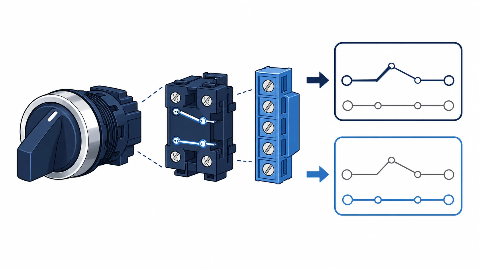
The table is a specification aid, not a universal wiring diagram. The same operator style can be assembled with different contact blocks. A panel that needs an indicator, a relay permissive, and a PLC input may require more than one contact element even though the front of the device only shows two or three positions. Review the switching table alongside the circuit diagram before the bill of materials is released.
Contact programme and return action decide the real function
The front legend describes what an operator sees. The contact programme describes what the circuit receives. This distinction matters most when replacing an existing selector or when a panel uses multiple control voltages. A two-position LOCAL/REMOTE switch, for example, may transfer one control signal while opening another. A three-position HAND/OFF/AUTO switch may maintain one path at each end position and open both at centre. Those are different electrical behaviours even if the operators look similar.
Start by identifying whether the handle must remain in the selected position or return after release. Maintained selectors are common for mode and source choices. Spring-return selectors are common where an operator makes a momentary command, such as a jog, reset, or test action. A three-position spring-return unit can also have different return behaviour from each side. That must be specified in the contact programme and operator description, not inferred from the position count.
The switching table and schematic establish the required contact programme.
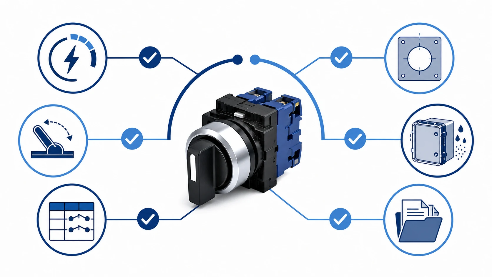
For a control-panel design, collect these inputs before choosing the selector: control voltage, load or signal being controlled, required positions, maintained or spring-return action, number of NO and NC paths, legend text, panel cutout, enclosure environment, and any document or certification requirement. The NO and NC contact basics are useful background, but a selector-switch order should always be checked against the application-specific drawing.
Use application logic to choose the position count
ON/OFF and LOCAL/REMOTE
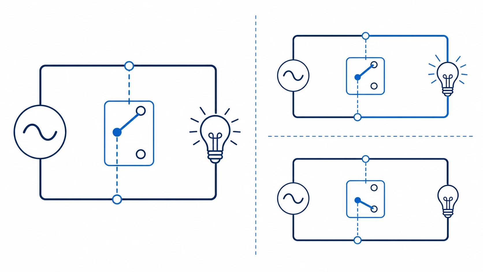
Two positions are usually enough when the operator has only two valid choices. ON/OFF can suit a simple enable function when the circuit design provides the necessary protection and interlocking elsewhere. LOCAL/REMOTE is another common two-state use: the operator selects whether a command originates at the panel or from a remote system. The selector itself does not make the control scheme safe; its contact arrangement must be coordinated with the circuit design.
HAND/OFF/AUTO
Three positions are appropriate when manual control, an intentional OFF state, and automatic control must be visibly separate. In a pump or ventilation panel, the centre OFF state can prevent an unwanted command while maintenance or commissioning work is being completed. The designer should still define how downstream contactors, overload devices, safety circuits, and PLC logic respond in every position.
FORWARD/OFF/REVERSE
A three-position operator is also common for directional commands when the design needs a clear neutral state. Never treat the selector as the entire reversing solution. The circuit must use suitable interlocking and the motor-control design must prevent conflicting commands. The selector is only one input to that system. For broader operating examples, see selector switch applications for operator interfaces.
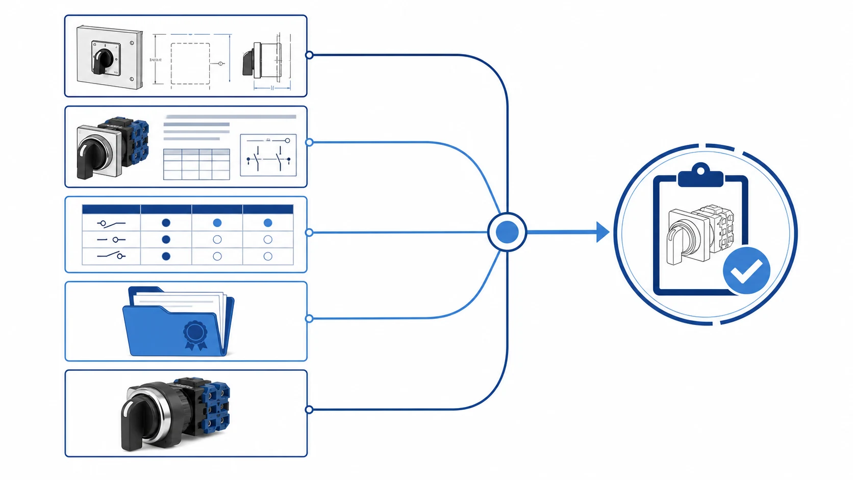
Check the required sequence, contact programme, legend, and mounting details together.
Avoid the replacement mistakes that create commissioning delays
The most common mistake is replacing a three-position operator with a two-position version because the mounting hole is the same. That can remove the centre OFF state or collapse two distinct commands into one. The opposite error is installing a three-position unit when the drawing only expects two control states, leaving an unused or confusing position on the panel.
Another frequent problem is a mismatch between the legend plate and the contact programme. A handle marked AUTO/OFF/MANUAL is not acceptable if the wired contact sequence does not match those labels. During commissioning, check the legend, the operator movement, and the contact state at each position. Record the confirmed configuration in the panel documentation so future replacements use the correct model and contact blocks.
Environmental details also matter. A device suitable for a protected indoor door may not be appropriate for washdown, outdoor, vibration, or high-dust use without the correct enclosure and sealing arrangement. Mounting size, bezel style, lamp modules, and contact-block geometry should be confirmed from the model drawing. The applicable product documentation and the relevant control-device requirements, including IEC 60947-5-1, should guide the final specification.
How Shieldhz confirms a selector-switch configuration
For a Shieldhz selector-switch enquiry, send the panel schematic or the intended sequence first, then provide the control voltage, required legend, handle action, panel cutout, contact requirements, enclosure condition, and any requested documents. Shieldhz can use those inputs to confirm the model route, contact-block combination, drawing, and available documentation package before an order is released. This is more dependable than ordering from a photograph alone.
A clear enquiry includes the control sequence, contact needs, legend, and mounting details.
For modular 22 mm operator arrangements, start with the Shieldhz push-button and indicator-light range and then check the relevant series drawing. Metal operator formats, LED options, and sealing requirements can follow a different configuration route. Ask for the current datasheet, dimensional drawing, and certificate availability for the exact model rather than treating one family description as a universal specification.
Frequently asked questions
Is a three-position selector switch always better?
No. It is better only when the control logic needs three deliberate operator states. A two-position device is clearer and more appropriate for a genuine two-state function.
Can a two-position selector replace a three-position selector?
Only after reviewing the approved schematic and the existing switching table. A replacement can remove a centre OFF state, a mode selection, or a required contact path.
Does three-position always mean centre OFF?
No. Centre behaviour, maintained action, and contact state depend on the chosen model and contact programme. Confirm them in the drawing and datasheet.
How many contact blocks are needed?
The number depends on the circuit paths required at each position. Count relay, indicator, PLC, and interlock signals from the schematic rather than choosing by handle style.
Should I specify the legend plate separately?
Yes. State the exact legend text and position order so the operator label, panel drawing, and actual contact sequence remain aligned.
What should be included in a selector-switch RFQ?
Include the application, voltage, required positions, return action, contact programme, legend, mounting cutout, enclosure condition, required drawing, and any certificate request.
Request a selector-switch configuration review
Send the control sequence and panel drawing to Shieldhz with the required positions, contacts, legend, and environmental conditions. The response can be matched to the appropriate model route, contact arrangement, dimensions, and available documentation for the exact configuration.
Shi, Muxi
Shi, Muxi writes Shieldhz technical articles for industrial control and electrical component buyers, covering rotary cam switches, isolator switches, PV DC disconnects, push buttons, indicator lights, waterproof enclosures, and terminal blocks. The articles are based on Zhejiang Shihe Electric Co., Ltd.'s manufacturing and export experience, with practical emphasis on model selection, datasheets, drawings, certifications, IP ratings, and inquiry details buyers should confirm before ordering.