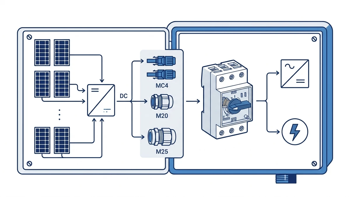
For most rooftop and ground-mount PV installations, MC4 cable entry suits pre-terminated solar cables up to 6 mm2, while M20 or M25 threaded gland entries suit field-wired runs where cable diameter, conduit routing, or local wiring codes require a standard gland termination. Your choice depends on cable type, installation method, and compliance requirements. Specifying the wrong entry type at the order stage means replacing the enclosure body, not just swapping a fitting. This guide walks through sealing architecture, cable compatibility, installation procedure, applicable standards, and the eight specification inputs that determine which entry format belongs on your purchase order.
What MC4 Entry Delivers
MC4 connectors are push-fit terminations standardized for 4 mm2 and 6 mm2 single-core PV cables with outer diameters typically between 5.5 mm and 8.0 mm. Because the connector body engages a mating socket on the isolator housing, the installer achieves IP67 ingress protection per IEC 60529 at the cable entry point without fitting a separate gland. On a rooftop array where factory-terminated MC4 leads run from the string combiner to the GF40 PV DC isolator switch, this eliminates the need to size, insert, and torque individual gland nuts at each unit, a measurable time saving when dozens of isolators are mounted in sequence.
The tradeoff is inflexibility. MC4 entry is committed to MC4-compatible cable and cannot accept armoured cable, conduit terminations, or site-crimped conductors larger than the rated range without an adapter. Adapters introduce an additional potential ingress point and should be avoided wherever the native entry format can be specified correctly from the outset.
What M20 and M25 Gland Entry Delivers
M20 and M25 knockouts or pre-tapped entries accept a wide range of cable gland types, including nylon, brass, or stainless steel, rated from IP54 to IP68 depending on gland selection and housing interface. This makes M20 or M25 entries the preferred route when the DC wiring uses armoured cable, when the installation authority requires conduit entry, or when cable diameters fall outside MC4 compatibility. M25 entries can typically accommodate cables up to approximately 17 mm to 18 mm outer diameter, supporting heavier multi-core or armoured runs used in commercial PV array DC circuits.
Unlike MC4, the gland compression-nut design allows the installer to terminate virtually any cable OD within the gland’s rated range using the same enclosure entry point. Sealing quality is directly proportional to applied torque, which introduces installer-dependent variability that MC4 geometry avoids.
How MC4 and M20 M25 Entries Differ in Sealing Architecture
MC4 Integrated Sealing
MC4 connectors use a push-lock bayonet coupling with an integrated EPDM or silicone O-ring compressed radially against the mating socket. The geometry is self-aligning and polarity-keyed, which prevents cross-connection between positive and negative conductors. Sealing action does not depend on installer torque, reducing variability in the field. The bayonet lock also resists loosening under mechanical vibration without supplementary fastening.
M20 and M25 Compression Gland Sealing
Tightening the locknut deforms a conical elastomer insert radially inward around the cable jacket. Sealing quality is proportional to applied torque. Under-tightening produces an incomplete seal, while over-tightening can crack the insert or damage the cable jacket. A correctly torqued M20 gland typically accommodates cable outer diameters from 6 mm to 12 mm; M25 extends that range to approximately 9 mm to 17 mm, providing flexibility for multi-core or armoured solar cables. Compression-nut glands can gradually back off under sustained vibration or thermal cycling unless a secondary locking feature or torque-indicator paint mark is applied after final tightening.
Comparative Specification Table
Do not treat the table as a universal rating sheet. Cable diameter range, gland thread, connector family, IP rating, torque range, and regional compliance must be confirmed from the current Shieldhz drawing, datasheet, and certificate package for the exact configuration.
Parameter
MC4 Entry
M20 Gland
M25 Gland
IP rating (IEC 60529)
Up to IP67
Up to IP68 (gland-dependent)
Up to IP68 (gland-dependent)
Compatible cable OD
~5.5 mm to 8.0 mm
~6 mm to 12 mm
~9 mm to 17 mm
Locking mechanism
Push-lock bayonet
Compression nut
Compression nut
Vibration resistance
High, keyed and tool-release
Moderate, torque-dependent
Moderate, torque-dependent
Installation tool
MC4 locking tool
Spanner wrench
Spanner wrench
Rewire flexibility
Low
High
High
For installations demanding IP67 or higher at the entry point, M20 or M25 glands with an appropriately rated gland body can meet or exceed the threshold that MC4 provides, provided the correct gland is selected and torqued to the manufacturer’s specification. Confirm the declared IP rating against the chosen entry method on the isolator enclosure drawing before installation.
Matching Cable Entry Type to PV System Cable Configurations
Sealing architecture sets the performance ceiling for each entry type. The cable schedule on your specific project determines which ceiling you actually need.
Decision Matrix
Cable Type
Outer Diameter
Installation Scenario
Recommended Entry
Rationale
Single-core PV wire
4 mm2 to 6 mm2
Residential rooftop, single string
MC4 integrated entry
Direct plug-in, no gland selection or torque required
Single-core PV wire
4 mm2 to 6 mm2
Multi-string residential or commercial
MC4 integrated entry
Consistent connector interface across all string runs
MC4 connectors are absent; gland provides IEC 60529-compliant sealing for existing cable
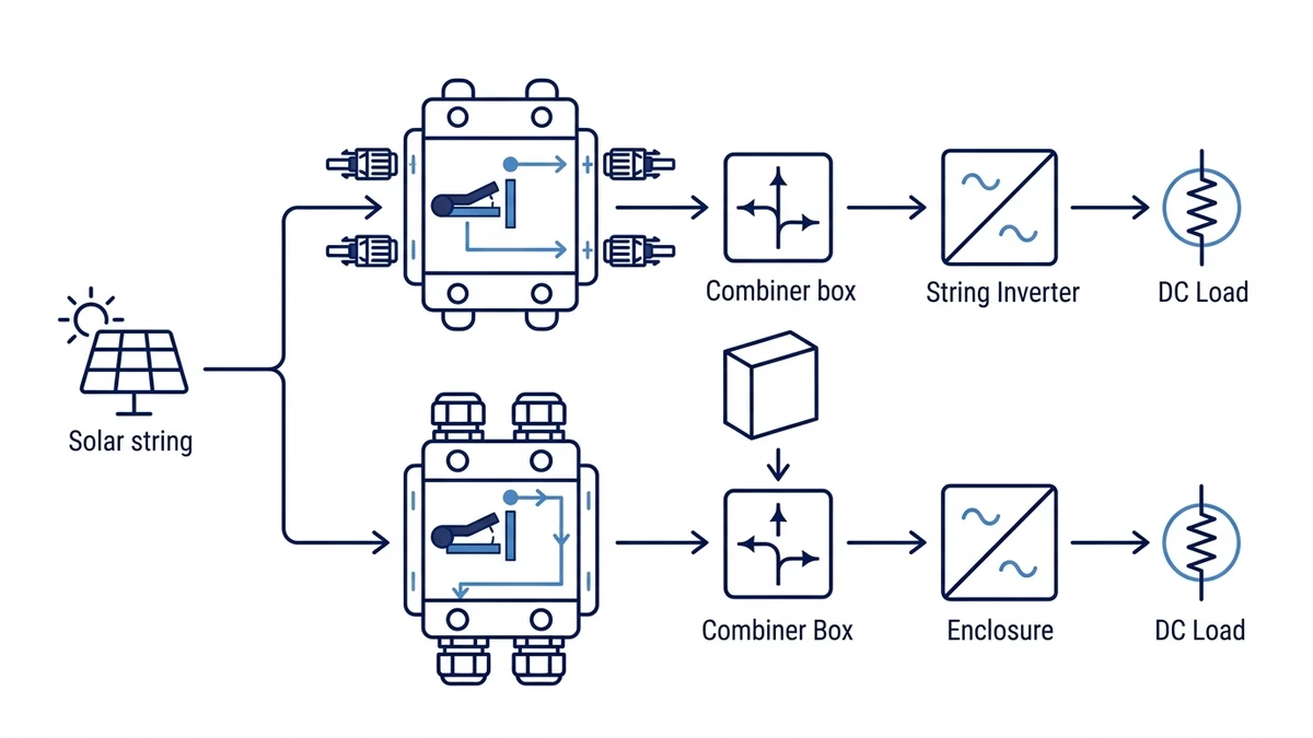
In a typical commercial rooftop installation where 6 mm2 single-core PV wire terminates directly at a GF40 series DC isolator, MC4 integrated entries eliminate the gland selection step entirely, reducing assembly time and the risk of under-torqued seals. For ground-mount systems running armoured cable from combiner boxes, M25 entries on an enclosure-mounted isolator from the Shieldhz DC isolator switch range provide the mechanical grip and IP integrity that MC4 connectors cannot offer.
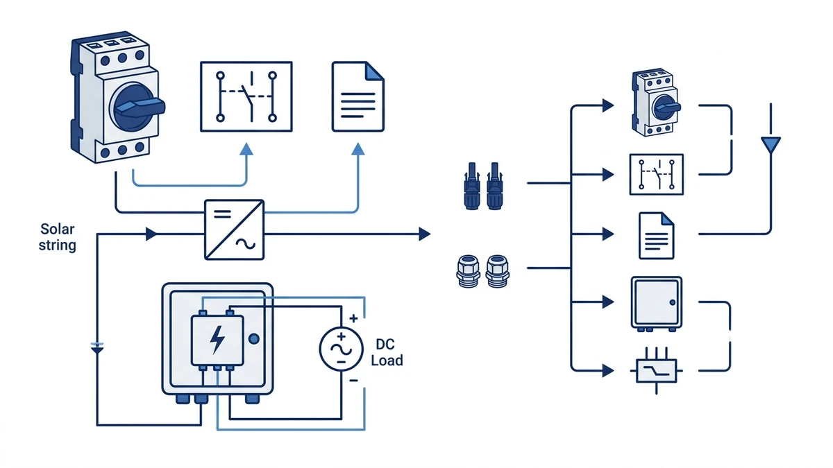
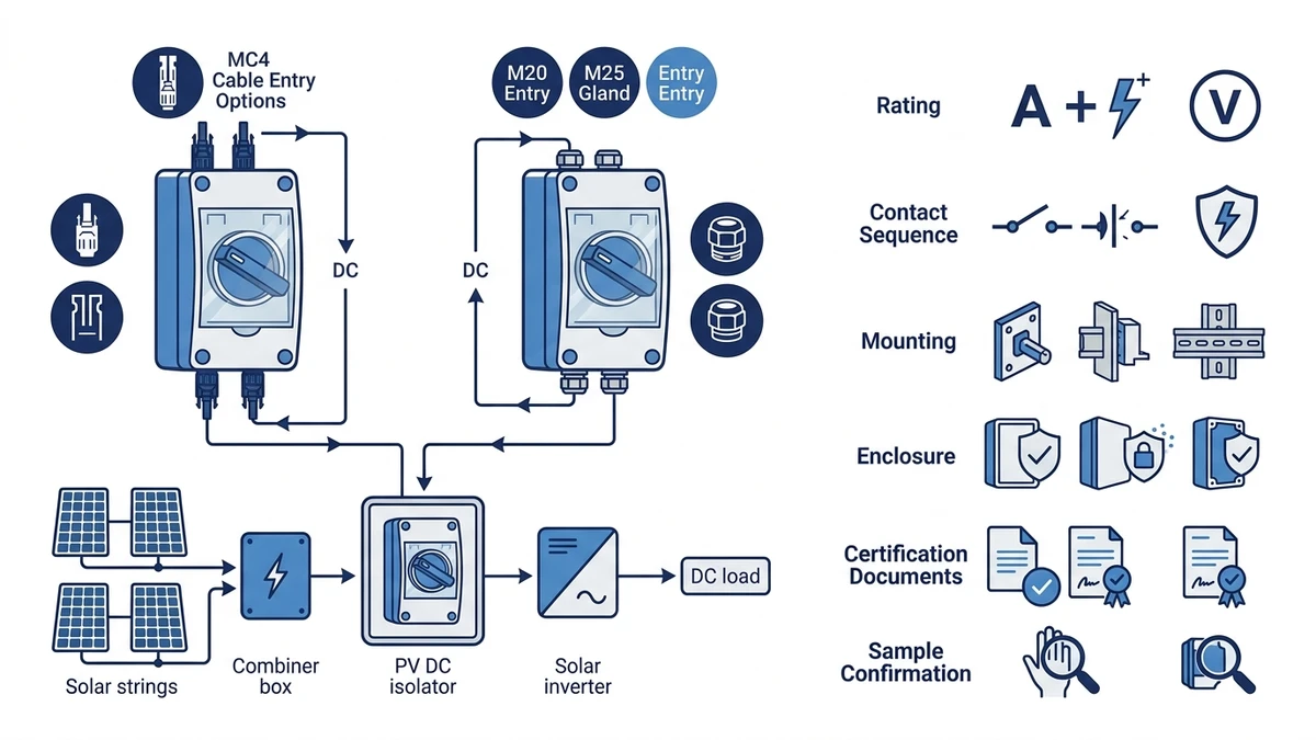
Figure 2. Selection checks should connect DC voltage, string current, pole count, enclosure, cable entry, and documentation.
Qualified Installer Checks for MC4 vs M20 M25 Entries
Getting the entry type right on paper still leaves room for sealing failures if field procedure is not followed precisely. The two entry types fail in entirely different ways when shortcuts are taken.
Safety boundary: This section is not a field wiring tutorial. Cable entry installation, connector mating, gland tightening, and PV DC checks should be completed by qualified installers using the project method statement, lockout/tagout procedure, and the manufacturer drawings for the exact isolator and cable set.
MC4 Integrated Entry: Installer Checklist
Confirm cable OD — verify that the PV cable OD sits within the connector’s rated insertion range. Confirm exact limits against the datasheet.
Inspect the O-ring — check the moulded elastomer face-seal for cuts or deformation before insertion. A hairline cut from transit packaging is sufficient to fail an IP67 rating under sustained rain.
Feed cable through the housing aperture — insert until the MC4 plug seats flush against the enclosure face.
Engage the locking collar — rotate clockwise until the audible click confirms latch engagement. No torque tool is required.
Pull-test — apply approximately 50 N of axial pull for five seconds to verify lock retention. Conduct this on every connection, not just spot checks. Audible clicks can register on partially seated connectors in cold conditions when EPDM O-rings stiffen temporarily.
Common mistake — partial insertion without audible click. The IP seal fails under rain exposure.
M20 and M25 Cable Gland Entry: Installer Checklist
Select gland size — M20 suits approximately 6 mm to 12 mm cable OD; M25 suits approximately 9 mm to 17 mm cable OD. Confirm against the enclosure drawing.
Clean the thread — remove swarf from the knockout hole before fitting.
Fit locknut and gland body — hand-tighten until the body shoulder contacts the enclosure wall. On thin-wall GRP enclosures, use a steel backing washer behind the locknut to prevent the boss from deforming and breaking the IP face seal.
Torque the gland body — apply torque in two stages: hand-tight first, then final torque with a calibrated spanner. Apply the torque value specified by the gland manufacturer for the gland material and size. Over-torquing cracks PA66 nylon bodies.
Insert and clamp the cable — tighten the cap nut to compress the elastomer insert around the cable jacket. For armoured cable, confirm that the gland’s armour clamp engages the armour layer before torquing. Sealing the cable jacket alone leaves the armour floating and reduces mechanical protection to zero.
Mark with a torque-indicator paint pen — any subsequent loosening during periodic inspection becomes immediately visible.
Common mistake — fitting M20 glands to cables thinner than 6 mm OD. The elastomer insert fails to seal, voiding IP rating.
For isolators in the GF51 PV DC isolator series, the enclosure entry specification is defined at the model-configuration stage. Confirm the entry format on the housing drawing before ordering.
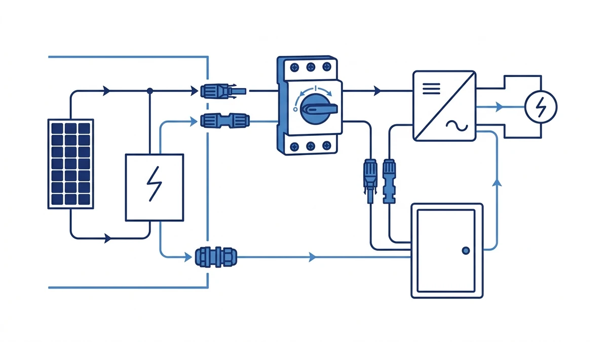
Figure 3. Application wiring context should be verified against the manufacturer contact chart before energizing.
Industry Standards and Compliance Requirements
Applicable Standards by Region and Entry Type
Three major regulatory frameworks address cable entry for PV DC isolators, and they each approach the topic from a different angle.
the current switch-disconnector standard edition applies to switches, disconnectors, switch-disconnectors, and fuse-combination units for distribution and motor circuits, with rated voltage up to 1000 V AC or 1500 V DC. It governs making and breaking capacity and rated insulation voltage but does not mandate a cable entry method. It does require that the completed assembly maintain its declared IP rating after installation. Buyers can access the current edition through the official IEC switch-disconnector publication.
IEC 60529 defines ingress protection classifications. An IP65-rated enclosure fitted with an M20 cable gland must maintain 65-class sealing when the gland is torqued to the gland manufacturer’s specified value. The declared IP rating of the enclosure body is not automatically transferred to the installed gland unless the gland is correctly selected, installed, and torqued.
IEC 62852 specifically governs MC4-type PV connector systems, setting requirements for current-carrying capacity, UV resistance after 1,000 hours of UV exposure per IEC 60068-2-5, and mating and unmating force limits. For a deeper explanation of what IP classifications mean in practice, the IP rating reference covers ingress protection classes and their practical implications for outdoor enclosures.
Regional Standards Summary
Standard
Jurisdiction
What It Governs
Relevance to Cable Entry
the current switch-disconnector standard edition
International
DC isolator switch ratings
Enclosure IP integrity post-installation
IEC 60529
International
IP ingress protection classes
Gland sealing compliance for M20 and M25
IEC 62852
International
PV connector systems
MC4 mating force, UV resistance, current rating
AS/NZS 5033
Australia and NZ
PV array wiring and safety
MC4 connector compatibility, cable type
NEC Article 690
USA
Solar PV systems
Wiring method, connector listing requirements
AS/NZS 5033 requires PV array cables to use connectors compliant with IEC 62852 or an equivalent listed standard, which in practice directs most Australian rooftop installations toward MC4 entries. NEC Article 690.33 requires PV source and output circuit connectors to be polarised, rated for the system DC voltage up to 1,500 V DC, and listed for use in PV systems. For installations referencing GF40 or GF51 series DC isolators, confirming the enclosure’s declared IP rating against the chosen entry method remains the installer’s responsibility under all three frameworks.
In coastal or industrial environments, specify brass or 316 stainless gland bodies rather than PA66 nylon. Nylon bodies can swell or crack under sustained UV and salt-spray cycling, gradually compromising the IP seal even when initially torqued correctly.
How Shieldhz Configures MC4 and M20 M25 Entry Options
Shieldhz is the export brand of Zhejiang Shihe Electric Co., Ltd., founded in 2014 and based in Yueqing, Zhejiang. The company operates a facility of over 5,000 m2 with 100+ employees and 40+ production machines, and holds ISO 9001, CE, RoHS, TUV, UL, UKCA, CCC, and CB certifications where applicable to the product family.
Entry Type Specification at Order Stage
When a buyer submits an inquiry for a GF40 or GF51 PV DC isolator, the Shieldhz technical team collects the following inputs before confirming a buildable configuration.
Cable type and cross-section. MC4 entry is confirmed for standard 4 mm2 or 6 mm2 PV single-core cable with factory-fitted connectors. M20 or M25 threaded entry is confirmed for multi-core cables, armoured cable, or conduit terminations where conductor cross-sections typically range across a wider spectrum. The exact conductor range that the selected model accepts is confirmed against the product datasheet, not assumed from the entry thread size alone.
Pole count and string count. The number of poles determines how many entry points are required, which directly affects whether the enclosure accommodates MC4 sockets at fixed spacing or M-threaded glands at configurable positions. This information is reflected in the enclosure drilling drawing supplied with the order.
IP rating requirement. Both entry types can be configured to maintain IP65 or IP67 per IEC 60529. MC4 entries use integrated sealing rings; M-threaded entries use IP-rated cable glands specified at the order stage. The IP rating of the assembled unit is confirmed in the supplied documentation, not inferred from the enclosure body rating alone.
Installation standard and market. Compliance documentation requirements vary by region. Shieldhz supplies CE declarations of conformity and, where required, the switch-disconnector standard test records relevant to the isolator’s rated voltage and interrupting category. Buyers requiring UL, TUV, or UKCA documentation should state this at inquiry stage so the appropriate certificate package is confirmed before order placement.
Documentation Package
For each confirmed configuration, Shieldhz provides a wiring diagram, enclosure dimensional outline, and drilling drawing specific to the selected entry type. For MC4-entry models, the drawing confirms socket centre positions and recommended mating connector torque range. For M20 or M25-entry models, the drawing specifies thread form, panel boss height, and gland selection guidance. The contact table and utilization category applicable to the rated current and voltage are included in the product datasheet.
Buyers who need to verify the isolator’s contact program, utilization category per the switch-disconnector standard, or IP rating against a project specification should request the full datasheet and dimensional drawing at inquiry stage. Model selection based on verbal descriptions alone, without reference to the datasheet and drawing, is the single most common source of post-delivery entry-type mismatches. The Shieldhz engineering team confirms the correct model route, entry configuration, and documentation package based on the buyer’s stated cable schedule, pole count, voltage, current, IP requirement, and certification needs.
Figure 4. A complete inquiry should include rating, contact sequence, mounting, enclosure, and document requirements.
8-Point Specification Checklist Before Raising a Purchase Order
String voltage and current rating — Confirm the isolator’s maximum DC voltage, typically 1000 V DC or 1500 V DC, and rated current against the string’s calculated open-circuit voltage and short-circuit current.
Cable entry type — Specify MC4 if direct panel-to-isolator connection eliminates intermediate terminations. Specify M20 or M25 metric thread if using conduit runs or non-MC4 cable ends.
Conductor cross-section compatibility — MC4 entries typically accept 4 mm2 or 6 mm2 PV wire. M20 glands accommodate approximately 6 mm to 12 mm OD cable. M25 glands suit approximately 9 mm to 17 mm OD cable. Verify exact limits against the datasheet.
Pole count — 2-pole for single-string ungrounded systems; 4-pole where both positive and negative conductors require simultaneous isolation per local installation codes.
Enclosure IP rating — Rooftop and outdoor ground-mount installations generally require IP65 minimum. Confirm IP66 or IP67 for high-wash or flood-risk environments per IEC 60529.
Utilization category — Confirm DC-21B or DC-22B per the switch-disconnector standard to ensure rated making and breaking capacity matches resistive and inductive PV load characteristics.
Mounting configuration — Surface-mount enclosures suit string combiner boxes; DIN-rail variants suit internal panel integration. Check knockout or pre-drilled entry positions against your gland layout.
Certification documentation — Request test reports, CE declaration of conformity, and the product datasheet confirming rated insulation voltage Ui and dielectric withstand values before placing the order.
For PV DC isolator models with configurable entry options, the GF41 solar DC switch and the GF40 and GF51 families cover a range of pole configurations and enclosure ratings suited to both MC4 and metric conduit entries. Submit your string voltage, current, cable OD, pole count, and required certifications to the Shieldhz technical team for model confirmation before procurement.
Frequently Asked Questions
Can I change a PV DC isolator from MC4 entry to M20 gland entry after it has been installed?
Entry type is determined by the housing cutout geometry machined during manufacture, so field conversion is generally not possible without replacing the enclosure body. Specify the correct entry format at the order stage. If a project’s cable schedule changes between design and installation, raise the change with the supplier before the manufacturing stage rather than attempting a site modification.
What happens to the IP rating if an MC4 connector is partially inserted?
A partially seated MC4 connector does not fully compress the O-ring against the mating socket face, leaving a gap that water and fine dust can penetrate. This effectively voids the enclosure’s IP65 or IP67 classification at that entry point. Always perform a pull-test after insertion to confirm full latch engagement. Do not rely on the audible click alone in cold-weather conditions when EPDM O-rings stiffen temporarily.
Is MC4 entry compliant with AS/NZS 5033 for Australian rooftop installations?
AS/NZS 5033 requires PV array connectors to meet IEC 62852 or an equivalent listed standard. MC4 connectors certified to IEC 62852 satisfy this requirement. Installers should confirm the specific product’s IEC 62852 certification before use on Australian rooftop systems, and should not assume certification based on the MC4 connector format alone.
Which entry type is better for a ground-mount system using armoured DC cable?
M25 cable glands are the appropriate choice for armoured cable runs on ground-mount arrays. They provide the mechanical clamping range and armour termination capability that MC4 connectors cannot accommodate. Confirm that the selected gland includes an armour clamp and that the clamp engages the armour layer before final torque is applied.
Do M20 and M25 glands require periodic re-torquing over the system service life?
Compression-nut glands can gradually loosen under sustained mechanical vibration or thermal cycling. Periodic inspection aligned with annual PV system maintenance is good practice. Applying a torque-indicator paint mark after initial installation makes any subsequent loosening immediately visible and reduces the risk of a sealing failure going undetected between scheduled inspections.
What is the difference between IP65 and IP67, and does it matter for cable entry selection?
IP65 certifies protection against low-pressure water jets from any direction. IP67 adds protection against temporary immersion to 1 m for 30 minutes. For most rooftop isolators, IP65 is sufficient. Ground-mount installations in flood-prone areas or wash-down environments should specify IP67 or higher, which typically requires correctly torqued M20 or M25 glands with an appropriately rated gland body rather than standard MC4 entries. The IP rating reference provides a detailed breakdown of each classification and the test conditions that define them.
Can MC4 and M20 M25 entries be used on the same isolator enclosure?
Some enclosure designs include both MC4 sockets and M-threaded knockouts on the same housing, allowing the installer to use whichever entry suits each cable run. Availability depends on the specific model configuration. Confirm the housing drawing with the manufacturer before assuming mixed-entry capability is available on the model you intend to order.
Shi, Muxi
Shi, Muxi writes Shieldhz technical articles for industrial control and electrical component buyers, covering rotary cam switches, isolator switches, PV DC disconnects, push buttons, indicator lights, waterproof enclosures, and terminal blocks. The articles are based on Zhejiang Shihe Electric Co., Ltd.'s manufacturing and export experience, with practical emphasis on model selection, datasheets, drawings, certifications, IP ratings, and inquiry details buyers should confirm before ordering.