DC Isolator Switch vs DC Circuit Breaker: Isolation and Protection Roles
DC isolator switch vs DC circuit breaker — understand isolation and protection roles, IEC standards, and how to select the right device. Get expert guidance from Shieldhz.
A DC isolator switch manually disconnects a circuit to create a safe, visible off-state for maintenance — it carries no automatic protective function. A DC circuit breaker automatically interrupts fault current, typically within milliseconds, to protect wiring and equipment. Neither device fully replaces the other; both roles are required in compliant DC installations.
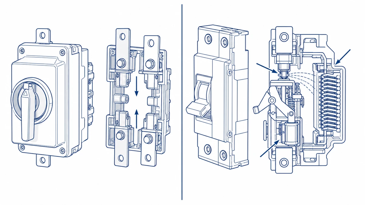
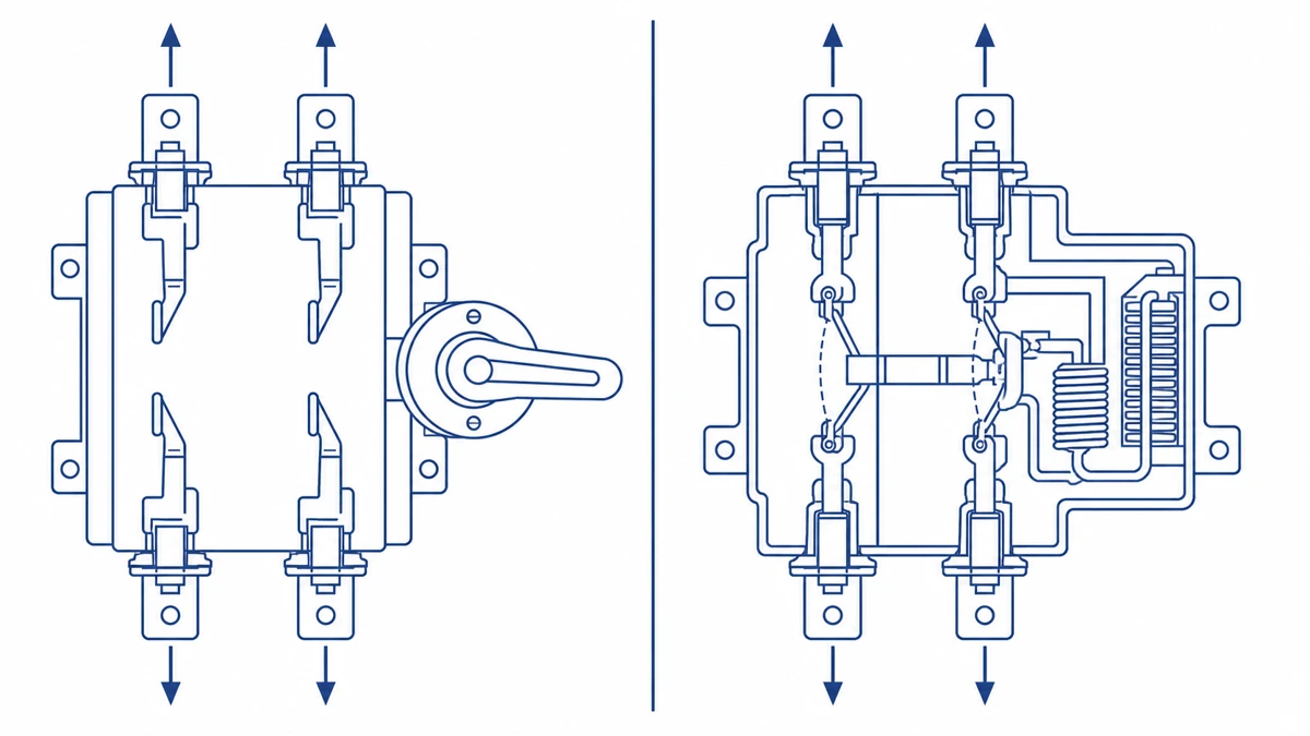
Figure 1. DC isolator switch (left) achieves isolation through mechanical contact separation and a visible air gap; DC circuit breaker (right) provides automatic fault interruption via a solenoid-actuated trip mechanism and arc chute — illustrating the non-overlapping functional boundaries defined under IEC 60947-3 and IEC 60947-2 respectively.
1. DC Isolator Switch vs DC Circuit Breaker: The One-Sentence Answer
Under IEC 60947-3, a disconnector (isolator) must achieve a minimum isolation distance sufficient to meet rated insulation voltage Ui — it is not required to make or break load current under fault conditions. A DC circuit breaker, governed by IEC 60947-2, must interrupt prospective short-circuit current, which in photovoltaic string applications commonly ranges from 1,000 V DC up to 1,500 V DC at fault currents several times the rated string current.
In a rooftop PV installation, a DC isolator switch rated for the array’s maximum open-circuit voltage is positioned at the inverter input so service personnel can de-energize the string before working on DC-side wiring. The circuit breaker handles overcurrent events the isolator is never designed to interrupt.
Selecting the wrong device for either role — using an isolator where automatic protection is required, or omitting an isolator where a visible break is mandated — creates both a code compliance gap and a safety hazard.
2. How Each Device Works: Operating Principles and Internal Mechanisms
DC Isolator Switch: Mechanical Contact Separation
A DC isolator switch operates by physically separating conductive contacts through a rotary or toggle actuator. In rotary designs, a cam-driven mechanism translates handle rotation into precise contact bridge separation. The resulting air gap must satisfy IEC 60947-3 requirements: a clearance distance typically no less than the minimum specified for the rated insulation voltage, ensuring the open-state withstands transient overvoltages without flashover.
DC circuits present a particular challenge during contact opening. Unlike AC current, which passes through zero 100–120 times per second, DC current maintains a continuous arc when contacts separate. To suppress this arc, quality DC isolator switches incorporate multi-pole series contact interruption — splitting the arc across two or more contact gaps — and may include magnetic arc-blowout geometry. In a typical 1,000 V DC PV installation, interrupting fault current without arc suppression hardware can sustain a destructive arc for several hundred milliseconds.
DC Circuit Breaker: Thermal-Magnetic Trip
A DC circuit breaker adds two automatic sensing elements to the switching mechanism. The thermal element — a bimetallic strip — deflects under sustained overload current, typically tripping within seconds to minutes depending on overcurrent magnitude. The magnetic element, a solenoid-actuated latch, responds to short-circuit currents within milliseconds, with interrupting ratings commonly specified at 6 kA–25 kA prospective fault current per IEC 60947-2.
When the trip mechanism releases, a stored-energy spring drives the contact carrier open rapidly. Arc runners and arc chutes — a stack of metal splitter plates — divide and cool the arc. In DC-rated breakers, the arc chute geometry is asymmetric to account for arc mobility under unidirectional current.
Key Mechanical Distinction
The isolator switch creates a visible, lockable isolation point under normal de-energized conditions. The circuit breaker operates continuously in-line and trips autonomously under fault. Neither device substitutes for the other’s function — a fact that governs how GF40 PV DC isolator switch selection criteria differ from breaker selection criteria in system design.
[Expert Insight] — DC Arc Suppression in the Field
– Magnetic arc-blowout effectiveness drops sharply when the contact gap geometry is not matched to the system voltage; always verify that the isolator’s rated DC voltage matches your worst-case Voc, not nominal string voltage.
– Multi-pole series interruption divides arc voltage across gaps — a 2-pole isolator effectively doubles the arc voltage the mechanism must sustain per gap, which is why single-pole AC-rated switches must never be substituted in DC string applications.
– Inspect arc chute chambers during scheduled maintenance; carbon deposits between deion plates reduce quenching efficiency and can cause re-strike under load switching.
– If arc-blowout magnets are present, verify polarity markings against current direction before installation — reversed polarity extends arc duration rather than reducing it.
3. DC Isolator Switch vs DC Circuit Breaker: Head-to-Head Comparison
Feature Comparison Table
Parameter
DC Isolator Switch
DC Circuit Breaker
Primary function
Manual isolation — creates a visible, lockable off-state
Automatic protection — interrupts overcurrent and short-circuit faults
Operation mode
Manual only
Automatic (trip) + manual reset/open
Interrupting rating
Rated for load-break at circuit operating current; not designed to clear short-circuit faults
Rated breaking capacity (Icu/Ics) typically 3 kA–50 kA at rated voltage
Governing standards
IEC 60947-3; IEC 60364 for PV DC isolators
IEC 60947-2; UL 489B for DC applications
Typical DC voltage range
Up to 1,500 V DC for PV-rated isolators
Commonly 250 V DC to 1,500 V DC depending on frame
String/array protection, battery system overcurrent, EV charging feeder
Arc quenching method
Contact gap geometry; magnetic blow-out in high-voltage designs
Arc chute chambers with deion plates
Installation context
Required by IEC 60364-7-712 at each PV inverter input
Placed upstream or within distribution boards
Why the Distinction Matters in Practice
In a rooftop PV installation, a DC isolator switch is placed between the string combiner and the inverter so maintenance personnel can create a confirmed de-energized state before working on wiring. A circuit breaker in the same system handles fault conditions that the isolator is not rated to interrupt — short-circuit currents that can reach several kiloamperes within microseconds.
The GF40 and GF51 PV DC isolator switches are rated for load-break isolation, not fault interruption. Selecting an isolator for a role requiring rated short-circuit breaking capacity is a code violation under IEC 60947-3, which explicitly prohibits using a disconnector as a substitute for a protective device.
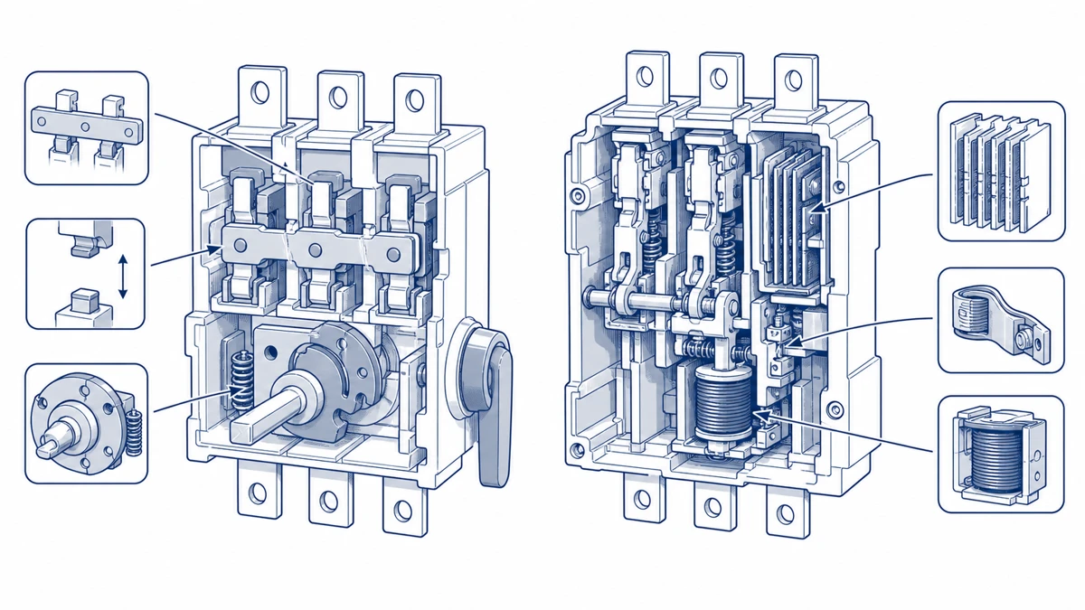
Figure 2. Internal component comparison: DC isolator switch (left) showing contact bridge, cam actuator, and rated air gap; DC circuit breaker (right) showing bimetallic overload element, overcurrent solenoid, and arc chute deion plates — the arc chute asymmetry accounts for unidirectional DC arc mobility under IEC 60947-2.
4. Application Scenarios: Which Device Belongs Where in a DC System?
Application Scenario Matrix
System
Isolator Switch Role
Circuit Breaker Role
Solar PV (rooftop/ground-mount)
String-level and array-level disconnect for maintenance and firefighter access
Array combiner or inverter input overcurrent protection
Battery storage (BESS)
Manual isolation of battery bank before servicing or cell replacement
Short-circuit and overcurrent protection at the DC bus
EV charging infrastructure
Service isolation of charging module, typically rated up to 1,000 V DC
Feeder protection at the AC/DC conversion stage
Industrial DC bus (24–750 V DC)
Segment isolation during planned shutdowns or panel access
Load branch protection for motors and actuators
Solar PV: Where Isolators Are Mandated
In rooftop PV installations, a DC isolator is typically required within 600 mm of the inverter by most national installation standards (verify against the applicable regional code, such as AS/NZS 5033 or equivalent). Rated working voltages for residential systems commonly reach up to 1,000 V DC, while utility-scale arrays may reach 1,500 V DC. The isolator creates a defined off-state for firefighter or service access — it does not need to clear fault current. For this application, IP65-rated enclosures are generally required for outdoor string combiners. The Shieldhz GF40 and GF51 series DC isolator switches address this segment with PV-rated contact construction and weatherproof housings.
Battery Storage and Industrial DC Bus
At the battery bank terminals, the isolator provides maintenance isolation; the circuit breaker upstream handles fault clearing. On an industrial DC bus operating at 48 V to 750 V DC, isolators placed at each panel section allow technicians to de-energize specific zones without disconnecting the entire system. For installations requiring outdoor or conduit-entry mounting, the UKP waterproof isolator switch provides an IP65-rated enclosure option suited to wet or dusty environments.
EV Charging Infrastructure
DC fast chargers typically route service isolation at the charging module level. The isolator disconnects the DC output for module swaps or inspection, while circuit breakers protect the AC supply feeder. This separation of roles — isolation versus protection — is the central specification decision for both device types in EV charging design.
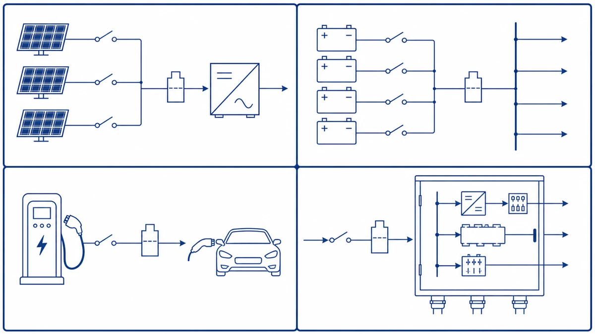
Figure 3. Application matrix illustrating correct device placement across four DC system types: rooftop PV string isolation (top-left), battery bank maintenance disconnect (top-right), EV charging module isolation (bottom-left), and industrial DC bus segmentation (bottom-right) — isolator switch and circuit breaker positions are non-interchangeable in each topology.
[Expert Insight] — Field Placement and Commissioning
– Confirm that the isolator is accessible without exposing the technician to live conductors from adjacent strings — physical separation or shrouding of adjacent combiner outputs is often required before the isolator handle is reachable.
– For battery BESS applications, always verify that the isolator’s rated operational current covers the battery’s maximum continuous discharge current, not only charge current — discharge peaks are typically higher and affect contact wear.
– At the EV charging module level, document the isolator position in the as-built single-line diagram; regulators increasingly require a marked isolation point per charging bay for emergency responder access.
5. Can a DC Isolator Replace a DC Circuit Breaker — or Vice Versa?
When an Isolator Cannot Replace a Circuit Breaker
A DC isolator is designed to disconnect a de-energized or low-current circuit under controlled conditions. It does not carry a defined interrupting rating for fault current. Under IEC 60947-3, a disconnector is explicitly not required to make or break short-circuit current — that responsibility belongs to a protective device. In a PV string operating at 1,000 V DC with prospective fault currents exceeding 10 kA, placing only an isolator in the overcurrent protection role would leave conductors, inverters, and modules exposed to sustained arc energy.
When a Circuit Breaker Cannot Replace an Isolator
A circuit breaker provides overcurrent and short-circuit protection but is generally not rated as a means of isolation under IEC 60947-2, unless it also carries a disconnector designation confirmed on its nameplate. Maintenance safety procedures — such as lockout/tagout — require a device that provides a visible or verifiable open-contact gap. In solar installations, regulations in many jurisdictions require a dedicated DC isolator switch within 600 mm of the inverter as the primary service isolation point, independent of any upstream breaker.
Decision Logic: Which Device Goes Where
Fault protection role → DC circuit breaker (overcurrent, short-circuit interrupting capacity rated in kA)
Maintenance isolation role → DC isolator switch (visible-break, lockable, rated for the string voltage and current)
Both roles required → Install both in series; some markets accept a switch-disconnector with both ratings confirmed on the same nameplate
For rooftop PV and off-grid battery systems, the GF40 PV DC isolator fulfills the isolation requirement at rated DC voltage and string current — but it must be paired with a correctly sized circuit breaker upstream or downstream to cover the protection function.
6. How Shieldhz Configures and Verifies DC Isolator Switches for Buyer Projects
Step 1: Voltage Rating and Utilization Category Confirmation
The first input Shieldhz requests is the system’s maximum open-circuit voltage (Voc) at worst-case conditions, not nominal string voltage. For PV applications, this figure determines which product series applies — the GF40 and GF51 PV DC isolator switches cover voltage ranges that buyers should confirm against their string calculations and the applicable installation standard. Rated insulation voltage (Ui) and rated operational voltage (Ue) are reviewed separately, as DC arc quenching imposes stricter derating than equivalent AC ratings under IEC 60947-3.
Step 2: Pole Configuration and Current Path Mapping
Buyers provide a circuit diagram or string layout showing how many poles are required and whether a linked neutral or floating-reference arrangement is used. For isolated DC systems, a 2-pole configuration isolates both positive and negative conductors simultaneously — the arrangement most commonly required under residential PV installation standards. Current rating is cross-checked against the string’s maximum short-circuit current (Isc) multiplied by the number of parallel strings.
Step 3: Enclosure Class and Mounting Environment
For rooftop or outdoor combiner-box installations, buyers specify the required IP rating. IP65 provides dust-tight and low-pressure water-jet protection; IP66 provides protection against powerful water jets. The UKP waterproof isolator box product line is reviewed when the buyer needs an integrated enclosure rather than a panel-mount switch body. Ingress protection is verified against IEC 60529 designations.
Step 4: Documentation Package
Before shipment, Shieldhz confirms which certificates and documents the buyer’s market requires — typically including dimensional drawings, wiring diagrams, test reports, and CE declarations. Buyers requiring third-party certification should specify this at the inquiry stage, as documentation scope affects production lead time.
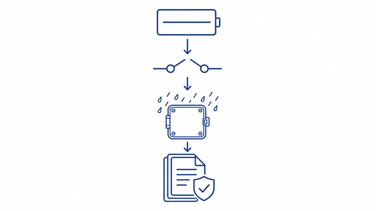
Figure 4. Shieldhz four-step DC isolator switch order verification flow: (1) maximum open-circuit voltage confirmation, (2) pole configuration and current path mapping, (3) enclosure IP class selection per IEC 60529, and (4) documentation package scope — each step determines product eligibility and production lead time.
7. Selecting the Right Device: A Practical Checklist for Buyers and Designers
Step 1 — Define the Primary Function
Ask: does this circuit position need safe isolation for maintenance, automatic overcurrent protection during operation, or both? Isolation and protection are distinct IEC 60947-3 and IEC 60947-2 functions — specifying one device for both roles without verifying its combined rating on the nameplate is a common design error.
Step 2 — Confirm Voltage and Current Ratings
Identify the maximum DC operating voltage (for example, 1,000 V DC for most residential PV strings, up to 1,500 V DC for utility-scale arrays) and the maximum continuous current. Check that the selected device carries a DC-specific rated insulation voltage (Ui) and making/breaking capacity at that voltage — AC ratings do not transfer directly to DC circuits due to the absence of a natural current zero-crossing.
Step 3 — Count Poles and Verify Arc Interruption
DC arcs do not self-extinguish at zero crossing. Confirm pole count and contact separation distance are sized for the actual DC voltage. For PV applications, confirm the inverter-side DC disconnect requirements against the applicable installation standard for your jurisdiction (such as IEC 62109-1 or a regional equivalent).
Step 4 — Check Environmental Rating
Outdoor or rooftop installations may require an IP-rated enclosure. Confirm the selected enclosure’s datasheet IP rating against the actual site classification before ordering.
Step 5 — Submit Specifications for Confirmation
When contacting Shieldhz, provide: DC voltage, string current, pole count, enclosure IP requirement, applicable installation standard, and any certification documentation needed. For standards context, see the IEC 60947-3 disconnector selection guidance from IEC, and browse the full DC isolator switch range to identify candidate models before enquiry.
Frequently Asked Questions
What is the main difference between a DC isolator switch and a DC circuit breaker?
A DC isolator switch provides a manually operated, visible disconnection point for safe maintenance access, while a DC circuit breaker automatically interrupts the circuit when it detects overcurrent or short-circuit conditions. The two perform non-overlapping functions and are typically required together in compliant DC installations.
Can I use a DC circuit breaker as an isolator switch in a solar PV system?
A standard DC circuit breaker does not qualify as an isolating device under IEC 60947-2 unless it explicitly carries a disconnector designation confirmed on the nameplate. Most PV installation codes mandate a dedicated DC isolator within a specified distance of the inverter as the primary maintenance disconnect, regardless of upstream breakers.
Why do DC isolator switches have special arc suppression requirements compared to AC devices?
AC current passes through zero 100–120 times per second, which naturally extinguishes an arc at each crossing. DC current has no zero crossing, so an arc formed when contacts open must be actively quenched through contact gap geometry, magnetic arc-blowout, or multi-pole series interruption — all of which are absent in standard AC-rated switches.
What voltage ratings should I look for in a DC isolator switch for a rooftop solar system?
For residential rooftop PV, the isolator must be rated for the array’s maximum open-circuit voltage (Voc) under worst-case temperature conditions, which commonly reaches 1,000 V DC. Utility-scale systems may require 1,500 V DC rated devices. Always match the isolator’s rated insulation voltage (Ui) to the calculated Voc, not the nominal string voltage.
Is an IP65 enclosure sufficient for an outdoor DC isolator switch installation?
IP65 provides dust-tight protection and resistance to low-pressure water jets, which is adequate for most rooftop and ground-mount PV installations. Sites exposed to high-pressure washdown, driving rain at angles, or submersion risk should consider IP66 or higher — verify the enclosure rating against the IEC 60529 classification for your specific site conditions.
Do I need both a DC isolator switch and a DC circuit breaker in a battery storage system?
Yes. The isolator provides a safe maintenance disconnect at the battery bank terminals, while the circuit breaker upstream protects the DC bus from short-circuit and overcurrent faults that the isolator is not rated to interrupt. Omitting either device leaves a gap in either personnel safety or fault protection.
How do I confirm the correct pole count for a DC isolator switch?
The pole count depends on whether the DC system uses a grounded or floating reference. Isolated (floating) DC systems — common in PV strings — typically require a 2-pole configuration to simultaneously break both the positive and negative conductors. Confirm the system reference arrangement in the circuit diagram before specifying single-pole or multi-pole units.
Shi, Muxi
Shi, Muxi writes Shieldhz technical articles for industrial control and electrical component buyers, covering rotary cam switches, isolator switches, PV DC disconnects, push buttons, indicator lights, waterproof enclosures, and terminal blocks. The articles are based on Zhejiang Shihe Electric Co., Ltd.'s manufacturing and export experience, with practical emphasis on model selection, datasheets, drawings, certifications, IP ratings, and inquiry details buyers should confirm before ordering.