Choosing between the GF40, GF51, and GF41 DC isolator switches comes down to three engineering variables: maximum string voltage, rated continuous current, and whether the installation site demands a self-contained weatherproof enclosure. The GF40 suits residential PV panel-mount applications rated up to 1000 V DC. The GF51 extends to 1500 V DC for commercial or utility-scale strings. The GF41 integrates an IP-rated enclosure for exposed outdoor positions. All three series are designed to the switch-disconnector certificate scope and carry the DC-PV2 utilization category for photovoltaic duty. Confirm the exact rated values against the relevant datasheet before specifying any model.
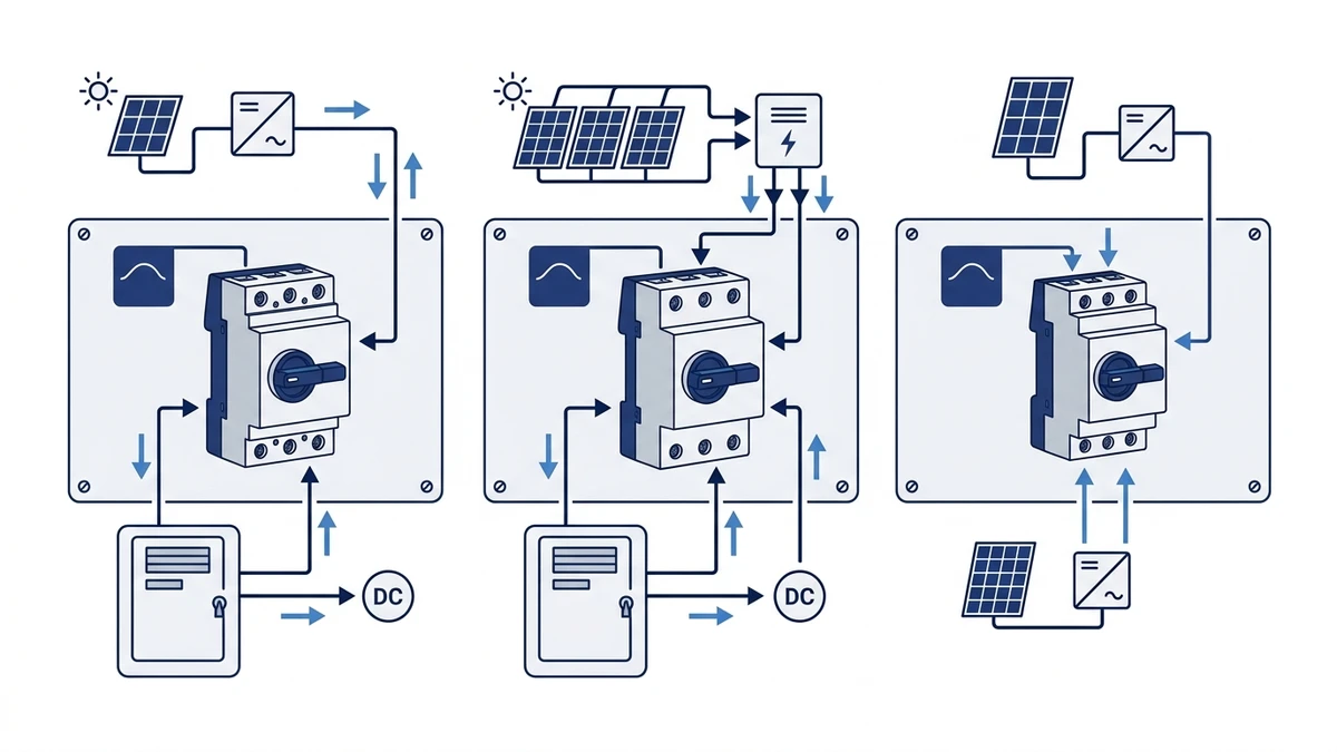
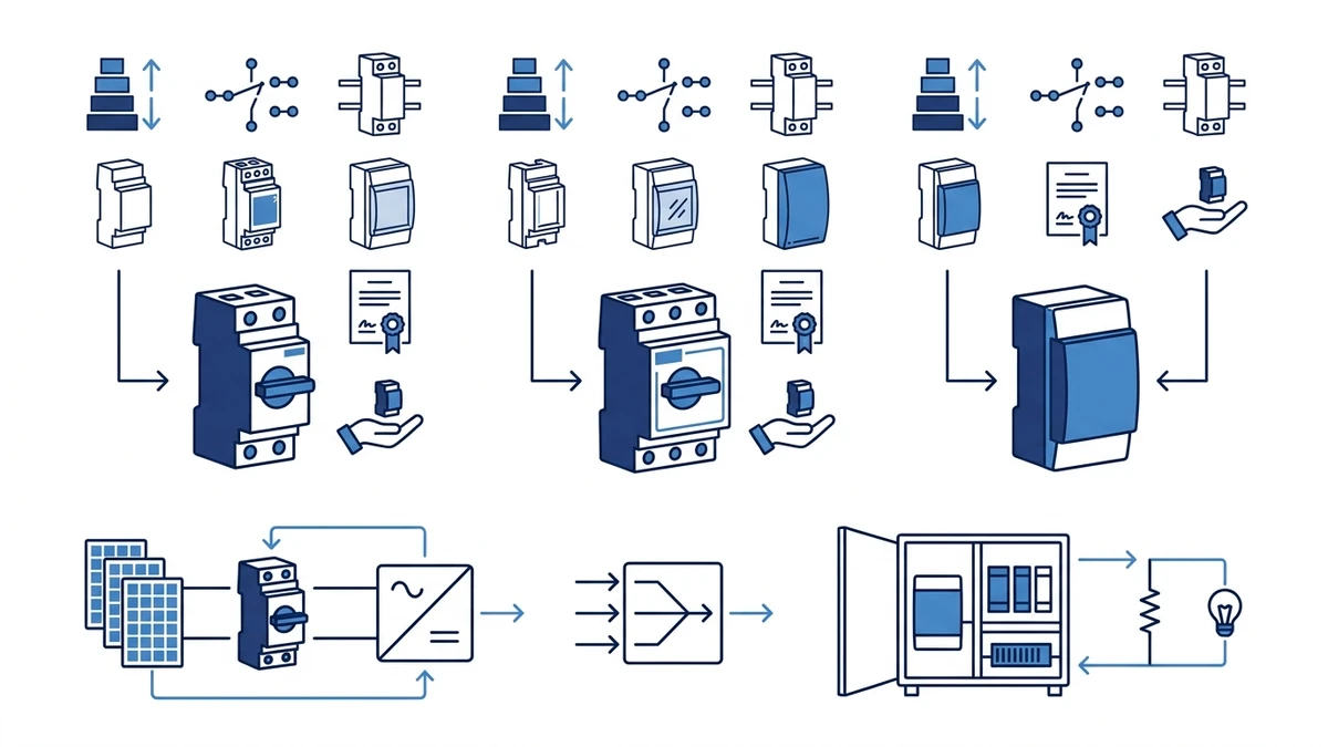
Figure 1. Core concept behind GF40 vs GF51 vs GF41 DC isolator selection.
Why These Three Models Cover Different Tiers of PV DC Isolation
The GF40, GF51, and GF41 are not interchangeable variants of the same product. Each occupies a distinct position in the DC isolator switch product range defined by electrical rating, mechanical architecture, and enclosure format. Understanding where those tiers begin and end prevents under-specification at the voltage boundary and avoids paying for enclosure integration that a panel-mounted build does not require.
Voltage, Current, and Enclosure at a Glance
Do not treat this comparison as a universal specification sheet. GF40, GF51, and GF41 ratings, enclosure routes, certificate coverage, and accessories must be confirmed against the current Shieldhz datasheet, drawing, and documentation package for the exact model ordered.
Parameter
GF40
GF51
GF41
Rated DC Voltage
Up to 1000 V DC
Up to 1500 V DC
Up to 1000 V DC
Rated Current
Confirm per datasheet
Confirm per datasheet
Confirm per datasheet
Pole Options
2P / 4P
2P / 4P
2P / 4P
Utilization Category
DC-PV2
DC-PV2
DC-PV2
Enclosure Format
External enclosure required
External enclosure required
Integrated IP enclosure
Primary Differentiator
Compact panel-mount footprint
1500 V DC ceiling
Self-contained weatherproofing
Applicable Standard
the switch-disconnector standard
the switch-disconnector standard
the switch-disconnector standard
All values above are reference tiers. Confirm exact rated current, rated insulation voltage Ui, IP class, and contact program against the selected model datasheet and certification documentation before finalising specification.
The 1000 V DC vs 1500 V DC Boundary
The most consequential electrical distinction in this comparison is the GF51’s 1500 V DC ceiling. Modern utility and large commercial PV string architectures regularly approach or exceed 1400 V DC open-circuit voltage under cold-morning conditions when the temperature correction factor from IEC 60364-7-712 is applied. The GF40 and GF41, both rated to 1000 V DC, are not appropriate in those configurations regardless of current rating. Engineers should calculate the temperature-corrected Voc for the specific module and site latitude before selecting a voltage tier. Cold-weather peak Voc can exceed the nameplate module voltage by a meaningful margin depending on the temperature coefficient and minimum site temperature.
The GF40 and GF41 share a voltage tier but serve different enclosure requirements. Where a control panel or inverter cabinet already provides the weatherproof housing, the GF40 is the more compact and cost-appropriate choice. Where the isolator must mount directly at a rooftop combiner point or string junction box without an external enclosure, the GF41 removes that dependency.
For a broader explanation of what these products do at the circuit level, the PV DC isolator switch guide covers the functional and regulatory basis for isolation requirements in solar installations.
Structural Differences: Contact Design, Housing, and Pole Layout
Headline voltage and current figures do not fully describe how an isolator performs under DC fault conditions. Contact bridge geometry, arc suppression architecture, and housing footprint each influence performance and physical fit in ways that are not visible in a summary specification table.
Contact Bridge Architecture
All three series use silver-based contact alloys rated for DC breaking duty. The GF40 and GF51 employ a double-break contact bridge per pole, meaning each switching event interrupts the circuit at two points in series within the same pole chamber. This configuration reduces the arc energy that must be extinguished at each individual contact gap, which is particularly relevant when isolating unloaded PV strings where voltage reaches the open-circuit level with no current-limiting load in the circuit.
The GF41’s contact program may differ by frame and pole configuration. Confirm the contact bridge type against the specific datasheet for the configured model, as single-break and double-break options can both be available within a product family depending on the current rating and utilization category variant ordered.
Creepage, Clearance, and Housing Dimensions
The GF51’s housing is physically larger than the GF40 to maintain the creepage and clearance distances required at 1500 V DC. the current switch-disconnector standard edition, which applies to switches, disconnectors, switch-disconnectors, and fuse-combination units for distribution and motor circuits with rated voltage up to 1000 V AC or 1500 V DC, specifies the insulation coordination requirements that drive these dimensional constraints. Where the GF40 and GF41 share a narrower housing envelope suited to compact control panels, the GF51 requires more physical space per pole to meet the elevated voltage insulation requirements.
Panel builders should obtain the dimensional drawing for each model and verify the exact panel cutout size and busbar pitch before committing to enclosure fabrication. Housing dimensions are model- and frame-specific and must be confirmed from the drawing, not estimated from a comparison table.
Pole Layout and Multi-String Applications
The 2-pole configuration isolates a single PV string by breaking both the positive and negative conductors. The 4-pole configuration is required for bipolar arrays, floating-earth installations, or cases where two strings must be simultaneously isolated from a single actuator. The GF51’s pole architecture also supports multi-string combiner applications where simultaneous disconnection of several string pairs from one rotary handle is operationally important. Confirm the specific pole layout and actuator coupling with Shieldhz before specifying for multi-string configurations.
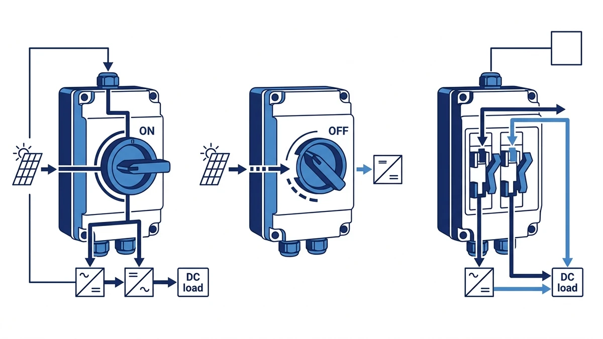
Figure 2. Selection checks should connect DC voltage, string current, pole count, enclosure, cable entry, and documentation.
Application Mapping: Solar PV, Energy Storage, and Industrial DC
Structural and electrical differences translate directly into distinct application niches. The matrix below maps each model to its primary use case and states the engineering justification. Entries marked as “Confirm” require datasheet verification before the application can be finalised.
Application Scenario
Recommended Model
Engineering Justification
Residential rooftop PV, single string, up to 1000 V DC
GF40
Compact panel-mount footprint, DC-PV2 duty, 1000 V DC ceiling
Commercial rooftop PV, long strings approaching 1400-1500 V DC Voc
GF51
1500 V DC rated insulation voltage, DC-PV2 utilization category
Outdoor string combiner, exposed rooftop or ground-mount junction
GF41
Integrated IP enclosure eliminates separate weatherproof box
Battery energy storage system DC bus isolation
GF51
Wider voltage range; confirm rated current against pack discharge current
Industrial DC control panel input, motor drive feed
GF40 / GF41
Confirm utilization category against load type; DC-PV2 differs from DC-21A
EV charging station DC side isolation
GF51
Voltage ceiling and pole flexibility; confirm rated making/breaking capacity
Selecting for PV String Circuits
For PV string isolation, the minimum requirement is that the isolator’s rated DC working voltage meets or exceeds the temperature-corrected open-circuit voltage of the string at the lowest expected site temperature. Engineers should apply the module’s voltage-temperature coefficient and the minimum design ambient temperature before selecting a voltage tier. The GF40 PV DC isolator covers standard residential strings within the 1000 V DC limit. The GF51 PV DC isolator covers commercial and utility configurations where the temperature-corrected Voc exceeds the GF40’s rating. The GF41 solar DC switch covers the same voltage tier as the GF40 but in an integrated housing for exposed field positions.
Selecting for Battery Storage and Industrial DC
For BESS applications, the critical sizing parameter is the fully charged pack voltage rather than the nominal bus voltage. A battery bank with a 48 V nominal voltage can reach significantly higher voltage at full state of charge under float conditions. Size the isolator’s rated insulation voltage Ui to the maximum expected voltage at full charge, not the nameplate figure. For industrial motor drive inputs, verify that the required utilization category is compatible with the isolator’s rated breaking capacity; PV-duty DC-PV2 ratings address resistive-capacitive PV source behaviour and may differ from the inrush characteristics of a large drive input capacitor bank.
Documentation and Certificate Scope Checks
Standard Scope Without Making the Article a Standard Page
All three models are designed in reference to the switch-disconnector standard. The current edition, official IEC switch-disconnector publication, applies to switches, disconnectors, switch-disconnectors, and fuse-combination units for distribution and motor circuits with rated voltage up to 1000 V AC or 1500 V DC. This standard sets the requirements for rated making and breaking capacity, mechanical and electrical endurance, dielectric withstand, and temperature rise that each model must satisfy for its assigned utilization category and rated voltage. For a plain-language explanation of what the switch-disconnector standard requires in practice, the switch-disconnector standard guide summarises the key clauses relevant to DC isolator selection.
IEC 60947-1 establishes the general rules for low-voltage switchgear that underpin the switch-disconnector standard, covering dielectric withstand, temperature rise limits, and short-circuit ratings. IEC 60529 defines the ingress protection classification relevant to enclosure ratings. For IP rating definitions applicable to GF41 and outdoor installation decisions, the IP rating guide explains what each protection class requires in practice.
Certification Scope by Model
The following is a reference summary. Buyers must request current certificates directly from Shieldhz, as documentation packages and available marks vary by export market and model variant.
Model
Reference Standard
CE
IP Class
DC Voltage Scope
GF40
the switch-disconnector standard
Available
Confirm per datasheet
Up to 1000 V DC
GF51
the switch-disconnector standard
Available
Confirm per datasheet
Up to 1500 V DC
GF41
the switch-disconnector standard
Available
Confirm per datasheet
Up to 1000 V DC
For projects requiring documentation for utility interconnection review or third-party commissioning audits, the standard package requested from Shieldhz includes the CE declaration of conformity, the switch-disconnector standard test report, IP rating certificate per IEC 60529, dimensional drawing, and wiring diagram for the intended pole configuration. Confirm which certificates are required for the target market before placing an order.
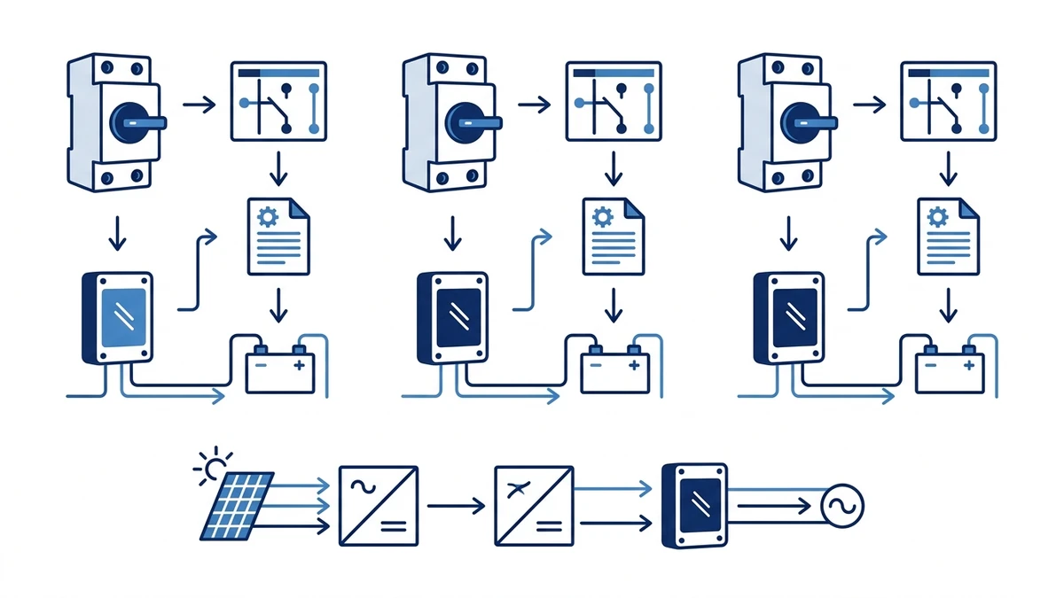
Figure 3. Application wiring context should be verified against the manufacturer contact chart before energizing.
How Shieldhz Confirms the Model Route for GF40, GF51, and GF41 Orders
Shieldhz is the export brand of Zhejiang Shihe Electric Co., Ltd., founded in 2014 and based in Yueqing, Wenzhou, Zhejiang Province. The company operates from a factory exceeding 5000 square metres with more than 100 employees and over 40 production and test machines. Quality certifications include ISO 9001, and relevant product certifications include CE, RoHS, TUV, UL, UKCA, CCC, and CB depending on model and target market.
Buyer Inputs Required Before Model Confirmation
For any GF40, GF51, or GF41 inquiry, Shieldhz requests the following parameters before confirming a buildable configuration:
Maximum DC operating voltage and temperature-corrected open-circuit voltage for the intended circuit
Rated continuous DC current and prospective short-circuit current at the point of installation
Required pole count and actuator type
Enclosure IP class required by the installation environment and local regulation
Applicable installation standard or market certification documentation required at commissioning
Panel cutout constraints or enclosure drawing if the isolator must fit within a defined footprint
Verification Before Supply
Once these parameters are received, Shieldhz cross-checks the contact program, rated making and breaking capacity at the operating voltage and utilization category, wiring diagram, and dimensional drawing against the buyer’s enclosure or panel design. This review step identifies mismatches between the specified configuration and the physical installation before production rather than after delivery.
Datasheets, test certificates, and dimensional drawings are provided at quotation stage. This allows engineering reviewers to compare the GF40, GF51, and GF41 side by side against their full specification requirements before committing to a configuration or releasing a purchase order. Specification errors caught at quotation review eliminate field rework and commissioning delays.
Installation, Wiring, and Safety Considerations
Correct model selection becomes effective only when the installation matches the datasheet conditions. DC circuit isolation presents arc hazards that differ fundamentally from AC switching, and installation errors that are benign in AC applications can cause sustained arcing and contact welding in DC circuits.
Pre-Installation Verification Checklist
Before mounting any DC isolator from the GF series, confirm each of the following against the selected model datasheet:
System temperature-corrected Voc does not exceed the isolator’s rated DC working voltage
Continuous DC current at maximum generation does not exceed the rated current at the installation ambient temperature
Conductor cross-section and terminal torque match the values specified on the datasheet; under-torqued terminals increase contact resistance and create localised heating at DC current levels
Pole count matches the circuit polarity arrangement: 2-pole for single-string unipolar, 4-pole for bipolar or floating-earth configurations
Enclosure IP class meets or exceeds the requirement for the installation environment
Cable gland sizing preserves the enclosure IP rating after cable entry
Wiring Sequence
Step 1: Shade or cover PV modules to reduce string current to the lowest practicable level before connecting conductors.
Step 2: Route DC positive and negative conductors through separate conduit entries to prevent polarity reversal during installation.
Step 3: Torque terminal screws to the value specified on the datasheet. The datasheet torque figure is specific to the terminal block design and conductor cross-section range.
Step 4: Mount the isolator at the position required by the applicable installation standard. Many jurisdictions specify accessible disconnection within a defined distance of the inverter DC input terminals.
Step 5: Apply polarity markers and warning labels rated for UV exposure at outdoor positions before energising the circuit.
DC Arc Hazard Warnings
Never break a live DC circuit using an isolator that does not carry a DC utilization category appropriate to the load type. An isolator rated only for AC duty or for a lighter DC utilization category than the circuit requires risks a sustained arc that does not self-extinguish. Confirm the utilization category on the product label and datasheet matches the circuit duty before operating under load.
Do not exceed the isolator’s rated making and breaking capacity. Inverter input capacitors and battery management systems can present transient current conditions that differ from steady-state PV string behaviour. Confirm the rated short-circuit making capacity for the GF51 before connecting to high-capacitance DC bus inputs.
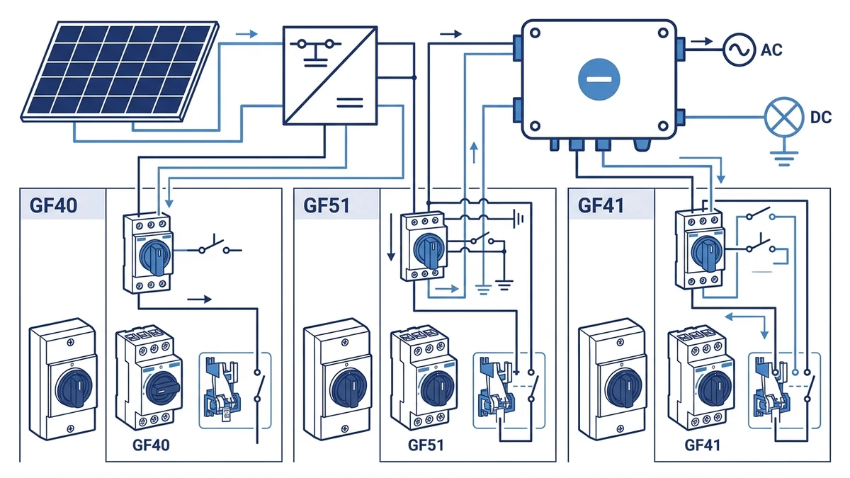
Figure 4. A complete inquiry should include rating, contact sequence, mounting, enclosure, and document requirements.
Frequently Asked Questions
What is the main electrical difference between the GF40 and GF51 DC isolator switches?
The primary difference is rated DC voltage. The GF51 is rated up to 1500 V DC, which accommodates commercial and utility-scale PV string configurations where the temperature-corrected open-circuit voltage approaches or exceeds the 1000 V DC ceiling of the GF40. Both models carry the DC-PV2 utilization category and are available in 2-pole and 4-pole configurations. For installations where the string voltage does not exceed 1000 V DC, the GF40 is the more compact and typically more cost-appropriate choice.
Can the GF41 replace a separate DC isolator and weatherproof enclosure in one unit?
The GF41 integrates the switching mechanism with an IP-rated enclosure, which removes the need to specify and install a separate weatherproof box at exposed outdoor positions such as rooftop combiner points or ground-mount string junction locations. Confirm the exact IP class against the GF41 datasheet for the specific variant ordered, and verify that the cable gland sizing after installation maintains that rating.
Which model is appropriate for a battery energy storage system DC bus?
The GF51 is generally the more appropriate starting point for BESS applications because its 1500 V DC rating provides headroom above the fully charged pack voltage for most commercially available battery chemistries. Engineers should size to the fully charged pack voltage rather than the nominal bus voltage. Confirm the rated continuous current and utilization category against the expected discharge current and load type, as BESS loads may present different breaking characteristics than PV source circuits.
Do all three models use the same certificate scope?
All three series are designed to the switch-disconnector standard, the standard governing disconnectors, switch-disconnectors, and related devices for circuits with rated voltage up to 1000 V AC or 1500 V DC. CE marking is available for all three models. Buyers should request the current declaration of conformity and the switch-disconnector standard test report from Shieldhz before finalising specification, as documentation packages may vary by export market and model variant.
How do I choose between a 2-pole and 4-pole configuration?
A 2-pole isolator simultaneously breaks both the positive and negative conductors of a single unipolar PV string, which is appropriate for standard string inverter installations with a defined earthed negative or positive rail. A 4-pole configuration is required where both conductors of two strings must be simultaneously isolated, or in bipolar and floating-earth systems where neither conductor is earthed and full circuit isolation requires breaking all active conductors in a single operation. Confirm the earthing arrangement and pole count requirement with the installation designer before ordering.
Is temperature derating required at high ambient temperatures?
Yes. Rated continuous DC current values apply at the reference ambient temperature stated on the datasheet, typically 40 degrees C. Installations in enclosed combiner boxes, unventilated outdoor enclosures, or hot climates where ambient temperatures regularly exceed that reference value should apply the derating factor from the datasheet to determine the permissible operating current. Operating above the rated thermal limit accelerates contact wear and can reduce isolation integrity over the product’s service life.
What documentation should I request before specifying any of these three models?
The standard documentation package for a verified GF-series order includes the CE declaration of conformity, the switch-disconnector standard test report, IP rating certificate per IEC 60529, dimensional drawing with panel cutout dimensions and busbar pitch, and the wiring diagram for the intended pole configuration and contact program. Shieldhz provides these at quotation stage to allow engineering review before production is confirmed. For projects subject to utility interconnection requirements or third-party commissioning audits, confirm the required certification scope with the authority having jurisdiction before requesting quotation.
Shi, Muxi
Shi, Muxi writes Shieldhz technical articles for industrial control and electrical component buyers, covering rotary cam switches, isolator switches, PV DC disconnects, push buttons, indicator lights, waterproof enclosures, and terminal blocks. The articles are based on Zhejiang Shihe Electric Co., Ltd.'s manufacturing and export experience, with practical emphasis on model selection, datasheets, drawings, certifications, IP ratings, and inquiry details buyers should confirm before ordering.