Address
304 North Cardinal St.
Dorchester Center, MA 02124
Work Hours
Monday to Friday: 7AM - 7PM
Weekend: 10AM - 5PM
Address
304 North Cardinal St.
Dorchester Center, MA 02124
Work Hours
Monday to Friday: 7AM - 7PM
Weekend: 10AM - 5PM
Get premium rotary switches, isolators, and panel components directly from the manufacturer.
Fill out the form below for pricing, catalogs, and technical support.
Learn LW28 rotary cam switch basics, selection checks, wiring context, IEC 60947-3 notes, and Shieldhz buyer guidance.
The LW28 rotary cam switch is a multi-position selector switch that uses precision-machined cam discs to open and close discrete contact circuits as the actuator shaft rotates through defined angular steps. Shieldhz positions LW28 as a 10A to 315A IEC 60947-3 rotary cam switch family; the usable operational current and voltage depend on the selected frame, contact program, and utilization category. It is a core component in industrial control panels, motor starter circuits, and changeover applications. If you are specifying a switch for a 2-source changeover circuit, a forward/reverse motor drive, or a star-delta starter, the LW28 delivers mechanically encoded, multi-pole contact sequencing in a panel-mount format selected from the specific LW28 frame drawing. This article covers contact sequence charts, pole and position selection, wiring procedures, installation tolerances, and fault diagnosis — everything a panel builder or control engineer needs to work with the LW28 confidently.
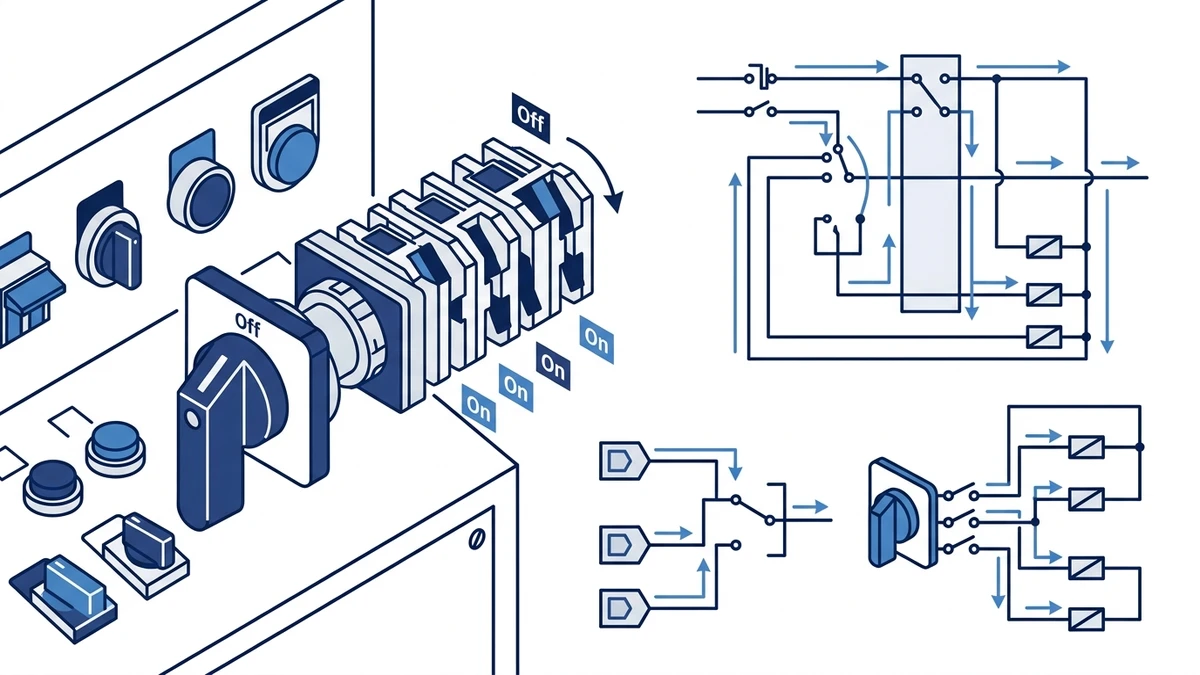
Inside the LW28, a stack of cam discs mounts directly on a central actuator shaft. Each disc carries a unique lobe profile that engages or releases a spring-loaded contact bridge as the shaft rotates — typically in 30, 45, or 90 degree increments depending on the pole configuration. This mechanical encoding means each switch position produces a repeatable, pre-defined contact state across multiple poles simultaneously, without relying on electronic logic or auxiliary relays.
Contact bridges in the LW28 series use silver-alloy construction. The cam profile tolerances are held tight enough to ensure consistent contact wiping action across the rated mechanical endurance of the switch. For the governing standard, see IEC 60947-3:2020+AMD1:2025, which applies to switches, disconnectors, switch-disconnectors, and fuse-combination units for distribution and motor circuits, with rated voltage up to 1000V AC or 1500V DC.
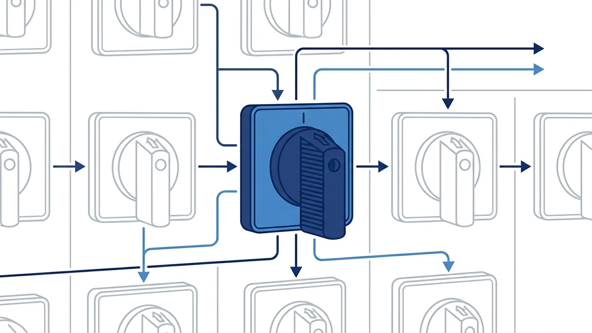
In a typical motor control panel, the LW28 serves as the primary mode selector — switching between off, manual, and automatic operating states, or routing power between two supply sources in a changeover circuit. Its multi-pole architecture allows a single operator action to simultaneously reconfigure several independent circuit paths, reducing wiring complexity and the risk of operator error.
For engineers specifying panel components, the LW28 rotary cam switch offers a compact panel-mount footprint with datasheet-listed insulation ratings that can be matched to common 230V single-phase and 400V three-phase industrial environments when the correct frame and utilization category are selected. A broader overview of available rotary cam switch configurations — including higher-current LW42 and SH30 series — is useful when matching switch ratings to specific load categories.
Before wiring a single terminal, every engineer working with the LW28 needs to be fluent in the contact sequence chart. It is the single document that defines what the switch actually does at each rotary position.
Each row in a contact sequence chart corresponds to one contact pair (numbered 1-2, 3-4, 5-6, and so on). Each column represents a discrete rotary position — typically 0, 45, 90, 135, and 180 degrees for a standard multi-position selector switch, though the LW28 series supports configurations from 2 to 12 positions depending on the cam stack assembly. A filled cell indicates the contact is closed at that position; an empty cell indicates it is open.
The table below shows a representative 4-position cam diagram for a typical motor forward/reverse changeover circuit. Always source the actual cam diagram from the manufacturer datasheet for your specific part number — cam profiles vary across product families and can change between revisions.
| Contact Pair | Position 0 (Off) | Position 1 (45 deg) | Position 2 (90 deg) | Position 3 (135 deg) |
|---|---|---|---|---|
| 1-2 | Open | Closed | Closed | Open |
| 3-4 | Open | Closed | Open | Open |
| 5-6 | Open | Open | Closed | Closed |
| 7-8 | Closed | Open | Open | Closed |
In this layout, contacts 1-2 and 3-4 energize the forward contactor path at Position 1, while contacts 5-6 and 7-8 handle the reverse path at Position 3. Position 2 represents a transition or test state. The rated insulation voltage, operational current, and utilization category for LW28 contacts must be taken from the exact part-number datasheet; the example table is representative only and should not be treated as a universal LW28 rating under IEC 60947-3:2020+AMD1:2025.
In an industrial control panel, engineers cross-reference the cam diagram against the circuit schematic before terminating any conductors. A common field practice is to use a continuity tester at each rotary position — stepping through all positions and confirming that closed contacts show continuity consistent with a healthy silver-alloy bridge, while open contacts show isolation. This verification step catches cam stack assembly errors before commissioning.
The switching table must always be sourced from the manufacturer datasheet rather than inferred from generic diagrams, since cam profiles vary across product families.
Reading Cam Diagrams in the Field
With the contact sequence logic established, the next step is selecting the right LW28 variant. The pole count and position count together determine whether the switch can physically implement the circuit you have designed.
LW28 variants are defined by two parameters: the number of independent pole circuits (typically 1P to 4P) and the number of selectable positions (2 to 12, in fixed angular steps of 30 or 45 degrees). Rated insulation voltage and thermal current are frame- and configuration-dependent. Shieldhz current product information positions LW28 as a broader 10A to 315A family, so the selected part number should be verified against IEC 60947-3:2020+AMD1:2025 ratings in the current datasheet.
| Poles | Positions | Typical Panel Application |
|---|---|---|
| 1P | 2 | Single-circuit on/off isolation, lighting panels |
| 2P | 3 | Forward/off/reverse motor control, single-phase changeover |
| 3P | 2 | Three-phase motor isolation, MCC feeder disconnect |
| 3P | 3 | Star/delta starter switching, three-phase source changeover |
| 4P | 2 | Four-wire (3P+N) isolation, generator transfer panels |
| 4P | 3 | Dual-source changeover with neutral, ATS auxiliary control |
| 4P | 12 | Instrumentation selector, multi-point measurement switching |
In a three-phase motor control center, a 3P/3-position variant is the standard choice for star-delta starting because it switches all three phases simultaneously across two discrete transition states without interrupting the neutral conductor. For generator changeover panels requiring 3P+N isolation, a 4P/2-position switch ensures the neutral is broken in sequence with the phase conductors, satisfying the disconnection requirements under IEC 60947-3:2020+AMD1:2025 utilization category AC-23A.
For a deeper look at how the LW28 compares to other cam switch families, the LW42 rotary cam switch and SH30 rotary cam switch pages cover higher-current and alternative-format options.
Selecting the correct variant is only half the work. Wiring it correctly for a 2-source changeover circuit is where the cam logic translates into a functioning installation.
Before connecting any conductors, confirm the LW28 variant matches the load requirements. Verify the rated insulation voltage Ui is at least 500V AC and that the utilization category is AC-22A or AC-23A per IEC 60947-3:2020+AMD1:2025, which governs the making and breaking capacity of isolators and cam switches under mixed resistive-inductive loads. Confirm the enclosure is de-energized and locked out before proceeding.
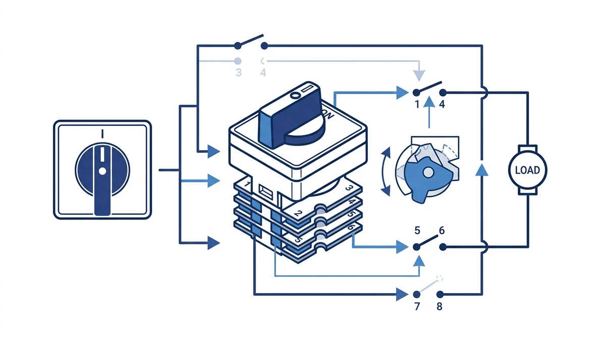
Step 1 — Label the three switch positions: Position 0 (center/off), Position I (Source 1), and Position II (Source 2). These correspond to the cam disc detent stops at 0, 45, and 90 degrees respectively.
Step 2 — Connect Source 1 phase conductors (L1, L2, L3) to input terminals 1, 3, and 5 on the left-side contact block. Neutral, if required, connects to terminal 7.
Step 3 — Connect Source 2 phase conductors to input terminals 2, 4, and 6 on the right-side contact block. Neutral connects to terminal 8.
Step 4 — Connect the common load output terminals to the downstream distribution bus or load circuit. These terminals carry current only when the cam is rotated to Position I or Position II — never simultaneously. That mutual exclusion is enforced by the cam geometry itself, which is the mechanical interlock function.
Step 5 — Torque all terminals to the value marked on the terminal block. For M4 screw terminals, the manufacturer datasheet will specify the correct value; do not substitute a generic figure. Use ferrules on stranded conductors to prevent strand splaying under the screw.
With a continuity tester, confirm that rotating to Position I creates a closed path from the Source 1 input terminals to the load output terminals, while the Source 2 input terminals remain open. Rotating to Position II should reverse this state. Position 0 must show open continuity on all poles. Document the results against the cam diagram before energizing.
For a broader explanation of how changeover switching works at the circuit level, the what is a changeover switch article covers the underlying principles.
The 2-source changeover circuit establishes the general wiring logic. Forward/reverse motor control applies that same cam-switching principle to phase transposition rather than source selection.
The standard forward/reverse wiring uses a 3-position LW28 configuration: Position 0 (center/off), Position F (forward), and Position R (reverse). In the off position, all contacts are open and the motor is de-energized. Rotating to Position F closes contacts that connect L1 to U, L2 to V, and L3 to W at the motor terminals. Rotating to Position R closes a different contact set that swaps the phase connections: L1 to W, L2 to V, and L3 to U. This phase reversal changes motor rotation direction.
For a typical 3-phase induction motor rated at 400V AC, the LW28 contact bridges must carry full load current continuously. The LW28 family covers multiple current frames; suitability for direct motor switching depends on the exact AC-23A rating, motor full-load current, and wiring configuration. Verify the selected part number against the motor nameplate before finalizing the specification.
The wiring sequence at the LW28 terminal block follows this order:
Control panels using this configuration often include a brief off-dwell in the cam profile to prevent direct forward-to-reverse switching under load, which can generate inrush currents well above rated full-load current. The LW28 cam disc geometry can be specified with a center-off detent to enforce this pause — confirm this requirement when ordering.
Forward/Reverse Wiring in Practice
With the wiring sequence confirmed, physical installation is the final step before energizing.
Do not assume a universal cutout for every LW28 configuration; confirm the required panel cutout and mounting depth from the current Shieldhz drawing before machining. Panel material thickness should fall within the range specified in the manufacturer datasheet; panels outside this range may prevent the mounting nut from engaging enough thread to achieve the required clamping force. Deburr the cutout edge before insertion — a sharp edge can nick the gasket and create a leak path that degrades the IP rating over time.
Thread the mounting nut by hand first, then tighten to the torque value specified in the datasheet using a flat-jaw spanner. Under-torquing leaves the switch body free to rotate under repeated actuation. Over-torquing deforms the gasket and can crack the front bezel. For panels installed in high-vibration environments — motor control centers or machine tool cabinets, for example — apply a thread-locking compound rated for the operating temperature range rather than increasing torque beyond the specified limit.
The LW28 achieves IP65 at the panel face when the gasket is undamaged and the cutout tolerance is maintained. The rear of the switch body is not sealed to the same degree, so the enclosure itself must provide the required protection for the terminal block side. If the application demands IP67 or higher, a fully enclosed weatherproof housing is the appropriate solution.
Use ferrules on stranded wire to prevent strand splaying under the screw. Apply a durable circuit-identification label to the front bezel using a label rated for the panel operating temperature. IEC 60447 recommends that position markings be legible and permanently fixed.
Even a correctly installed LW28 will eventually show wear. Knowing how to distinguish between the three main failure categories saves significant diagnostic time in the field.
Intermittent faults are among the most difficult to isolate because they often disappear under static test conditions. Work through these checks in order:
Detent failure means the cam disc does not lock cleanly into a defined position, causing partial contact engagement.
For a systematic wear assessment, IEC 60947-3:2020+AMD1:2025 defines mechanical endurance requirements that provide a useful benchmark. Switches approaching or exceeding their rated cycle count warrant proactive inspection.
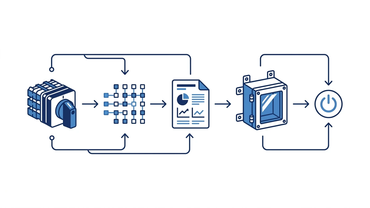
Shieldhz is the export brand of Zhejiang Shihe Electric Co., Ltd., a Zhejiang-based industrial control component manufacturer founded in 2014. For LW28 projects, the practical value is not just supplying a rotary handle and contact blocks. The Shieldhz team checks the operating current, voltage, utilization category, pole count, position sequence, handle style, panel mounting, and enclosure requirement before confirming a buildable model.
For custom LW28 cam programs, buyers should send the source/load diagram, required position labels, motor nameplate data when relevant, panel cutout constraints, and any required certification documents. Shieldhz can then map the contact sequence against the requested function and provide the datasheet, drawing, and documentation package needed for purchasing and panel approval.
A rotary cam switch uses machined cam discs to mechanically encode a unique contact state at each position, allowing multiple independent poles to switch simultaneously in a pre-defined sequence. A standard rotary selector switch typically operates a single common contact across several positions without the multi-pole sequencing capability that cam geometry provides. For applications requiring simultaneous switching of three or more independent circuit paths, the cam switch is the correct choice.
The rated mechanical endurance is defined in the manufacturer datasheet and is governed by IEC 60947-3:2020+AMD1:2025. Switches approaching their rated cycle count should be inspected for contact wear and detent spring condition before continuing in service. Always confirm the specific figure from the Shieldhz datasheet for your part number rather than relying on a generic industry figure.
Yes, for motors where the full-load current and utilization category stay within the exact switch rating shown on the selected LW28 datasheet. Above that threshold, the LW28 should control a contactor rather than carry motor current directly. Always verify against the motor nameplate and the switch datasheet before finalizing the design.
AC-23A is an IEC 60947-3 utilization category covering the switching of motor loads and other highly inductive circuits. It defines the making and breaking capacity the switch must handle, which is more demanding than resistive-load categories like AC-20A. AC-23A is the relevant rating to verify when using the LW28 in motor control or changeover circuits where the load has significant inductance.
Start from the circuit schematic: count the number of independent circuit paths that must switch simultaneously — this gives the pole count — and the number of discrete operating states the panel requires — this gives the position count. Cross-reference against the pole and position selection table in this article to confirm a standard variant covers your application, then contact Shieldhz to confirm availability and request the cam diagram for your chosen configuration before finalizing the order.
The most common causes are silver-alloy contact oxidation from moisture ingress, arc erosion pitting from repeated inductive load switching, and relaxed contact spring preload from thermal cycling. A low-resistance ohmmeter reading significantly above your commissioning baseline at any position is the practical threshold for investigation. If cleaning and re-torquing terminals does not restore baseline resistance, the contact block should be replaced.
The LW28 achieves IP65 at the panel face when correctly installed with an undamaged gasket and a properly toleranced cutout. For fully outdoor installations where the rear of the switch is also exposed to weather, a fully enclosed IP65-rated housing around the entire assembly is the appropriate solution. Confirm the enclosure IP rating against the site environmental classification before specifying.
