PV DC Isolator Pole Count: Choosing 2P, 4P, and Multi-String Configurations
Use a practical buyer checklist to evaluate pv dc isolator pole count inputs, documentation, approval controls and the exact PV DC isolator switch route.
PV DC isolator pole count is a routing decision: decide which DC conductors and strings must be switched, then match that architecture to the exact model wiring diagram, voltage/current data, enclosure, mounting method, and destination-market documentation.
Confirm whether the route is one string, two conductors, multiple strings, or a higher-voltage wiring arrangement that uses more contacts.
Do not select 2P or 4P from pole count alone; check the exact model drawing and datasheet.
Ask for the drawing, datasheet, and certificate package before freezing the panel layout or purchase specification.
What pv dc isolator pole count decides in a PV assembly
Pole count decides how many independent switching contact paths are available for the DC route, not whether the product is suitable by itself. For a buyer, the practical decision is how many PV conductors and string paths must be opened by the selected switch arrangement.
An exact drawing identifies the interfaces that must be controlled for the approved model route.
The pole count is a conductor-routing decision
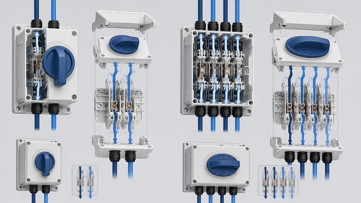
A 2P route commonly starts the discussion for one positive and one negative conductor path. A 4P route gives more contact paths, which may be assigned according to the exact wiring scheme, product drawing, and application requirement.
The important procurement question is not “Is 4P better than 2P?” It is “Which conductors are being switched, and does the selected model documentation show that arrangement?”
The pole count is not the whole specification
Pole count does not independently confirm voltage rating, current rating, enclosure suitability, marking, approval, or destination-market acceptance. Those items depend on the exact model, datasheet, drawing, certificate package, and the buyer’s application.
Use pole count as the architecture filter, then verify the complete switch route before committing panel cut-outs, cable paths, and BOM descriptions.
Choosing 2P or 4P for single-string and dual-conductor routes
Choose 2P when the documented route only needs two switched contact paths, and choose 4P when the documented arrangement requires additional contact paths for the string, voltage route, or layout. The correct choice is the one that matches the manufacturer’s wiring diagram and the buyer’s electrical design.
Sample review should connect the exact item to its current drawing and requested evidence package.
2P as the first commercial shortlist
A 2P option is often the first shortlist when the design has one PV string route and two DC conductors to be switched. It can reduce device size and simplify panel layout when the documented ratings and installation conditions match the project.
However, the buyer should not assume that any 2P model is suitable for every PV string. Maximum DC voltage, current, wiring method, and destination-market requirements must still be checked against the exact documentation.
4P when the route needs more contact paths
A 4P option becomes relevant when the application needs four contact paths, a specific series-contact wiring route, or a multi-conductor arrangement shown in the product documentation. It may also be selected to align with an OEM’s standardized enclosure or harness layout.
The decision should be made from the wiring drawing, not from a generic preference for more poles.
Buyer decision
2P route may fit when
4P route may fit when
What to verify before ordering
One string, two switched conductors
The documented model supports the required voltage/current route
The design standardizes on a 4P body or needs a specified 4-contact arrangement
Exact wiring diagram and datasheet
Higher-voltage route using specified contact arrangement
Only if shown for that model
Often reviewed when the drawing assigns multiple contacts to the route
Model-specific connection diagram
Enclosure space is tight
2P footprint may be easier to place
4P may require more space or different entry planning
Dimension drawing and mounting cut-out
OEM platform standardization
May suit smaller assemblies
May reduce SKU variation if used across several designs
BOM strategy and documentation package
Buyer action checklist
Mark every conductor that must be switched.
Confirm whether the drawing uses one contact path per conductor or a specified multi-contact route.
Check maximum DC voltage and current against the exact datasheet.
Confirm the required operator, mounting style, and enclosure before releasing the panel drawing.
Planning multi-string PV DC isolator pole architecture
For multi-string assemblies, decide first whether each string needs its own switching route or whether the design uses a documented combined route. This decision affects pole count, enclosure size, wiring discipline, service access, and purchasing specification.
Installation conditions change the product-route and document questions a buyer must resolve.
One isolator route per string
A one-route-per-string architecture can make string identification and maintenance planning clearer for an OEM assembly. It may also help when the buyer wants each string path represented separately in the schematic and BOM.
This approach can increase device count, enclosure space, and wiring labor. It should be compared with the buyer’s service concept and the available model range.
Combined multi-string route
A combined route can reduce the number of operators or enclosure cut-outs when the documented product configuration supports the required string arrangement. It can be attractive for repeatable OEM builds where the routing is standardized.
The risk is ambiguity: if the schematic does not clearly assign strings to poles, procurement may buy the wrong configuration. Require the wiring diagram and exact model reference in the purchase specification.
Multi-string decision
Separate route per string
Combined route
Commercial note
String identification
Clearer physical separation
Requires clear labeling and schematic control
Confirm buyer labeling requirements
Enclosure use
More devices or operators may be needed
May reduce cut-outs depending on model
Verify dimensions and cable entry
BOM complexity
More line items or repeated items
Fewer assemblies may be possible
Avoid vague “4P isolator” descriptions
Service concept
String-by-string route can be easier to understand
Depends on documentation and labeling
Match the buyer’s maintenance method
Multi-string routing checklist
Count the number of strings entering the assembly.
Identify whether positive and negative conductors are both switched for each route.
Assign each conductor to a pole path on the schematic.
Compare separate-string and combined-route enclosure layouts.
Confirm the selected model drawing before ordering labels, handles, or enclosures.
Matching pole count with voltage and current documentation
Match pole count to voltage and current only through the exact product documentation. A 2P, 4P, or multi-pole description does not by itself confirm the maximum DC route for a buyer’s application.
Do not infer DC capability from pole count alone
DC switching arrangements are model-specific. Some drawings may show defined contact paths for a stated DC route, while another model with the same pole count may have different limitations or connection instructions.
Procurement should therefore avoid short descriptions such as “4P DC isolator for PV” without the voltage, current, wiring diagram, and model route. That wording can create mismatch between the electrical design and the purchased item.
Keep the electrical limits tied to the part number
The BOM should connect the selected pole count to a specific model, rating reference, and wiring diagram revision where applicable. If the OEM changes string voltage, current, or conductor routing, the isolator route should be rechecked before release.
This is especially important when a panel builder builds several regional variants from a common platform. The same enclosure may need different documentation or markings depending on destination market and buyer requirement.
Enclosure, mounting, operator, and cable-entry effects on pole count
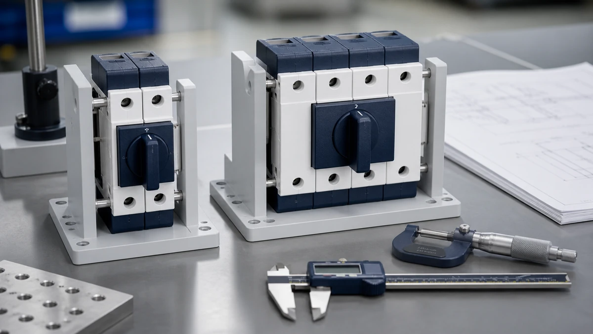
Pole count must be checked against the physical build because extra contact paths can change body size, cable routing, operator position, and enclosure planning. A technically correct schematic can still fail commercially if the selected switch route does not fit the assembly method.
Panel-mounted and enclosed routes
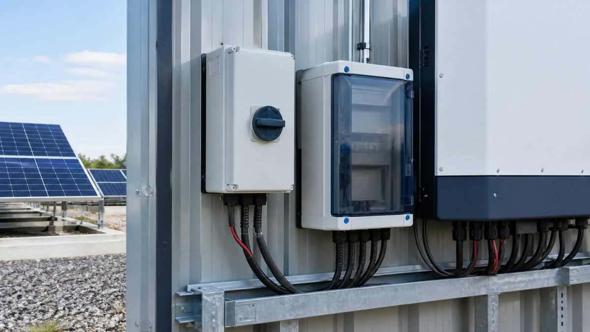
A panel-mounted route may need a specific shaft, handle, mounting depth, and cut-out. An enclosed route may require confirmation of enclosure dimensions, cable entry direction, gland plan, and environmental exposure.
Do not assume the same 2P or 4P core will fit all mechanical options. Ask for the drawing that matches the mounting and enclosure style being purchased.
Operator selection and safety-function limits
Operator color, handle type, padlocking provision, or front-panel style can be important to the buyer’s panel design. These details should be confirmed against the exact model route and drawing.
If an emergency-stop style operator or marking is requested, selecting that operator does not validate a complete machine safety function. The buyer must assess the complete safety function, control architecture, standards, and application requirements separately.
Mechanical verification checklist
Confirm mounting type: panel, enclosure, or other specified arrangement.
Check body depth, shaft length, and handle position.
Verify cable entry direction and conductor bending space.
Confirm label, marking, and operator requirements.
Recheck the drawing after any pole-count or enclosure change.
Shortlisting Shieldhz PV DC isolator switch routes by architecture
Shortlist Shieldhz routes by the pole architecture, wiring diagram, enclosure concept, and document package required by the buyer. The product-family page is useful for range-level navigation, while model-route pages support a more specific commercial review.
Use the range page for initial comparison
Start from the PV DC isolator switch range when the buyer is still comparing product families, installation styles, or commercial options. At this stage, the goal is to narrow the route before requesting exact documentation.
For a 2P, 4P, or multi-string discussion, the range page should not replace model-level verification. Use it to form the shortlist, then confirm the selected route with drawings and datasheets.
Current certificate or approval documentation, where applicable
How Shieldhz confirms a PV DC isolator switch route
Shieldhz confirms a route by matching the buyer’s application inputs to current product documentation before quotation or final selection. Final suitability is confirmed against current product documentation and the buyer’s application.
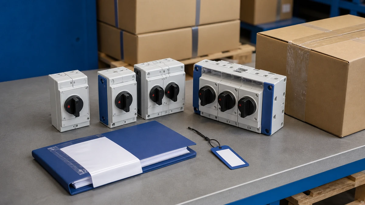
Documentation control, sample acceptance and protective packing are separate handover checks.
Pre-quotation inputs Shieldhz needs
A useful inquiry should include the application and destination market, maximum DC voltage/current, and the string or pole arrangement. It should also state the enclosure or environment, mounting and cable entry requirements, and any requested approval or marking requirement.
If the buyer has a schematic, it should show how each string conductor is assigned to the switch route. If the buyer has not finalized the schematic, Shieldhz can review the intended architecture against available model documentation.
Documentation package for buyer review
Buyers should request the drawing, datasheet, and certificate package needed for their internal approval process. The package available for a route can depend on the exact model, current documentation status, destination market, and buyer application.
A clean quotation request avoids generic wording. Instead of asking for “a 4P PV isolator,” specify the string count, conductor routing, voltage/current, mounting style, enclosure requirement, and documentation expectation.
Pre-quotation confirmation list
Application type and destination market.
Maximum DC voltage and current.
Number of strings and required pole arrangement.
Enclosure, environment, mounting, and cable entry.
Required drawing, datasheet, and certificate package.
Any approval, marking, labeling, or buyer-specific documentation requirement.
Documentation and standards evidence for pole-count decisions
Use documentation to prove the selected route, not broad assumptions about product categories. Standards language can define scope, but buyer approval still depends on the exact product evidence requested for the market and application.
Scope reference without overclaiming
The IEC 60947-3 scope describes this scope as switches, disconnectors, switch-disconnectors and fuse-combination units within stated distribution- and motor-circuit AC/DC limits. That scope statement should not be treated as automatic confirmation that a specific pole count, enclosure, rating, or marking is suitable for every PV build.
For procurement, the practical task is to connect the selected model to the requested datasheet, drawing, and applicable certificate package. If a destination market requires specific markings or approvals, confirm them before issuing the purchase order.
BOM freeze checklist
Before the BOM is frozen, compare the selected route with the PV DC isolator documentation checklist. This helps keep the pole-count decision tied to current evidence rather than informal catalogue descriptions.
BOM release actions
Write the exact model route and pole arrangement in the purchase description.
Attach or reference the current wiring diagram.
Verify maximum DC voltage and current against the datasheet.
Confirm enclosure, mounting, handle, and cable-entry details.
Record the requested certificate or approval package for the destination market.
Reconfirm if string count, voltage, current, or enclosure design changes.
Conclusion
PV DC isolator pole count is a system-routing decision for PV equipment builders and panel OEMs. A 2P route may be suitable when the documented design uses two switched contact paths, while 4P and multi-pole routes become relevant when the wiring diagram, string architecture, or voltage route requires more contact paths.
The reliable buying method is simple: map the conductors, choose the architecture, then verify the exact model documentation. Do not freeze the enclosure, panel cut-out, labels, or purchase specification until the drawing, datasheet, and required document package match the buyer’s application and destination market.
Frequently Asked Questions
Is 4P always better than 2P for a PV DC isolator?
No. A 4P route only makes sense when the wiring architecture, voltage route, or buyer layout requires the additional contact paths and the exact documentation supports that use. A correctly documented 2P route may be the better commercial and mechanical choice for a simpler string path.
Can pole count confirm the DC voltage rating?
No. Pole count alone does not confirm maximum DC voltage. The buyer must verify voltage through the exact model datasheet and wiring diagram.
How should I describe a multi-string isolator requirement in an RFQ?
State the number of strings, which conductors must be switched, the intended pole arrangement, maximum DC voltage/current, enclosure style, mounting method, cable entry, destination market, and document requirements. Avoid vague wording such as “multi-string DC switch” without a schematic or route description.
Can one 4P unit replace two 2P units?
Only if the exact model documentation and the buyer’s design support that route. The decision depends on conductor assignment, string separation needs, ratings, enclosure space, labeling, and service concept.
Do I need separate documentation for different destination markets?
Often, yes. Required certificates, markings, declarations, or approval evidence can vary by market, buyer specification, and exact model. Confirm the required package before quotation or purchase order release.
Does selecting an emergency-style handle make the PV assembly safety compliant?
No. Selecting an emergency-stop style operator or marking does not validate a complete machine safety function. The complete safety function must be assessed separately against the buyer’s machine, control system, standards, and application requirements.
Shi, Muxi
Shi, Muxi writes Shieldhz technical articles for industrial control and electrical component buyers, covering rotary cam switches, isolator switches, PV DC disconnects, push buttons, indicator lights, waterproof enclosures, and terminal blocks. The articles are based on Zhejiang Shihe Electric Co., Ltd.'s manufacturing and export experience, with practical emphasis on model selection, datasheets, drawings, certifications, IP ratings, and inquiry details buyers should confirm before ordering.