Choosing the right rotary cam switch for a control panel comes down to six parameters: load current, switching sequence, pole count, panel cutout dimensions, environmental rating, and certification scope. Get all six right and the switch performs reliably for its full rated service life. Miss one and you face rework, nuisance faults, or a compliance gap at inspection. This guide walks through each parameter in sequence, covers the four most common panel applications, compares leading manufacturers, and closes with a practical wiring walkthrough — giving panel engineers, panel builders, maintenance teams, and OEM buyers a single reference from specification to installation.
A rotary cam switch is a multi-position electromechanical switching device that controls circuit paths by rotating a cam disc against stationary contact carriers. In industrial control panels it serves as a selector switch for motor direction, speed stages, source changeover, or measurement circuits — specified by series and frame, with current Shieldhz routes including LW28 as a broad 10A to 315A cam switch family, LW42 as a compact 20A, 25A, and 32A changeover route, and SH30 as a 20A to 125A isolator route under IEC 60947-3.
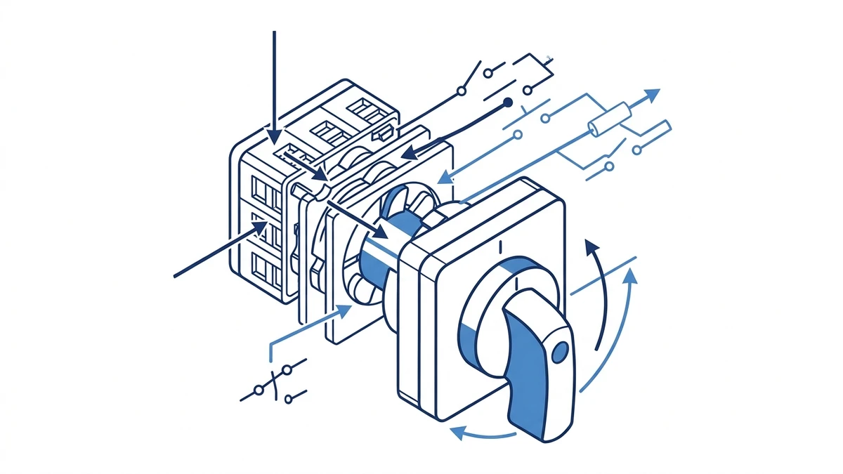
Mechanical Operating Principle
When the actuator shaft turns, precision-machined cam discs rotate in fixed angular steps — commonly 30 degrees, 45 degrees, or 90 degrees per position. Each step engages or disengages specific silver-alloy contact bridges, directing current through pre-defined circuit paths without requiring auxiliary power. This purely mechanical switching action makes rotary cam switches reliable in environments where electronic selectors are vulnerable to electrical noise or voltage transients.
The cam disc profile determines which contacts close or open at each position. As the actuator shaft rotates, lobes on the cam disc push contact bridges against fixed terminals, completing a circuit. When the lobe passes, a return spring lifts the bridge and breaks the circuit. A quality cam mechanism is designed for repeatable indexing and contact wiping, but the exact position tolerance, wiping force, contact material, and expected endurance must be checked against the selected series datasheet. Confirm the exact spring preload and position tolerance values against the product datasheet for your chosen series, as these figures vary by manufacturer and frame size.
Contact material matters significantly. Many industrial switch designs use silver-based contact systems, but the exact material, load rating, and RoHS documentation should be confirmed from the manufacturer datasheet and certificate package for the selected model.
Role in Industrial Control Panels
In motor control centers and machine tool panels, a rotary cam switch typically handles three functions: source selection (transferring load between two supply feeders), motor reversing (swapping two phases to reverse rotation direction), and ammeter or voltmeter selector duty (connecting measuring instruments to different phases in sequence).
For these applications the switch must satisfy IEC 60947-3:2020+AMD1:2025, which applies to switches, disconnectors, switch-disconnectors, and fuse-combination units for distribution and motor circuits, with rated voltage up to 1000 V AC or 1500 V DC. The standard defines making and breaking capacity, mechanical endurance, and rated insulation voltage Ui. The current edition is available directly from the IEC webstore.
A representative panel application places the cam switch on the door face of a 400 V motor control enclosure, where an operator selects between Hand, Off, and Auto modes — a configuration that demands consistent contact wiping action and arc suppression across the full service life of the equipment.
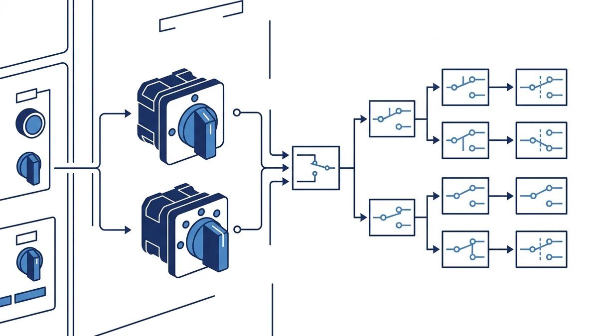
The switching sequence is documented in a contact diagram — a grid showing which contacts are closed (marked with an X) at each rotary position. In a typical 4-position selector switch used for star-delta motor starting, positions 0, 1, 2, and 3 each close a distinct combination of poles, sequencing the motor windings without overlap.
Contact diagrams for the LW28 series and the LW42 series are published per IEC 60947-3 notation, allowing engineers to verify the switching sequence against the panel’s control logic before installation.
Key points when reading a contact diagram in the field:
An X in a cell means the contact is closed at that position; a blank cell means open. Never assume — always verify against the physical switch before energizing.
When a datasheet shows two overlapping X marks across adjacent positions, that is a make-before-break sequence. Confirm this is intentional for your circuit, especially on instrument transformer secondaries where an open circuit creates a voltage spike hazard.
If the contact diagram is missing from a supplier’s datasheet, request it before ordering. A switch without a published diagram cannot be reliably integrated into a panel schematic.
For star-delta sequences, trace each pole individually through all positions before wiring — a single transposed terminal can short two motor windings during the transition step.
If you are new to the device category, the what is a rotary cam switch reference page covers the fundamentals before you work through the selection steps below.
Step-by-Step Selection Criteria for Control Panel Applications
Translating circuit requirements into a specific switch specification follows a repeatable six-step process.
Step 1 — Determine Load Current and Voltage
Start with the circuit’s rated operational current (Ie) and rated insulation voltage (Ui). For AC motor loads, apply utilization category AC-23A, which governs making and breaking of motor currents that can reach multiples of Ie at startup. Common panel ratings fall between 16 A and 63 A at 400 V AC or 690 V AC. Confirm that the switch’s rated making capacity covers the worst-case inrush for your motor frame size — this figure is datasheet-dependent and must be verified per series.
Step 2 — Identify the Switching Sequence
Map the required circuit positions — 2-position, 3-position, or multi-step — against a cam contact diagram. A star-delta starter needs a specific contact-open/close sequence across multiple positions that a generic on-off switch cannot replicate. Modular contact block designs allow cam disc stacking to match complex sequences; confirm the available stack depth against your pole count requirement.
Step 3 — Select Pole Count and Contact Blocks
Count the number of independent circuits to be switched simultaneously. A 3-phase motor isolator typically requires 3 poles minimum; a reversing duty application may need 4 poles to include a neutral or control circuit. Stacked contact blocks add depth behind the panel face — verify available mounting depth before finalizing pole count.
Step 4 — Confirm Panel Cutout and Mounting Depth
Standard actuator diameters are 22 mm or 30 mm. Stacked contact blocks on a 4-pole switch can extend 80 mm to 120 mm behind the panel face depending on the series. Measure available depth in the enclosure before ordering, particularly in compact DIN-rail enclosures where depth is constrained.
Step 5 — Assess Environmental Conditions
For dusty or wet environments, check the enclosure IP rating. A switch mounted in an open panel may only need IP40, while outdoor or washdown locations require IP65 or higher. The IP rating must apply to the complete assembly — switch plus enclosure — not the switch body alone.
Step 6 — Verify Certifications Against Market Requirements
Match the switch’s certification marks to the destination market: IEC 60947-3 for European and international projects, UL 508 for North American panels, and CCC for China. Certification scope matters — confirm the certificate covers the specific current rating and utilization category you selected in Step 1, not just a lower-rated variant of the same product family. Request the test report, not only the declaration of conformity.
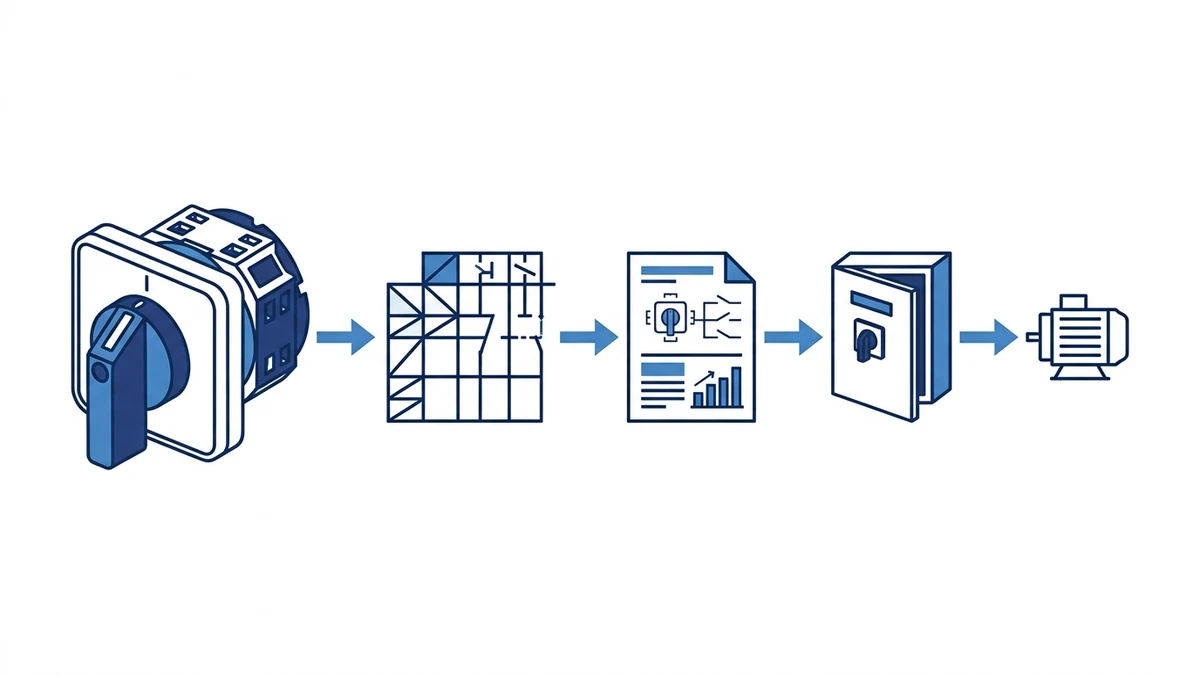
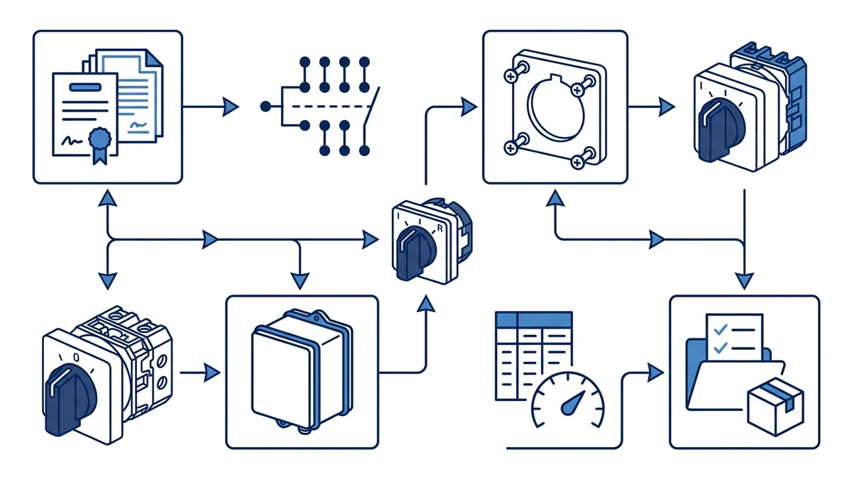
Figure 2. Selection checks should connect the load, switching sequence, enclosure, and documentation requirements.
Common Control Panel Applications and Which Cam Switch Type to Use
Matching the right rotary cam switch to a specific application comes down to three variables: the number of switching positions required, the contact configuration needed, and the current rating of the circuit being controlled.
Application-to-Switch-Type Mapping
Application
Required Positions
Contact Configuration
Recommended Switch Type
Typical Rating
Motor reversing
3 (Forward / Off / Reverse)
4-pole, cross-wired
Multi-position selector, e.g. LW28 series
20 A to 32 A, 400 V AC
Star-delta starting
4 to 5 (Off / Star / Delta / Run)
6-pole or 8-pole
Heavy-duty multi-circuit cam switch, e.g. LW42 series
32 A to 63 A, 690 V AC
Voltmeter selector
4 to 7 positions
2-pole, make-before-break
Instrument selector cam switch
10 A, 500 V AC
Source changeover
3 (Mains / Off / Generator)
4-pole, break-before-make
Isolating cam switch with defined off position
40 A to 63 A, 400 V AC
Key Selection Notes by Application
For motor reversing circuits, the contact wiring must physically swap two phases between the forward and reverse positions. A standard 4-pole cam switch with the correct cam disc sequence handles this without external contactors in smaller drives, typically up to 7.5 kW at 400 V AC. Verify the cross-wiring sequence against the contact diagram before energizing.
Star-delta starting demands the highest contact count of any common application. The switch must open the star connection before closing the delta path — a sequencing requirement that makes cam disc selection critical. IEC 60947-3:2020+AMD1:2025 defines the making and breaking capacity requirements for these utilization categories, and the switch must be rated accordingly.
Voltmeter selector switches operate at low burden currents, so contact rating is rarely the constraint. Position count and make-before-break sequencing matter more to avoid open-circuit voltage spikes on instrument transformers. Confirm the sequence with the instrument transformer manufacturer’s wiring requirements.
Source changeover switches must provide a defined off position between mains and generator to prevent parallel feeding. For outdoor or rooftop generator installations, a weatherproof isolator enclosure is worth considering alongside the switch itself. The what is a changeover switch reference covers the distinction between changeover and isolator duty in more detail.
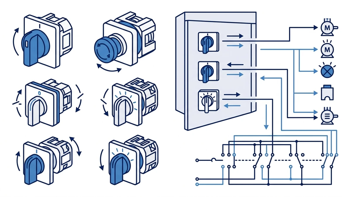
Figure 3. Application wiring context should be verified against the manufacturer contact chart before energizing.
Manufacturer Comparison: Eaton, Kraus and Naimer, Salzer, and ABB
Once you have a specification in hand, comparing manufacturers on the same parameters prevents the common mistake of selecting on brand recognition alone.
Side-by-Side Specification Comparison
Manufacturer
Key Series
Current Range
Pole Options
Certifications
Typical Availability
Eaton
T0, T3, T5
20 A to 160 A
2P, 3P, 4P
IEC 60947-3, UL 508, CE
Global; stocked by major distributors
Kraus and Naimer
CA10, CA20, CG4
10 A to 125 A
1P to 6P
IEC 60947-3, VDE, CE
Strong in Europe; lead times vary elsewhere
Salzer
S40, S41, S200
16 A to 200 A
2P, 3P, 4P
IEC 60947-3, CE, UL (select models)
Asia-Pacific focus; growing global reach
ABB
OC10, OC25, OC63
10 A to 63 A
2P, 3P, 4P
IEC 60947-3, UL 508, CE
Global; integrated into ABB MCC ecosystems
All four manufacturers design to IEC 60947-3:2020+AMD1:2025, which defines rated insulation voltage (Ui), making and breaking capacity, and mechanical endurance. Verify that the specific current rating and utilization category you need are covered by the certificate, not just the product family name.
Key Differentiators to Consider
Kraus and Naimer’s CG4 series supports up to 6-pole configurations, making it a practical choice for complex multi-circuit switching where a single actuator must control several isolated paths simultaneously. Salzer’s S200 series reaches 200 A, covering heavier motor control applications where most competitors top out at 160 A.
For panel builders sourcing across multiple projects, availability and lead time matter as much as specifications. ABB and Eaton carry the broadest global stocking profiles, while Kraus and Naimer units may require longer procurement windows outside Europe.
If your application calls for a cost-competitive alternative with IEC 60947-3 compliance across the 16 A to 63 A range, the LW28, LW42, and SH30 series from Shieldhz cover standard 2P to 4P configurations with CE certification and shorter lead times for OEM and panel builder volumes.
Procurement Pitfalls When Sourcing Cam Switches
Request the full IEC 60947-3 test report, not just the CE declaration of conformity. The declaration is self-issued; the test report shows which ratings were actually verified by a third-party lab.
Check that the certificate number on the product label matches the document the supplier provides. Counterfeit switches frequently carry copied certificate numbers that resolve to a different product or manufacturer when verified with the issuing body.
For multi-project panel builds, lock in a single series across the project rather than mixing pole configurations from different manufacturers — terminal layouts and contact diagram notation differ enough to cause wiring errors under time pressure.
When evaluating lead times, ask specifically about the pole count and current rating you need, not the product family in general. A 4-pole 63 A variant may be made-to-order even when the 3-pole 32 A version ships from stock.
Wiring a Rotary Cam Switch in a Control Panel: Practical Walkthrough
Correct wiring is where a well-specified switch either performs as designed or becomes a recurring fault. The steps below close that gap.
Step 1: Identify Terminals Before Connecting Anything
Cam switches use a numbered terminal grid printed on the contact block housing. Terminals are typically arranged in pairs: odd numbers on the input side, even numbers on the output side. Cross-reference the switch’s contact diagram — supplied in the datasheet — against your circuit schematic before touching any conductor. For a standard 3-position, 3-pole switch, you will typically work with 12 terminals across four contact layers. Confirm the terminal numbering convention for your specific series, as it varies between manufacturers.
Step 2: Prepare and Insert Conductors
Strip conductors to the manufacturer’s specified strip length, generally 8 mm to 10 mm for screw-clamp terminals. Use ferrules on stranded wire to prevent strand splaying under the screw. Insert one conductor per terminal unless the terminal is explicitly rated for two conductors — check the datasheet, not a general reference.
Step 3: Torque Terminal Screws to Specification
Under-torqued connections cause resistive heating; over-torqued screws crack the terminal block. For most cam switches in the 16 A to 63 A range, terminal torque is specified between 1.2 Nm and 2.5 Nm, but this range is datasheet-dependent. Always use a calibrated torque screwdriver and verify the value against the product datasheet for your specific series and terminal size.
Step 4: Verify Switching Sequence Under No Load
Before energizing, rotate through all switch positions and use a continuity tester to confirm each contact opens and closes per the contact diagram. This catches miswired positions before they become live faults. Document the verification result as part of the panel’s commissioning record.
Common Wiring Mistakes to Avoid
Connecting load-side conductors to input terminals, which reverses breaking duty
Mixing control voltage and power circuits in the same terminal row
Skipping ferrules on flexible cable, which causes strand migration over time
Ignoring the cam switch’s utilization category — AC-21A, AC-22A, or AC-23A — when sizing wire cross-section
Failing to re-torque terminals after the first thermal cycle in service
Figure 4. A complete inquiry should include rating, contact sequence, mounting, enclosure, and document requirements.
Where to Source Certified Rotary Cam Switches for Your Panel Build
Sourcing certified rotary cam switches from a verified supplier is the final — and often overlooked — step in panel design. The wrong source can deliver switches that pass visual inspection but fail IEC 60947-3 compliance under load, creating liability exposure and rework costs that far exceed the original component price.
Datasheet Checklist Before You Order
Before committing to any supplier, confirm these parameters on the product datasheet:
Rated insulation voltage (Ui) at or above the circuit voltage, with 690 V AC as the practical minimum for industrial panels
Rated operational current at the correct utilization category (AC-23A for motor loads, AC-22A for mixed resistive and inductive)
Mechanical endurance rating, typically 20,000 to 50,000 operating cycles depending on series and frame size
IP rating matching your enclosure environment
Contact material specified (AgSnO2 or AgCdO for switching duty)
If any of these are absent from the datasheet, treat that as a disqualifying gap and request the information before ordering.
Certification Marks to Verify
Accepted certification marks for panel-grade rotary cam switches include CE (EU Low Voltage Directive), CCC (China Compulsory Certification), and UL listing where North American codes apply. Ask suppliers for test reports, not just logos — certification marks printed on packaging without traceable documentation carry no compliance value. Cross-reference the certificate number against the issuing body’s online registry to confirm it resolves to the exact manufacturer, product series, and rated parameters you are purchasing.
Lead Time and Supply Chain Considerations
Standard catalog switches in common pole configurations (2-pole, 3-pole, 4-pole) typically ship within 3 to 7 business days from stocked inventory. Custom cam sequences or non-standard handle configurations generally require 2 to 4 weeks of production lead time. Build that buffer into your panel schedule, particularly for first-article builds where a specification change may require a different cam disc stack.
Shieldhz, operating as Zhejiang Shihe Electric Co., Ltd., offers the LW28, LW42, and SH30 series with full IEC 60947-3 documentation, stocked configurations, and direct technical support for OEM and panel builder volumes. Browse the complete rotary cam switch range to confirm specifications for your application before ordering.
How Shieldhz Turns Selection Notes Into a Buildable Part Number
Shieldhz is not only matching a keyword such as rotary cam switch to a catalog family. In a real order, the team converts the buyer’s selection notes into a part number, contact sequence, handle choice, and documentation package. That review normally covers circuit function, rated current, voltage, utilization category, number of positions, pole count, terminal marking, mounting format, enclosure condition, and certification references.
For the fastest confirmation, send a one-line circuit description, the load or motor nameplate, desired switch positions, any existing panel cutout drawing, and the target market’s documentation needs. Shieldhz can then decide whether LW28, LW42, SH30, or an enclosed route is the cleaner fit and return a datasheet-backed recommendation instead of a loose catalog suggestion.
Frequently Asked Questions
What is the difference between AC-21A, AC-22A, and AC-23A utilization categories?
These IEC 60947-3 categories define the severity of the switching duty. AC-21A covers resistive loads with slight inductive content. AC-22A covers mixed resistive and inductive loads including small motor loads. AC-23A covers motor loads where inrush current can reach significant multiples of the rated operational current at startup. Selecting the wrong category means the switch may be undersized for the actual breaking demand, leading to accelerated contact wear or failure.
Can a rotary cam switch be used as a motor isolator?
Yes, provided the switch carries an appropriate IEC 60947-3 rating for the motor’s full-load current and utilization category, and the contact configuration includes all live conductors — typically 3-pole for a 3-phase motor. It must also provide a clearly defined off position that isolates the motor from the supply. Check whether the product is classified as a switch-disconnector under IEC 60947-3, as that classification carries specific isolation requirements beyond a standard selector switch.
How many operating cycles should a cam switch be rated for?
IEC 60947-3 sets minimum mechanical endurance requirements for switch-disconnectors, and quality-grade cam switches are commonly rated to 20,000 to 50,000 cycles depending on the series and frame size. For high-frequency selector duty — such as an ammeter selector switched multiple times per shift — confirm the mechanical endurance figure against your expected annual cycle count and calculate the projected service interval accordingly.
What causes contact resistance to increase over time in a cam switch?
The primary causes are oxidation on contact surfaces from insufficient wiping action, arcing damage from repeated switching above the rated breaking capacity, and loose terminal connections that create resistive heating. Specifying AgSnO2 contacts and ensuring the switch operates within its rated utilization category significantly slows contact degradation. Periodic torque checks on terminal screws during scheduled maintenance also help prevent resistive heating from loosening over thermal cycles.
Is a rotary cam switch the same as a rotary isolator?
They overlap in function but differ in design intent. A rotary isolator is specifically designed to provide safe electrical isolation with a visible off position and often carries additional requirements for padlocking and isolation distance. A rotary cam switch is optimized for multi-position switching sequences and may or may not meet full isolator requirements — check the product’s IEC 60947-3 classification before using it as an isolator. The what is a load isolator switch reference covers the distinction in more detail.
What IP rating do I need for an outdoor cam switch installation?
IP65 is the practical minimum for outdoor enclosures, providing full dust exclusion and protection against water jets from any direction. For coastal, washdown, or submersion-risk environments, IP66 or IP67 is more appropriate. The IP rating must apply to the complete assembly — switch plus enclosure — not the switch body alone. Verify the IP rating of the assembled unit, not just the switch housing, before specifying for outdoor use.
How do I verify that a cam switch certificate is genuine?
Cross-reference the certificate number printed on the product or datasheet against the issuing certification body’s online registry — CB Scheme, TUV, or the relevant national body. A genuine certificate will resolve to the exact manufacturer, product series, and rated parameters. If the number returns no result or resolves to a different product, treat the certification as unverified and request clarification from the supplier before proceeding with the order.