A DC switch disconnector is a manually operated switching device used to separate a direct-current circuit from its source or load. In solar PV, battery, EV charging, telecom power, and DC control circuits, it gives technicians a defined OFF position so equipment can be isolated, inspected, serviced, or shut down according to the site procedure.
The term often appears beside related phrases such as DC isolator, PV DC isolator, load break switch, DC disconnect switch, and switch-disconnector. These phrases overlap, but they are not always identical in rating or use. The key selection question is whether the device is declared for the DC voltage, current, pole arrangement, operating duty, enclosure exposure, and certification route required by the project.
This guide explains the practical meaning of a DC switch disconnector, how it differs from AC switching, where it is used in solar systems, and what buyers should confirm before specifying one.
What a DC switch disconnector does
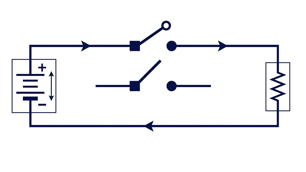
A DC switch disconnector opens and closes a direct-current circuit by moving internal contacts through a handle, rotary mechanism, or enclosed switch assembly. In the OFF position, the switch creates a separated contact path so downstream equipment can be isolated for service, testing, replacement, or emergency operation.
The OFF position separates the DC source from the downstream load or equipment section.
For a buyer, the useful definition is simple: a DC switch disconnector is selected when a DC circuit needs manual disconnection and a clear switching state. The device may be installed inside a cabinet, in a weatherproof enclosure, near a solar inverter, beside a battery cabinet, or at a field-accessible point in an outdoor DC system.
It is not the same as a fuse, surge protective device, or automatic circuit breaker. A disconnector is normally chosen for manual switching and isolation. Protective devices are selected for overcurrent, short-circuit, surge, or residual-current functions. Some assemblies combine more than one function, but the datasheet should state exactly what the device is intended to do.
Why DC switching is harder than AC switching
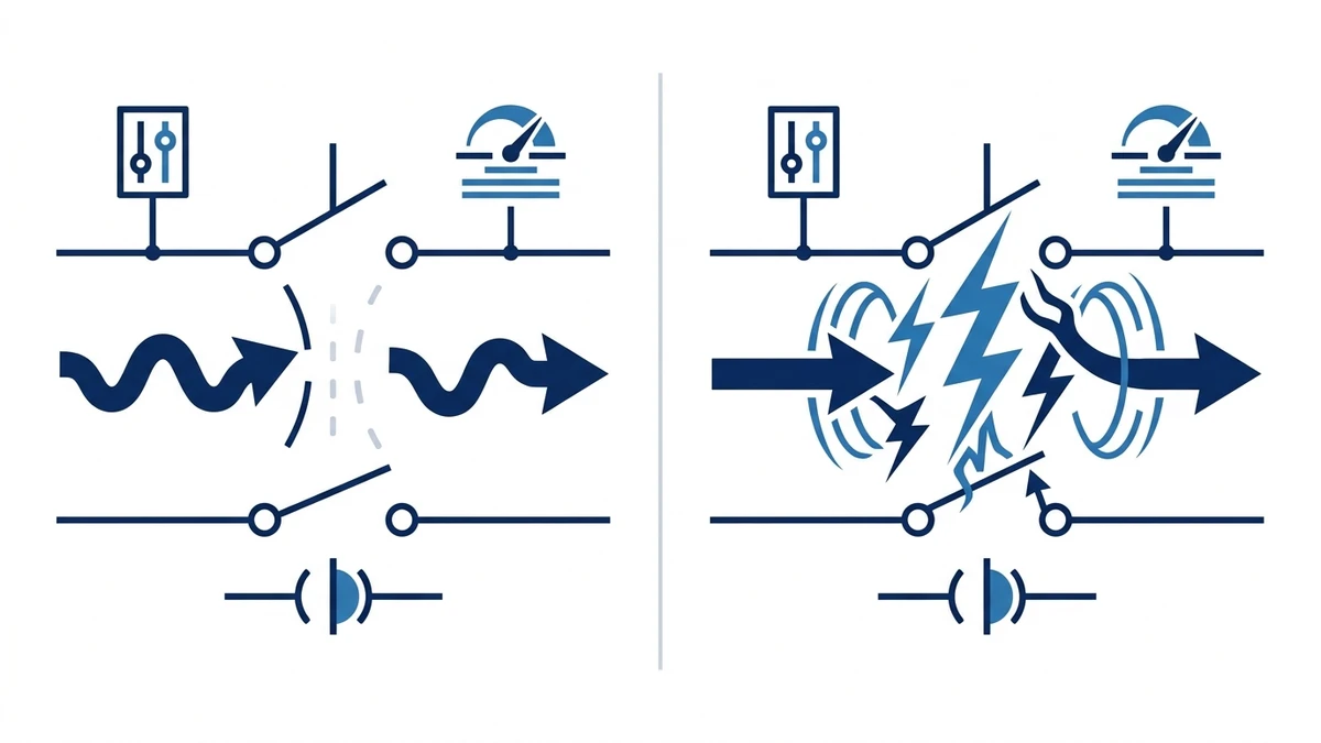
Direct current does not cross zero the way alternating current does. That means an arc created while opening contacts can last longer and can be harder to extinguish. If the switch is not rated for the DC circuit, the result can be contact wear, overheating, welding, insulation damage, or a failed open position.
This is why DC switch disconnectors are not selected by ampere rating alone. A device marked for a certain AC current cannot automatically be used in a DC circuit at the same current. The contact spacing, arc path, switching speed, terminal layout, and pole configuration all affect DC performance.
Standards such as IEC 60947-3 are commonly used as a technical reference for low-voltage switch-disconnectors and related switching equipment. The final rule set for a specific installation still comes from local electrical codes, system design documents, equipment manuals, and the declared rating of the exact switch model.
AC switch vs. DC switch disconnector
Selection point
AC switch
DC switch disconnector
Arc behavior
Helped by natural current zero crossing
Needs DC-rated contact and arc control design
Voltage check
AC voltage rating may be enough for AC circuits
DC voltage rating should match corrected circuit voltage
Common use
Motors, lighting, general AC panels
Solar strings, battery circuits, DC cabinets, EV auxiliary circuits
Spec risk
Underrating mainly shows under load or fault
Wrong DC rating can cause persistent arcing or contact damage
Main types and construction
DC switch disconnectors come in several formats: open DIN-rail switch bodies, panel-mounted rotary switch disconnectors, enclosed outdoor isolator boxes, fused disconnectors, and multi-pole assemblies for higher voltage or multi-string wiring.
DC switch disconnector construction should match the declared voltage, current, and operating duty.
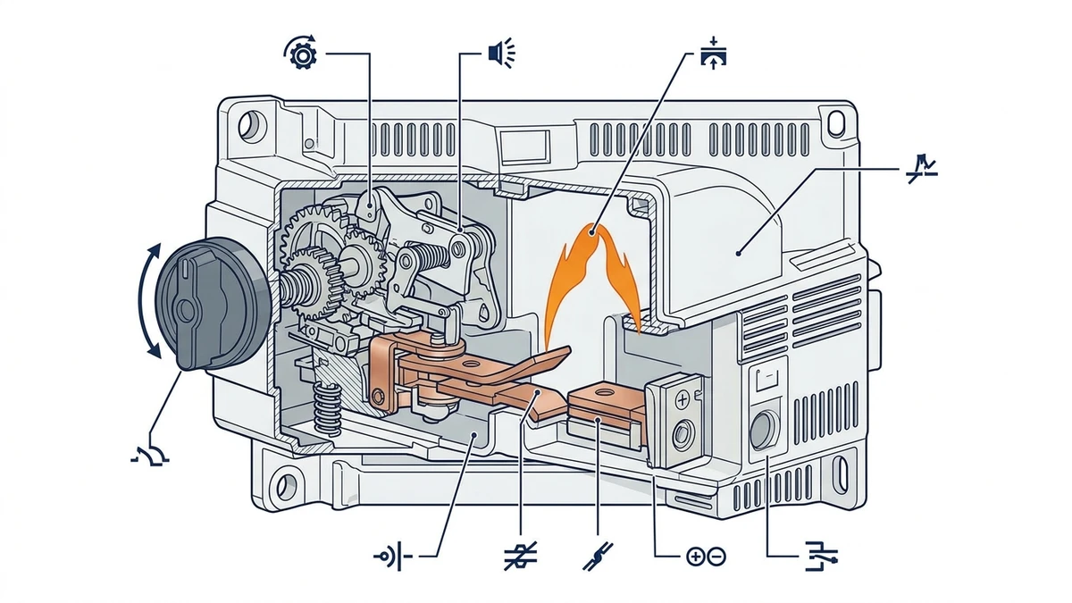
The basic parts are similar across designs. The handle or actuator gives the operator an ON/OFF interface. The mechanism opens the contacts with a defined movement. The terminals accept the conductor size and wiring direction. The enclosure protects the switch from touch, dust, moisture, UV exposure, and mechanical impact. Labels and lockout features support maintenance work.
Fused vs. non-fused DC disconnectors
A non-fused DC switch disconnector provides manual separation where protection is handled elsewhere in the system. A fused disconnector adds fuse holders so selected DC branches can be isolated and protected in one assembly. In solar combiner or battery circuits, the fused route can simplify service, but it also changes heat, replacement, and coordination considerations.
The choice depends on the circuit design. Buyers should confirm whether string fuses, branch protection, inverter-side protection, or battery protection are already specified before choosing a fused switch body.
Where DC switch disconnectors are used
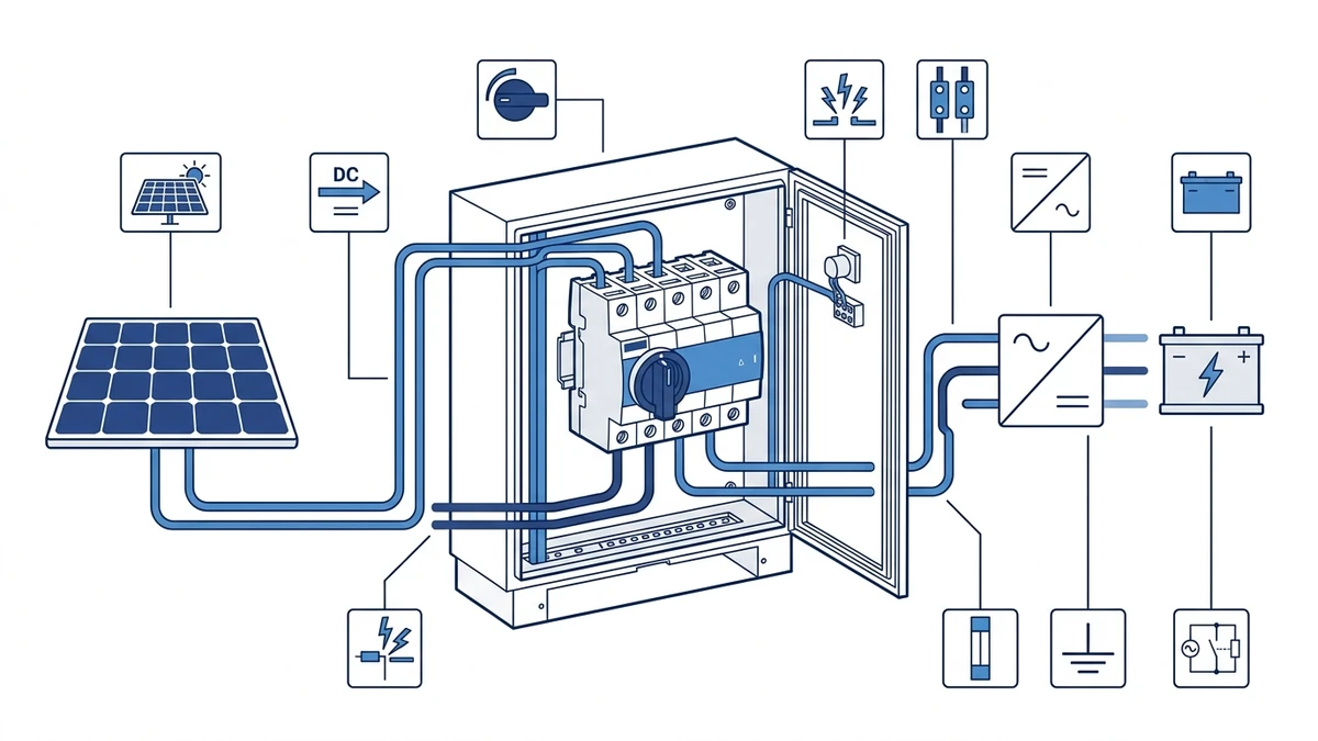
DC switch disconnectors are common wherever a direct-current source remains present during operation. Solar PV is the most visible example because panels can keep producing voltage in daylight, even when the inverter is stopped. Battery energy storage, DC power distribution, telecom backup power, EV charging auxiliary systems, and industrial DC control panels can also use manual DC isolation points.
For solar PV specifically, a DC switch disconnector may sit between the PV string and inverter input, between a combiner and inverter, inside a DC distribution cabinet, or inside an outdoor isolator enclosure. A buyer comparing PV products can start with the Shieldhz PV DC isolator switch range and then narrow by voltage, current, pole count, enclosure, and certification route.
The previous foundation article, What Is a PV DC Isolator Switch?, explains the solar string use case in more detail. This article uses the broader switch-disconnector term because the same engineering logic appears in several DC systems, not only rooftop PV.
Load switching and isolation are not the same question
Many buyers ask whether a DC switch disconnector can be opened under load. The answer depends on the declared utilization category, voltage/current rating, system design, and operating procedure. Some devices are selected primarily for isolation after load has already been reduced or stopped. Others are rated for specific load-break duties. The datasheet should make that difference clear.
Isolation and load switching should be checked against the exact declared device rating.
In practical terms, “disconnecting” means separating the circuit. “Load switching” means making or breaking current under defined operating conditions. A switch disconnector may be suitable for both within its rating, but it should not be assumed. In solar PV, the array can remain energized whenever illuminated, so the operating procedure should match the inverter manual and the switch rating.
Questions to ask before load switching
Question
Why it matters
What is the maximum DC voltage?
DC arc behavior depends strongly on voltage
What current is present when switching?
Load current changes contact stress and heat
Is the switch declared for load break duty?
Isolation-only use is different from frequent switching
Are multiple poles wired in series?
Pole configuration can affect voltage handling
Is there a required shutdown sequence?
Inverter, battery, or controller procedure may reduce stress
How to select a DC switch disconnector
Start with the circuit, not the catalogue photo. The voltage rating should cover the maximum expected DC voltage. The current rating should cover the design current and operating duty. The number of poles should match the wiring design. The enclosure should match the environment. The terminal design should fit the conductor size, cable entry, bend radius, and installation method.
DC switch disconnector selection should start from the circuit voltage, current, duty, and environment.
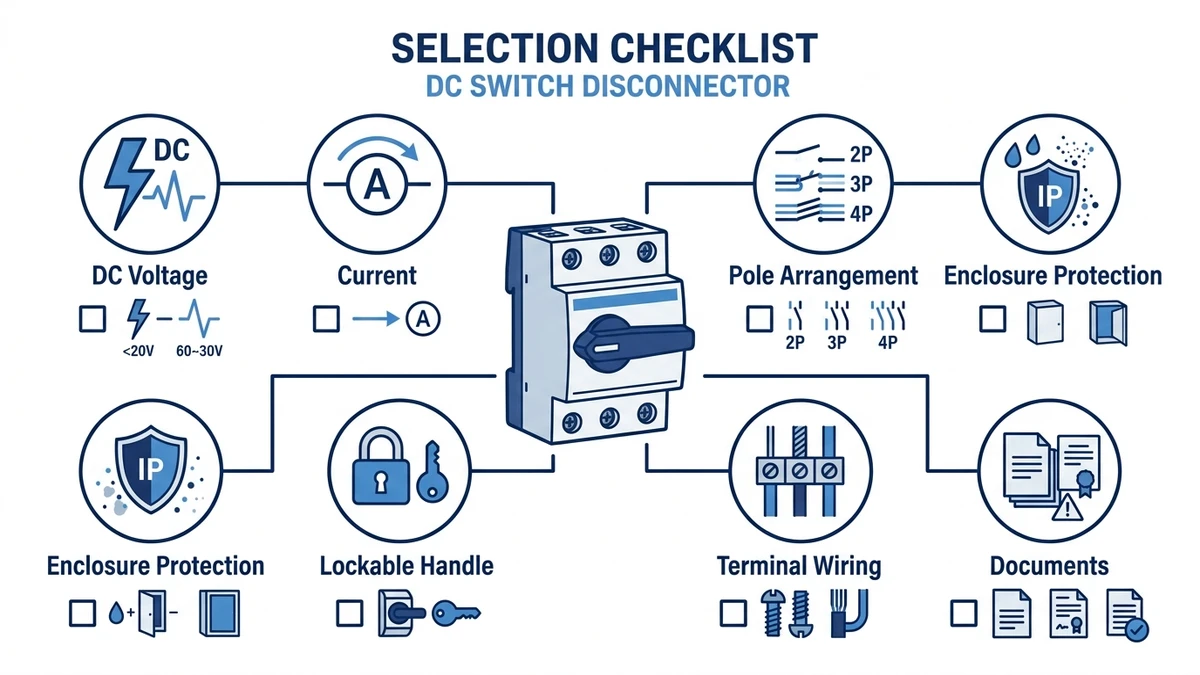
Use this checklist for procurement:
Item
What to confirm
DC voltage rating
Corrected open-circuit or maximum system voltage
DC current rating
Operating current and declared duty for the application
Pole arrangement
Positive, negative, series pole wiring, or multi-circuit switching
Enclosure/IP route
Cabinet, indoor room, rooftop, outdoor, dusty, humid, or washdown area
Locking/position indication
OFF position visibility and lockout expectations
Terminals and wiring
Cable size, torque, glands, MC4 or terminal options where applicable
Documents
Datasheet, wiring diagram, approvals, and installation instructions
A DC switch disconnector should be installed by competent personnel using the product datasheet, system drawing, torque requirements, and local electrical rules. Many field problems are not caused by the switch concept itself; they come from loose terminals, poor cable gland sealing, wrong wiring direction, water ingress, UV degradation, or a rating mismatch.
During inspection, look for discoloration around terminals, a hot enclosure surface, cracked plastic, difficult handle movement, damaged glands, water marks, missing labels, or unusual odor. If any of these appear, the safer route is to isolate according to the site procedure and review the device before continued operation.
For outdoor solar use, enclosure quality and cable entry are especially important. A high-quality switch can still fail early if water tracks through the gland, if cable tension distorts the enclosure, or if the switch is placed where standing water or direct mechanical impact is likely.
Shieldhz product-line context
Shieldhz manufactures industrial switching and control components for panel builders, solar PV installers, OEMs, and distributors. In the DC switch-disconnector area, the practical product fit is usually PV DC isolation, outdoor DC isolator enclosure routes, and related switching products for solar and industrial control systems.
The right Shieldhz route depends on project data. Send the system voltage, current, number of strings, pole configuration, enclosure expectation, cable-entry requirement, quantity, and target market documentation. If the project is solar PV, include the inverter model, string design, and whether the switch will be cabinet-mounted or installed outdoors.
For project support, use the Shieldhz contact page with the circuit data and expected certification route. A cleaner specification at the start reduces rework during quotation, sampling, and installation review.
FAQ
What is a DC switch disconnector used for?
A DC switch disconnector is used to manually separate a direct-current circuit from its source or load. Common applications include solar PV strings, battery systems, DC power cabinets, telecom power, EV auxiliary circuits, and industrial DC control panels.
Is a DC switch disconnector the same as a DC isolator?
The terms overlap, especially in solar PV product language, but the exact function depends on the device rating and datasheet. A DC isolator emphasizes manual isolation, while switch-disconnector language may also point to declared switching duty under defined conditions.
Can a DC switch disconnector be opened under load?
Only if the exact device is rated and selected for the intended load-switching duty. Some installations use a disconnector after the load has been reduced or stopped, while others require a load-break-rated DC switch. Confirm the declared rating before operation.
Why can I not use an AC switch for DC isolation?
DC arcs do not extinguish naturally at a zero crossing, so an AC-only switch may not safely interrupt the same voltage or current on a DC circuit. The switch should have a declared DC voltage/current rating and contact design suited to the application.
What voltage rating should a DC switch disconnector have?
The rating should cover the maximum expected DC voltage in the circuit. In solar PV, this usually means checking the module open-circuit voltage, string count, temperature correction, and inverter input design before choosing the switch.
What is the difference between a DC switch disconnector and a DC circuit breaker?
A DC switch disconnector is mainly a manual switching and isolation device. A DC circuit breaker is selected for automatic overcurrent or fault interruption. Some systems use both, but they should not be treated as interchangeable without engineering review.
What information should I send when asking for a quotation?
Send the DC voltage, current, number of poles, application type, indoor or outdoor mounting, enclosure/IP expectation, cable-entry route, required documents, quantity, and target market. For solar PV, also include string count and inverter input details.
Shi, Muxi
Shi, Muxi writes Shieldhz technical articles for industrial control and electrical component buyers, covering rotary cam switches, isolator switches, PV DC disconnects, push buttons, indicator lights, waterproof enclosures, and terminal blocks. The articles are based on Zhejiang Shihe Electric Co., Ltd.'s manufacturing and export experience, with practical emphasis on model selection, datasheets, drawings, certifications, IP ratings, and inquiry details buyers should confirm before ordering.