A selector switch is a manually operated control device that lets an operator choose between fixed circuit states, such as ON/OFF, AUTO/MANUAL, LOCAL/REMOTE, or FORWARD/OFF/REVERSE. The key idea is selection. Instead of giving a short command and returning to its rest position, a maintained selector switch stays in the chosen position until the operator turns it again.
Selector switches are common in industrial control panels because they give operators a visible, repeatable way to set machine mode. They are used beside push buttons, indicator lights, emergency stops, PLC input modules, motor starters, and control relays. In a well-designed panel, the selector switch position should tell the operator what state the circuit is meant to hold.
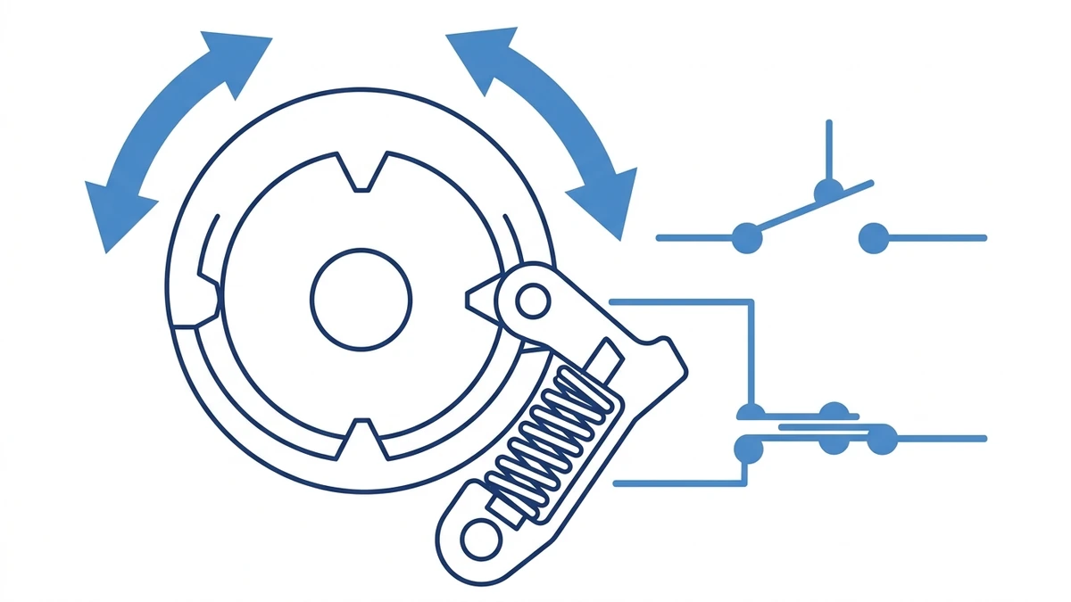
A maintained selector switch uses mechanical detents to hold the selected circuit state.
What Is a Selector Switch?
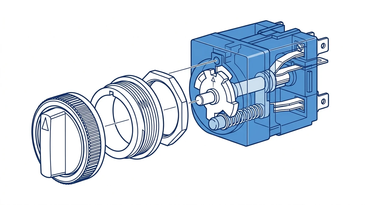
A selector switch is a multi-position operator switch with one actuator and one or more contact blocks. When the actuator is rotated, internal contacts open or close according to the selected position. The actuator may be a short knob, long handle, key cylinder, illuminated selector, or multi-position cam-style handle.
Most panel selector switches are built around common mounting sizes such as 22 mm or 25 mm, which lets them fit the same control station layout as many industrial push buttons and signal lamps. In the Shieldhz product context, selector switches sit in the same practical panel family as push buttons, metal operators, waterproof control stations, and indicator lights.
The simplest example is a 2-position maintained selector switch:
Position
Contact State
Typical Meaning
Left or 0
Contact open
OFF, stopped, disabled, local off
Right or 1
Contact closed
ON, enabled, auto, remote command
A 3-position selector switch adds a center position. That center position is often used as OFF, STOP, or NEUTRAL, while the left and right positions select two different operating modes.
Maintained Action: Why the Switch Holds Position
“Maintained” means the switch remains in its last selected position after the operator releases it. This behavior is normally created by a mechanical detent. As the shaft rotates, a spring-loaded part engages with shaped notches in the actuator or cam. Each notch gives the operator a tactile stop and keeps the shaft from floating between positions.
The electrical part follows the mechanical position. A contact block behind the actuator contains normally open or normally closed contacts. When the shaft reaches a defined angle, a cam or plunger changes the contact state. The contact remains in that state because the actuator remains locked in the selected position.
This makes a selector switch different from a momentary push button. A momentary push button gives a command only while it is pressed. A maintained selector switch holds a circuit instruction continuously. For a practical comparison of operator behavior, see the Shieldhz guide on what a push button switch is.
Not every selector switch is maintained. Some selector switches are spring-return types. For example, a 3-position switch may stay in the center position but spring back from the left or right command position. Always check the product description, contact chart, and actuator action before ordering.
Common Selector Switch Types
Selector switches look similar from the front of a panel, but their internal action and circuit logic can be very different. The most common types are below.
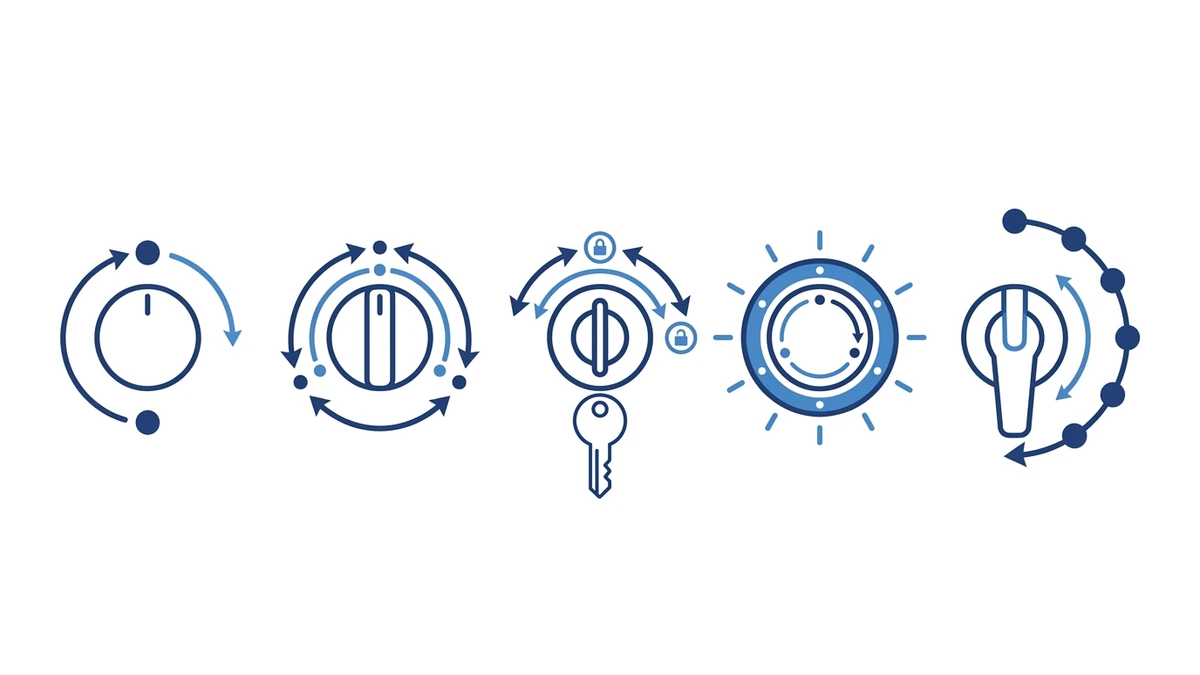
Selector switches may use knobs, keys, illuminated heads, or cam-style handles depending on the panel function.
2-Position Selector Switch
A 2-position selector switch has two stable states. It is used for simple decisions such as ON/OFF, HAND/AUTO, MANUAL/AUTO, LOCAL/REMOTE, or ENABLE/DISABLE. The contact block may be normally open, normally closed, or a combination of both.
3-Position Selector Switch
A 3-position selector switch has left, center, and right positions. The center position is often OFF or neutral. This layout is common for motor direction, pump mode selection, and control source selection. Depending on the application, the switch may be maintained in all three positions or spring-return from one or both side positions.
Key Selector Switch
A key selector switch restricts operation to authorized personnel. The key may be removable in one position, multiple positions, or only when the circuit is off. This is useful for maintenance mode, reset authorization, test mode, and equipment that should not be changed by a casual operator.
Illuminated Selector Switch
An illuminated selector switch combines position selection with visual feedback. The lamp may show that control power is present, that the selected mode is active, or that a circuit state has been confirmed by another device. For separate status indication, Shieldhz also publishes a practical guide on what an indicator light is.
Multi-Position Cam Selector
When a control task needs more positions or more complex contact sequences, the selector function may move into a rotary cam switch. A cam switch can coordinate several circuits through one shaft and is often used for changeover, voltmeter selection, motor control, and staged control logic. For higher-current or multi-circuit selection, compare the application with rotary cam switches.
Type
Typical Positions
Typical Use
Key Selection Point
2-position maintained
2
ON/OFF, MANUAL/AUTO
Contact state in each position
3-position maintained
3
LOCAL/OFF/REMOTE, FWD/OFF/REV
Center position meaning
Spring-return selector
2 or 3
Jog, reset, command pulse
Which side returns automatically
Key selector
2 or 3
Access control, maintenance mode
Key removal position
Illuminated selector
2 or 3
Mode selection plus visual status
Lamp voltage and circuit logic
How Selector Switch Contacts Are Wired
A selector switch does not usually carry the main load current of a machine. In most modern control panels, it sends a control signal to a contactor coil, relay, PLC input, drive input, or control module. The controlled device then handles the power circuit.
The contact chart determines how each selector position is interpreted by the control circuit.
The most important document is the contact chart. It shows which terminals are connected in each switch position. A 3-position selector switch may look simple from the outside, but the contact chart determines whether the switch is suitable for HAND/OFF/AUTO, LOCAL/OFF/REMOTE, or another control scheme.
A common HAND/OFF/AUTO example works like this:
Selector Position
Contact Path
Control Result
HAND
Manual contact closes
Operator command runs the load through the control circuit
OFF
Both command contacts open
Load cannot be started from hand or auto path
AUTO
Auto contact closes
PLC, float switch, timer, or controller can run the load
For PLC input wiring, one side of the selector contact normally connects to a control supply or input common, and the other side goes to a digital input. The PLC program then interprets the input as a mode request. The exact wiring depends on the control voltage, sinking or sourcing input type, safety architecture, and machine standard.
For relay or contactor circuits, the selector switch may be wired in series with coil control power. In that case, the contact rating must match the coil voltage and the type of load being switched. Inductive loads are harder on contacts than simple resistive signals, especially in DC circuits.
Selector Switch vs Push Button, Indicator Light, and Cam Switch
Selector switches are often confused with other panel devices because they share the same mounting space. The difference is the job each device performs.
Device
Main Function
Operator Action
Typical Circuit Role
Push button
Send a command
Press and release
Start, stop, reset, jog
Selector switch
Choose and hold a mode
Rotate to a position
Auto/manual, local/remote, off/on
Indicator light
Display status
No switching action
Power, run, fault, trip, ready
Rotary cam switch
Switch multiple paths or higher current
Rotate through positions
Changeover, motor control, source selection
In panel design, these devices usually work together. A selector switch chooses the operating mode, a push button starts or resets the process, and an indicator light confirms status. The choice should not be based only on appearance. It should be based on whether the circuit needs a pulse command, a held mode, a status signal, or a multi-circuit switching sequence.
Where Selector Switches Are Used
Selector switches appear wherever an operator must choose a stable control mode. Typical applications include:
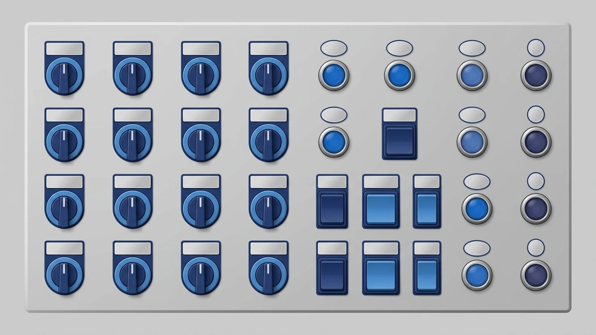
Selector switches give operators a visible, held mode selection on industrial control panels.
Application
Selector Function
Practical Reason
Pump panel
HAND/OFF/AUTO
Allows manual run, safe off, or controller operation
HVAC control panel
LOCAL/REMOTE
Chooses panel control or building automation control
Machine tool
MODE selection
Separates setup, manual, and automatic operation
Conveyor system
FORWARD/OFF/REVERSE
Selects direction through control logic
Test bench
SOURCE selection
Routes a control signal or measurement path
Outdoor control station
ON/OFF or AUTO/MANUAL
Gives visible mode selection near the equipment
From field use, the best selector switch layouts are simple enough to understand without opening the panel. The handle position, legend plate, and machine response should agree. Confusing legends are a real commissioning problem because a correct wiring diagram does not help much if the operator can misread the panel face.
How to Choose a Selector Switch
Start with the function, not the appearance. A selector switch is a small component, but a wrong selection can make the control circuit awkward, unsafe, or hard to troubleshoot.
1. Define the positions
Write the intended positions in order, such as OFF/ON, MANUAL/AUTO, LOCAL/OFF/REMOTE, or FORWARD/OFF/REVERSE. Confirm whether the center position is a safe off state or an active mode.
2. Choose maintained or spring-return action
Use maintained action when the circuit must hold a selected mode. Use spring-return action when the operator should issue a temporary command, such as reset, jog, or test.
3. Match the contact arrangement
Check whether the switch needs normally open contacts, normally closed contacts, or both. For more complex control, confirm the complete contact chart position by position. Do not assume that two switches with the same front actuator have the same back-of-panel logic.
4. Check voltage, current, and load category
Selector switch contacts should be rated for the actual control circuit. A low-current PLC input is different from an AC relay coil or a DC solenoid circuit. For low-voltage control circuit devices, IEC 60947-5-1 is the relevant standard family; the IEC 60947-5-1 publication page is a useful authority reference when checking the standard scope.
5. Confirm mounting diameter and panel environment
Confirm the cutout diameter, panel thickness, locking nut style, and contact block depth. For dusty, wet, or outdoor panels, choose a suitable front protection rating and enclosure design. The front operator, gasket, enclosure, cable entry, and installation quality all affect real ingress protection.
6. Specify actuator and legend
Choose short knob, long handle, key, illuminated head, or guarded layout based on how the operator will use the panel. Then define the legend text before production. Clear legends reduce commissioning errors and make maintenance checks faster.
7. Confirm documentation
For purchasing and panel assembly, request the contact diagram, mounting dimensions, rated operational voltage and current, IP rating, certificate information where required, and wiring terminal details. For project-specific operator stations or product matching, contact Shieldhz with the position sequence, control voltage, mounting size, and panel environment.
Field Checks and Common Mistakes
One common mistake is using a maintained selector switch where the control system expects a momentary command. The machine then stays in a command state longer than intended. The opposite mistake also happens: a spring-return selector is installed where the operator expects the mode to remain selected.
Another mistake is ordering by front appearance only. Two selector switches can share the same knob and still have different contact blocks behind the panel. Always verify the contact chart before replacing a part.
In maintenance, check that the switch turns crisply between positions, the legend remains readable, terminals are tight, and the actuator does not feel loose. If contacts are worn, heat-damaged, or unreliable, replacement is usually better than trying to repair the contact surface in the field.
Frequently Asked Questions
What is a selector switch used for?
A selector switch is used to choose a stable operating mode in a control circuit. Common examples include ON/OFF, MANUAL/AUTO, LOCAL/REMOTE, HAND/OFF/AUTO, and FORWARD/OFF/REVERSE.
What does maintained selector switch mean?
A maintained selector switch holds its selected position after the operator releases it. The internal detent keeps the actuator in place, and the contacts remain in the selected open or closed state.
What is the difference between a selector switch and a push button?
A push button usually sends a short command when pressed. A selector switch chooses a position and holds that circuit state until the operator changes it again.
How does a 3-position selector switch work?
A 3-position selector switch has left, center, and right positions. Each position has a defined contact state. The center position is often OFF or neutral, while the side positions select two different modes or commands.
Is a selector switch the same as a cam switch?
Not exactly. A selector switch is usually a control-circuit operator for mode selection. A cam switch is a rotary switching device that can handle more complex contact sequences and, depending on design, higher-current switching duties.
Can a selector switch be wired to a PLC input?
Yes. Selector switches are often wired to PLC digital inputs so the controller can read selected modes such as AUTO, MANUAL, LOCAL, or REMOTE. The wiring must match the PLC input type and control voltage.
What IP rating should a selector switch have outdoors?
Outdoor use depends on the complete installation. The operator head, panel enclosure, gasket, cable entries, and mounting surface all matter. For wet or dusty locations, specify a suitable IP-rated operator and enclosure rather than relying on the switch head alone.
Final Takeaway
A selector switch is a small panel component with a large effect on how a machine is operated. The right choice starts with the required positions, then the action type, contact logic, rating, mounting size, and environment. For pre-launch panel planning, define the mode sequence early, verify the contact chart, and match the selector switch to the control circuit instead of selecting by knob style alone.
Shi, Muxi
Shi, Muxi writes Shieldhz technical articles for industrial control and electrical component buyers, covering rotary cam switches, isolator switches, PV DC disconnects, push buttons, indicator lights, waterproof enclosures, and terminal blocks. The articles are based on Zhejiang Shihe Electric Co., Ltd.'s manufacturing and export experience, with practical emphasis on model selection, datasheets, drawings, certifications, IP ratings, and inquiry details buyers should confirm before ordering.