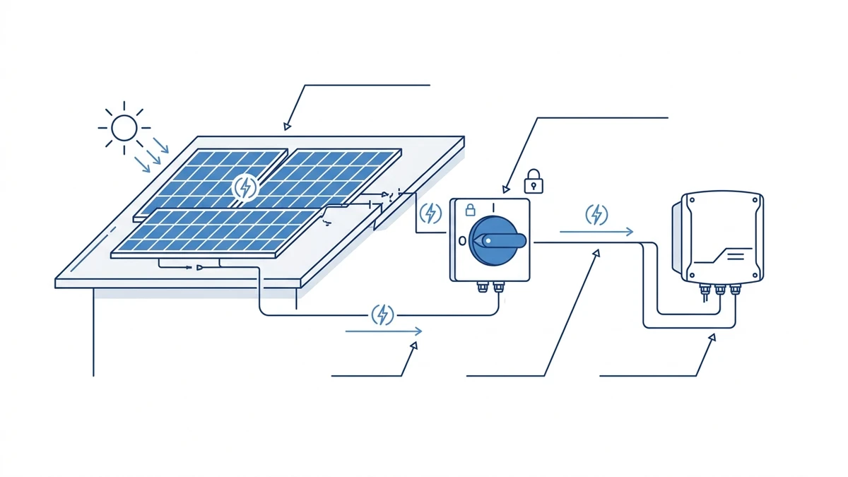
A PV DC isolator switch is a manually operated disconnect device used on the direct-current side of a solar photovoltaic system. It separates the PV string, combiner, or inverter input from the live DC source so installers and maintenance teams can inspect, service, or shut down part of the system with a defined open position.
In plain terms, the switch gives the solar DC circuit a controlled off point. That sounds simple, but PV DC isolation is more demanding than ordinary AC disconnection because solar modules keep producing voltage whenever they receive light, and DC arcs do not naturally pass through a zero-current crossing. The isolator therefore has to match the system voltage, current, pole arrangement, enclosure exposure, and the installation rules used for that project.
For Shieldhz, PV DC isolators sit inside the wider industrial control component family: switching, isolation, enclosure protection, and field-service safety. This article explains the basics before a buyer moves into detailed product comparison.
What a PV DC isolator switch does
A PV DC isolator switch provides manual separation between solar panels and downstream equipment such as a string inverter, combiner box, or DC input circuit. Its job is to create a repeatable OFF state with a contact gap suitable for the rated DC circuit, so the equipment side can be treated as isolated according to the site’s safety procedure.
A PV DC isolator gives the solar string circuit a defined manual OFF point before downstream equipment.
The important point is that a PV DC isolator is not just a convenient on/off handle. It is selected as part of the electrical safety architecture. When the switch is opened correctly, it helps maintenance staff identify the isolated circuit, lock or secure the handle where required, test for absence of voltage on the intended side, and avoid accidental reconnection during work.
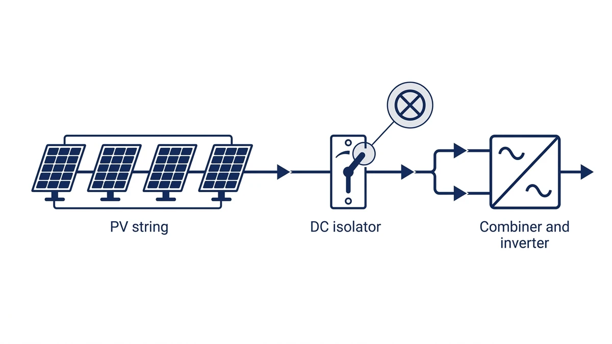
A typical PV string path looks like this:
PV circuit point
What the isolator supports
Module string output
Separates one string or string group from downstream equipment
Combiner box
Allows grouped strings to be isolated before inverter input
Inverter DC input
Gives a local manual disconnect point near the inverter
Outdoor rooftop or field enclosure
Provides a weather-resistant operator interface when the switch is installed outside
For product routing, Shieldhz groups these products under its PV DC isolator switch range, where series choice depends on the voltage/current rating, enclosure, and application route.
Why DC isolation is different from AC isolation
AC circuits pass through a current zero point many times per second. That zero crossing helps extinguish an arc when contacts open. DC circuits do not behave that way. If the contacts separate under unsuitable conditions, the arc can persist, heat the contacts, damage the enclosure, or create a fire risk.
That is why a switch used on the DC side of a solar installation should be a DC-rated isolator, not an ordinary AC disconnect selected only by current value. The switch mechanism, contact spacing, arc path, and terminal design need to be suitable for the declared DC rating. A 32 A AC switch is not automatically a 32 A PV DC isolator.
Selection should start from the system’s maximum open-circuit voltage, the expected short-circuit current, the number of strings, and the exact wiring arrangement. For compliance language, treat standards such as IEC 60947-3 as the technical reference point for low-voltage switch-disconnectors, while the final installation requirements still come from local code, project documentation, and the equipment datasheet.
Common PV DC ratings to confirm
The most common buyer mistake is checking only the ampere rating. For solar DC circuits, the voltage rating is just as important. A rooftop string can have a high open-circuit voltage on a cold bright morning, and the isolator should still remain within its declared rating.
Confirm these values before selecting a device:
Rating item
Why it matters
Rated DC voltage
Should cover the maximum PV string open-circuit voltage after temperature correction
Rated current
Should cover the design current for the string or string group
Pole configuration
Should match whether positive, negative, or multiple circuits are switched
Utilization/category marking
Indicates the type of DC switching duty declared by the manufacturer
Enclosure/IP rating
Should match indoor, outdoor, rooftop, dusty, humid, or washdown exposure
Main parts of a PV DC isolator switch
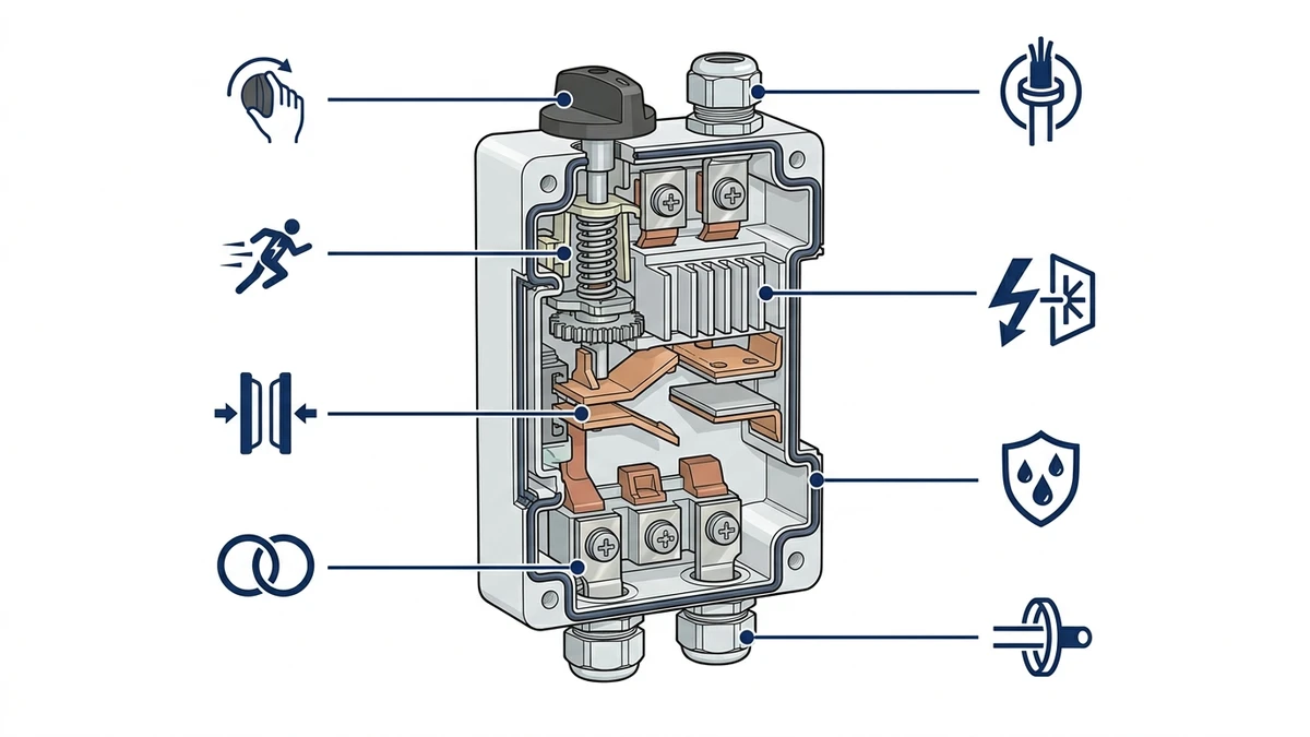
A PV DC isolator is built around a small number of practical parts: the operator handle, switch mechanism, contact system, terminals, enclosure, cable glands, and labeling. These parts are simple to name, but each one affects field reliability.
DC-rated contact design helps manage arc behavior when the PV circuit is isolated correctly.
The handle gives the installer a clear ON/OFF interface. For maintenance work, the handle may also provide a lockable OFF position, depending on the model and local lockout procedure. The internal mechanism translates handle movement into fast contact opening and closing. The contact system creates the actual electrical separation and needs to be designed for DC arc behavior.
The enclosure matters heavily in PV because many isolators are mounted outdoors. UV exposure, rain, heat cycling, dust, cable-entry sealing, and installer workmanship all affect long-term performance. For exposed rooftop work, IP65 or IP66 is often used as a practical starting point, but the correct rating should be confirmed against the project environment and installation standard.
Fused and non-fused versions
Non-fused PV DC isolators are used when the circuit already has the planned protection elsewhere and the main purpose is manual isolation. Fused isolators combine isolation with fuse protection for selected string or combiner applications. Neither route is universally correct. The system design decides whether fuses are needed, where they should sit, and how accessible they should be for replacement.
For example, Shieldhz’s GF40 PV DC isolator switch route is useful when buyers are comparing compact PV DC isolation options by voltage/current rating and enclosure format.
Where PV DC isolators are installed in a solar system
PV DC isolators are commonly installed close to the inverter DC input, near a combiner box, or at a field-accessible point on the array side. Some systems use more than one isolation point so different maintenance tasks can be performed without treating the entire PV array as one undifferentiated circuit.
The right placement depends on the inverter type, array layout, roof access, cable route, combiner location, local electrical rules, and emergency or maintenance procedures. A residential rooftop system may have fewer isolation points than a commercial multi-string system with combiners and long cable runs.
String-level vs. array-level isolation
String-level isolation separates one string or small string group. This can make troubleshooting easier because a technician can work on one branch while identifying where a fault is located. Array-level isolation separates a larger group of PV modules before the inverter or combiner output. It is simpler, but it gives less granularity.
In procurement terms, the practical question is not “how many isolators does every solar system need?” It is “which parts of this system should be separately isolated for installation, maintenance, troubleshooting, and emergency operation under the local rules?”
How to operate and test a PV DC isolator
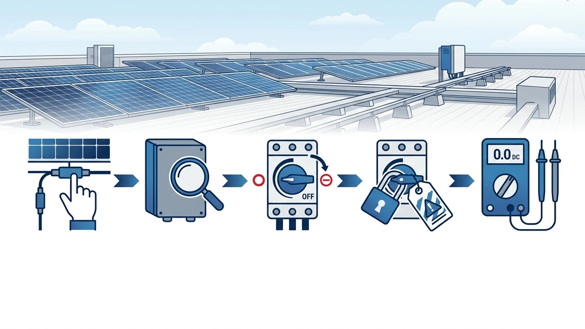
A PV DC isolator should be operated according to the inverter manual, project method statement, and site safety procedure. The usual field logic is simple: identify the correct circuit, stop or reduce load where the procedure requires it, operate the isolator to OFF, secure the handle if lockout is required, then test the intended side with the correct meter before touching conductors.
Safe PV isolation practice combines correct circuit identification, OFF operation, lockout when required, and voltage verification.
The most important step is verification. A handle in the OFF position is not the same as proof that every conductor in the work area is de-energized. PV modules can still produce DC voltage when illuminated, and stored energy may exist in inverter input circuits. Competent personnel should confirm the actual condition of the circuit before work begins.
Practical field checklist
Step
What to confirm
Identify
Match the isolator label to the inverter, string, combiner, or array section
Inspect
Check enclosure cracks, water marks, loose glands, heat discoloration, and damaged labels
Operate
Turn the handle fully to OFF without forcing a stiff mechanism
Secure
Apply lockout or tagging where the site procedure requires it
Test
Verify voltage on the intended side with a suitable DC-rated meter
Record
Note faults, replacement needs, or abnormal heating for maintenance follow-up
This kind of field procedure is where E-E-A-T matters in content: selection advice should match how installers actually work with live solar DC equipment, not just a catalogue table.
Common faults and maintenance signs
PV DC isolator failures are often linked to heat, moisture, UV degradation, incorrect cable entry, loose terminations, unsuitable ratings, or operation outside the intended duty. Outdoor enclosures deserve special attention because small installation defects can become water-ingress problems over time.
Look for these warning signs during inspection:
Symptom
Possible cause
Practical response
Brown marks near terminals
Loose termination, overheating, or overload
Isolate, inspect torque and cable condition, replace damaged parts
Stiff or loose handle
Mechanism wear, contamination, or enclosure distortion
Do not force operation; investigate before reuse
Cracked housing
UV aging, impact, or unsuitable enclosure material
Replace enclosure/switch assembly as required
Moisture inside box
Gland sealing, lid gasket, or mounting orientation issue
Correct sealing route and assess internal corrosion
Repeated nuisance damage
Wrong rating, bad placement, or harsh environment
Review specification, mounting, and enclosure protection
Maintenance intervals should be set by the site owner or installer based on environment and risk. Rooftop, coastal, high-temperature, dusty, or high-UV installations usually justify closer inspection than clean indoor inverter rooms.
How to choose a PV DC isolator switch
The best selection workflow starts with the system design, not the switch catalogue. First calculate the maximum PV string voltage at the lowest expected module temperature. Then confirm the current, pole arrangement, enclosure, installation position, lockout needs, certification documentation, and cable-entry route.
PV DC isolator selection should start from the system design, not only the ampere rating.
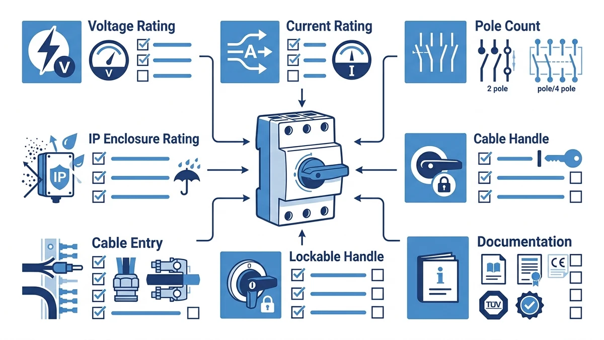
Use this as a buying checklist:
Selection item
Better question to ask
Voltage rating
Is the DC rating above the corrected maximum string Voc?
Current rating
Does the device cover the circuit current and operating duty?
Pole count
Are all required conductors switched according to the wiring design?
Enclosure
Is the IP rating and material suitable for the mounting location?
Cable entry
Can glands, bend radius, and conductor size be installed cleanly?
Locking
Does the handle support the site’s lockout practice?
Documents
Are datasheets, certificates, and wiring diagrams available for review?
Shieldhz manufactures industrial control components for panel builders, solar PV installers, OEMs, and electrical distributors. The PV DC isolator range is part of a broader switching and isolation portfolio that also includes cam switches, AC isolator switch routes, push buttons, indicator lights, and terminal accessories.
The practical Shieldhz value is not a generic “one switch fits all” message. It is product matching: compact PV DC isolation for small and mid-size systems, weather-resistant enclosures for outdoor mounting, clear handle operation, and documentation support for buyers who need to compare specifications before ordering.
Zhejiang Shihe Electric Co., Ltd. was founded in 2014 and operates manufacturing capacity in Zhejiang, China. The company serves export markets across Europe, Australia, Southeast Asia, and other regions, with product documentation and certification support varying by series and project requirement. For a project review, send the string voltage/current, pole requirement, installation location, enclosure expectation, and target certification route through the Shieldhz contact page.
FAQ
What is the difference between a PV DC isolator and an AC isolator?
A PV DC isolator is designed and rated for direct-current solar circuits, where arcs do not naturally extinguish at a zero crossing. An AC isolator may have the same current number on the label, but that does not make it suitable for PV DC service unless the datasheet explicitly declares the needed DC rating and duty.
Can I use a normal AC disconnect switch for solar panels?
Do not assume so. Solar strings require DC-rated switching equipment selected for the calculated voltage, current, contact arrangement, and installation environment. Using an AC-only device on a PV DC circuit can create arc and overheating risks.
How many PV DC isolators does a solar system need?
It depends on the inverter design, number of strings, combiner layout, cable routing, maintenance access, and local installation rules. A simple system may need only limited isolation points, while a commercial multi-string system may use several isolators for string, combiner, or inverter-side separation.
Does a PV DC isolator need to be lockable?
Many projects prefer or require a lockable OFF position for maintenance lockout, but the exact requirement should be checked against local rules and the site safety procedure. In procurement, it is safer to confirm lockout needs before ordering the switch enclosure.
What IP rating should an outdoor PV DC isolator have?
Outdoor PV isolators are commonly selected from weather-resistant IP-rated enclosures such as IP65 or IP66, but there is no single universal answer. Confirm the mounting exposure, cable-entry sealing, UV exposure, dust, rain, washdown, and local installation requirement.
What voltage rating should I choose for a PV DC isolator?
Choose a rating above the calculated maximum open-circuit voltage of the PV string after temperature correction. The exact value should come from the module datasheet, series string count, lowest expected ambient temperature, inverter design, and the isolator datasheet.
Is a PV DC isolator the same as a DC circuit breaker?
No. A PV DC isolator is primarily a manual isolation device. A DC circuit breaker is selected for automatic protection and fault interruption. Some systems use both, but they are specified for different functions and should not be treated as interchangeable without engineering review.
Shi, Muxi
Shi, Muxi writes Shieldhz technical articles for industrial control and electrical component buyers, covering rotary cam switches, isolator switches, PV DC disconnects, push buttons, indicator lights, waterproof enclosures, and terminal blocks. The articles are based on Zhejiang Shihe Electric Co., Ltd.'s manufacturing and export experience, with practical emphasis on model selection, datasheets, drawings, certifications, IP ratings, and inquiry details buyers should confirm before ordering.