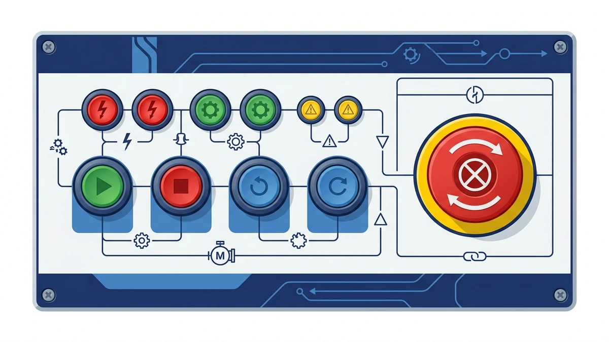
A push button switch is a manually operated control device that changes an electrical contact state when an operator presses an actuator. In industrial panels, it is used to start, stop, reset, jog, enable, signal, or interrupt a control circuit. The button itself is simple to operate, but the correct specification depends on contact type, actuator action, electrical rating, mounting size, environment, and panel logic.
In most control panels, the push button is the point where a human command enters the electrical system. Pressing the actuator may close a normally open contact, open a normally closed contact, illuminate a pilot light, or trigger a relay or PLC input. Because the device is touched repeatedly by operators, it should be easy to identify, mechanically reliable, and matched to the circuit it controls.
This foundation guide explains what a push button switch does, how NO and NC contacts work, how momentary and maintained actions differ, and what buyers should confirm before selecting a panel-mounted model.
What a push button switch does
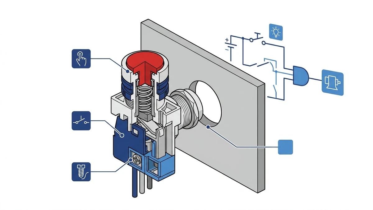
A push button switch converts a physical press into a defined electrical state change. When the actuator moves, it drives a plunger or contact mechanism inside the switch body. That movement either connects or separates the contact terminals, depending on the contact block fitted behind the panel.
Internal actuator movement changes the contact state behind the panel.
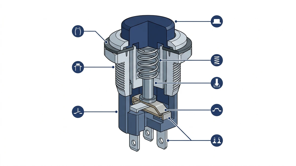
The basic assembly usually includes the actuator head, mounting collar, panel seal, contact block, terminals, and sometimes an LED module. The visible front part is only one piece of the system. The contact block behind the panel decides what the control circuit actually does.
For general product routing, Shieldhz groups these devices under its push button switch and indicator light range, where buyers can compare plastic, metal, illuminated, and indicator-related panel components.
Core components
Component
Practical role
Actuator head
The visible button surface pressed by the operator
Mounting collar or nut
Secures the device to the panel cutout
Contact block
Provides NO, NC, or combined contact logic
Terminal screws or clamps
Connect the device to field wiring
Front seal
Helps protect the panel opening from dust or moisture
LED module
Adds illumination or status indication when specified
The switch should not be selected only by color or front appearance. The rear contact arrangement, wiring method, and ratings decide whether the part fits the control circuit.
Normally open and normally closed contacts
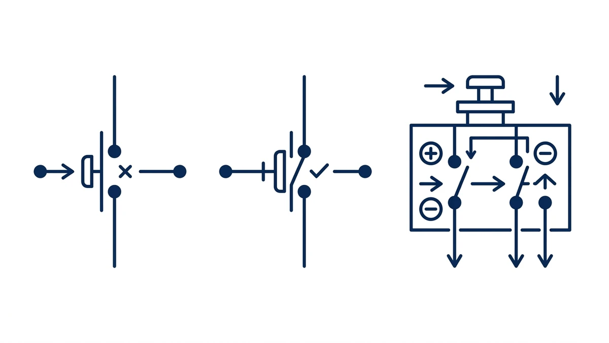
The most important concept in push button switch selection is contact state. A normally open contact, often written as NO, is open when the button is not pressed. Pressing the actuator closes the circuit. A normally closed contact, or NC, is closed at rest and opens when the actuator is pressed.
NO, NC, and combined contact blocks create different control circuit logic.
NO contacts are common for start, reset, jog, and signal inputs. NC contacts are common for stop commands, interlocks, and circuits where opening the circuit is the desired action. A combined NO + NC contact block lets one button change two circuits at the same time.
Contact logic examples
Contact type
Resting state
Pressed state
Common use
NO
Circuit open
Circuit closed
Start, reset, PLC input, jog
NC
Circuit closed
Circuit open
Stop, interlock, permissive signal
NO + NC
One open, one closed
Both change state
Control logic, mode feedback, interlock routing
In a motor control panel, a green start button often uses a momentary NO contact. A red stop button commonly uses an NC contact so pressing it opens the control path. The exact logic should always be confirmed against the panel schematic rather than assumed from button color alone.
Momentary, maintained, and illuminated actions
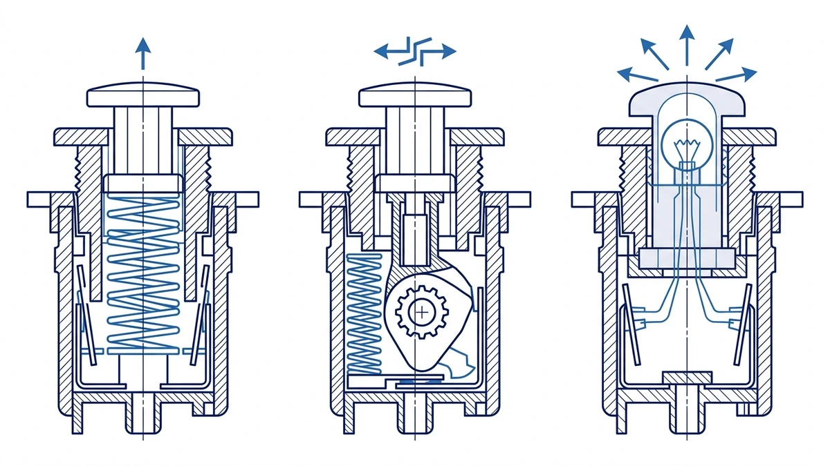
Push button switches are also classified by actuator action. A momentary push button returns to its original state when the operator releases it. A maintained push button holds its changed state until it is pressed again or reset by another action. An illuminated push button adds a light source inside the actuator cap so the button can also communicate status.
Momentary, maintained, and illuminated actuators suit different operator commands.
Momentary action is common for start, reset, and jog commands because the circuit only needs a short pulse. Maintained action is used when the switch should physically hold an on/off or selected state. Illuminated action is useful when operators need status feedback at the same panel position, especially in compact operator stations.
Provides a larger target for stop or urgent actions
Key-operated
Limits operation to authorized staff
Illuminated
Combines command and status indication
Emergency-stop functions require separate safety review. Do not treat any large red mushroom button as a compliant emergency stop unless the full device, contact logic, reset behavior, color scheme, safety circuit, and applicable machine-safety standard have been checked.
Electrical and environmental ratings
A push button switch may look small, but it still needs ratings that match the control circuit. Buyers should confirm rated voltage, rated operational current, utilization category, insulation rating, contact material, terminal capacity, mechanical endurance, and environmental protection.
For standards context, IEC 60947-5-1 is the relevant low-voltage switchgear and controlgear standard for control circuit devices and switching elements. The exact rating, however, comes from the product datasheet for the selected model.
Ratings to confirm
Rating item
Why it matters
Control voltage
Should match the PLC, relay, contactor coil, or signal circuit
Rated operational current
Depends on load type and AC/DC duty
Utilization category
Helps distinguish resistive and electromagnetic load switching
Contact material
Affects low-current signal reliability and contact wear
IP rating
Matches dust, splash, outdoor, or washdown exposure
Mechanical life
Indicates expected actuation durability under test conditions
For indoor electrical cabinets, a lower front protection rating may be enough. For outdoor panels, dusty production areas, wet pump stations, or washdown locations, higher ingress protection may be specified. IP65 or IP67 can be useful starting points, but the correct value depends on the enclosure, gasket, panel finish, cable entry, cleaning method, and project rules.
Panel mounting and wiring basics
Most industrial push button switches are mounted through a circular panel cutout. Common sizes include 16 mm, 22 mm, 25 mm, and 30 mm, depending on the product family and market. A 22 mm cutout is widely used in industrial control panels, but buyers should always verify the exact datasheet before drilling.
The installation sequence is straightforward: mark the panel, cut the hole cleanly, remove burrs, seat the front gasket, insert the actuator, tighten the mounting collar, attach the contact block, and wire the terminals according to the drawing. Problems often come from poor cutout quality, over-tightening, incorrect contact block orientation, or mixed-up NO/NC terminals.
Field checklist
Step
What to check
Cutout
Diameter, edge quality, and spacing from adjacent devices
Panel thickness
Whether the mounting thread and collar fit the enclosure
Seal
Whether the gasket sits flat with no trapped burrs or paint chips
Contact block
Correct NO, NC, or combined arrangement
Wiring
Terminal label, conductor size, ferrule, and torque route
Test
Continuity, actuation feel, indicator function, and panel label
From a field-maintenance point of view, it is worth recording the contact arrangement and wire numbers before the panel is energized. This helps later troubleshooting when a start command, stop command, or PLC input fails intermittently.
Common panel uses
Push button switches appear in nearly every operator interface panel because they are predictable, compact, and easy to understand. The same basic device can serve many roles depending on contact logic and actuator style.
Push button switch selection should follow the exact panel command and contact logic.
Common examples include motor start/stop stations, pump panels, conveyor jog controls, machine reset buttons, hoist control stations, HVAC panels, process control desks, and test benches. In some panels, the push button works with an indicator light so the operator can see whether a command has been accepted or whether the circuit is energized.
Application examples
Application
Common button logic
Motor start
Momentary NO contact into control relay or PLC input
Motor stop
NC contact opening a control path
Reset after fault
Momentary NO signal to PLC or controller
Jog or inching
Momentary hold-to-run operation
Pump enable
Maintained or selector-style operation depending on panel logic
Status command
Illuminated actuator or separate indicator light
The important selection rule is that actuator style should follow the task. A start command and a stop command may share the same mounting size, but they should not automatically share the same color, contact state, actuator head, or label.
How to choose the right push button switch
Start with the panel schematic. Identify the function first: start, stop, reset, jog, enable, signal, or indicator-combined command. Then define the contact state, actuator action, color, marking, voltage/current rating, front protection, cutout size, and accessory needs.
Use this buying checklist:
Selection item
Better question to ask
Function
What command or signal does this button create?
Contact block
Does the circuit need NO, NC, or NO + NC?
Action
Should the button return automatically or stay in position?
Voltage/current
What exact control circuit and load type will it switch?
Mounting
What cutout, panel thickness, and rear clearance are available?
Environment
Is the panel indoor, outdoor, dusty, wet, or washdown-exposed?
Accessories
Is illumination, key operation, guard ring, label plate, or extra contact block needed?
Shieldhz can support standard 22 mm panel applications, metal operator stations, illuminated push button routes, and related indicator light selection. For project review, send the wiring diagram, desired contact block, panel cutout, control voltage, enclosure environment, and quantity through the Shieldhz contact page.
FAQ
What is a push button switch used for?
A push button switch is used to send a manual command into a control circuit. Common uses include motor start, stop, reset, jog, pump enable, PLC input, alarm acknowledgement, and operator status commands in industrial control panels.
What is the difference between NO and NC push button contacts?
NO means normally open: the circuit is open at rest and closes when the button is pressed. NC means normally closed: the circuit is closed at rest and opens when the button is pressed. The correct choice depends on the panel logic.
What is the difference between momentary and maintained push buttons?
A momentary push button returns to its rest state when released. A maintained push button stays in its changed position until pressed again or reset. Momentary buttons suit pulse commands; maintained buttons suit functions that need a persistent physical state.
What panel cutout size is common for industrial push buttons?
Many industrial panels use 22 mm push buttons, but 16 mm, 25 mm, and 30 mm formats are also common. The exact cutout should always be confirmed from the selected product datasheet before machining the enclosure.
Can one push button have both NO and NC contacts?
Yes. Many modular push button systems allow one actuator to carry multiple contact blocks, including NO and NC contacts. This lets one press change more than one control circuit, but the wiring should be verified against the panel schematic.
What IP rating should a push button switch have?
It depends on the installation. Dry indoor panels may not need the same protection as outdoor, wet, dusty, or washdown panels. IP65 or IP67 is often considered for harsher panel fronts, but the final choice should match the enclosure and site environment.
Is an illuminated push button the same as an indicator light?
No. An illuminated push button combines a command actuator and light source in one device. An indicator light is usually a status-only device with no switching contact. Both can appear on the same control panel, but they serve different roles.
Shi, Muxi
Shi, Muxi writes Shieldhz technical articles for industrial control and electrical component buyers, covering rotary cam switches, isolator switches, PV DC disconnects, push buttons, indicator lights, waterproof enclosures, and terminal blocks. The articles are based on Zhejiang Shihe Electric Co., Ltd.'s manufacturing and export experience, with practical emphasis on model selection, datasheets, drawings, certifications, IP ratings, and inquiry details buyers should confirm before ordering.