What Is an Indicator Light? Definition, Voltage Meaning, and Control Panel Signals
An indicator light is a panel-mounted signaling device that shows machine status, circuit presence, warning conditions, or fault states in an industrial control panel. It converts a control voltage into a visible signal, so operators and maintenance teams can see whether a circuit is powered, running, stopped, tripped, or waiting for action.
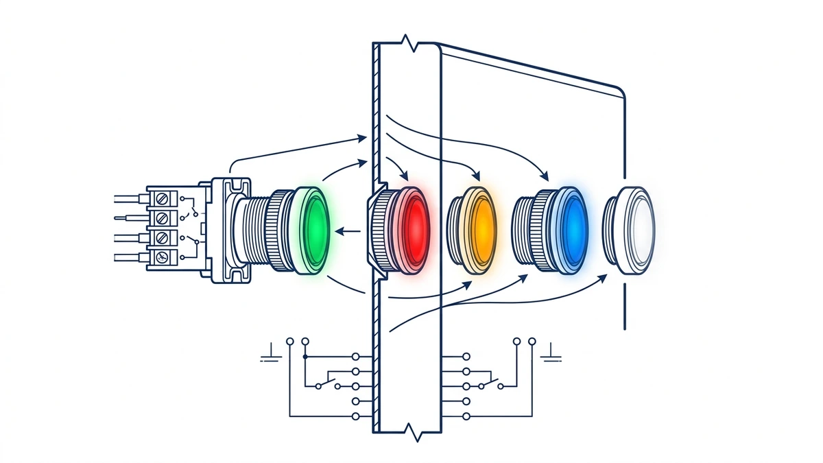
Indicator lights are also called pilot lights in many panel drawings and product catalogs. A typical unit has a front lens or bezel, a lamp or LED module, rear terminals, and a mounting body that fits into a defined panel cutout. Common control-panel voltages include 12 V DC, 24 V DC, 110-120 V AC, and 220-240 V AC, but the exact rating must match the selected device datasheet.
Panel-mounted indicator light structure showing mounting and signal output.
For Shieldhz buyers, indicator lights usually sit in the same operator-interface area as push buttons, selector switches, emergency stop devices, and panel legends. The important point is that the light is not just decorative. It is part of the control logic and should be selected with the same care as the command device beside it.
What Do Indicator Light Colors Mean on a Control Panel?
Indicator light colors communicate machine status, but color alone is not enough. The final meaning should be confirmed by the panel legend, schematic, and machine documentation. IEC 60073 gives coding principles for indicators and actuators, and it is a useful reference when a panel builder wants a consistent signal language.
Common Color Meanings
Color
Common meaning
Typical panel use
Design caution
Red
Fault, stop, trip, danger, energized hazard
Overload, alarm, emergency-related status
Do not use casually for normal operation
Yellow or amber
Warning, abnormal state, attention required
High temperature, standby warning, maintenance alert
Show the required response in the legend
Green
Normal, ready, run, safe condition
Motor running, machine ready, process healthy
Verify whether “green” means ready or running
Blue
Mandatory operator action or special function
Reset required, remote mode, manual intervention
Use only when the action is clear
White or clear
General indication, power available, auxiliary status
Control power present, neutral status, local information
Add a legend if the signal is not obvious
The official IEC publication page for IEC 60073 describes the standard as covering coding principles for indicators and actuators. In practice, that means a panel should use colors in a way that helps rapid recognition, not in a way that creates local surprises.
Why Color Alone Is Not Enough
Panel logic can override the default color expectation. A red light might indicate a trip, a live incoming feeder, or an emergency stop chain fault depending on how the circuit is wired. A green light might mean “motor running” on one panel and “ready to start” on another. That is why good panel design uses color plus text legends, circuit symbols, and wiring references.
Use short engraved legends such as “RUN”, “TRIP”, “POWER”, or “CONTROL PWR”.
Avoid assigning two different meanings to the same color inside one enclosure.
If a signal is safety-related, do not rely on color alone. Pair the light with a label, alarm, HMI message, or relay signal.
Confirm whether local operators read colors by company convention, machine standard, or the original OEM schematic.
How Does Voltage Affect an Indicator Light?
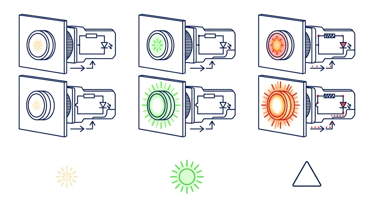
Indicator light voltage determines whether the lamp illuminates correctly, how bright it appears, and how long it lasts. A 24 V DC indicator light should not be connected to a 230 V AC control circuit. A 230 V AC light may not operate correctly on 24 V DC. Even when the lens color is correct, the wrong voltage can create dim output, early failure, overheating, or no signal at all.
Voltage selection affects brightness, service life, and signal reliability.
Common Indicator Light Voltages
Common ratings include:
12 V DC for vehicle, battery, and compact equipment panels
24 V DC for PLC cabinets, sensor circuits, and many machine control panels
48 V DC for some telecom, battery, and special control systems
110-120 V AC for auxiliary control circuits in some regional panel designs
220-240 V AC for mains-derived indication circuits
The selected voltage should match the source feeding the lamp, not the load controlled by the machine. A motor may run on 400 V AC, while the indicator circuit may use 24 V DC. A PV or isolation panel may carry high load voltage, while the local signal lamp still uses a separate auxiliary control voltage.
AC Versus DC
AC and DC indicator lights are not always interchangeable. Some AC versions include rectification or different current-limiting components. Some DC versions are polarity-sensitive. LED modules may include an internal resistor, driver circuit, or rectifier depending on the model and voltage range. The datasheet should state whether the device is AC, DC, or AC/DC compatible.
IEC 60947-5-1 is the usual low-voltage control-circuit device reference for pilot devices and related switching elements. It does not replace the product datasheet, but it gives the standards context for why ratings, insulation, terminals, and operating duty matter.
What Happens When Voltage Is Wrong?
If the applied voltage is too low, the lamp may stay dark or appear too dim to be useful. If the applied voltage is too high, an LED module can fail quickly, and a filament or neon design can overheat or burn out. In a production panel, a failed indicator light is not a small detail because it can mislead operators during startup, alarm response, or maintenance.
How Do Control Panel Indicator Lights Work in a Circuit?
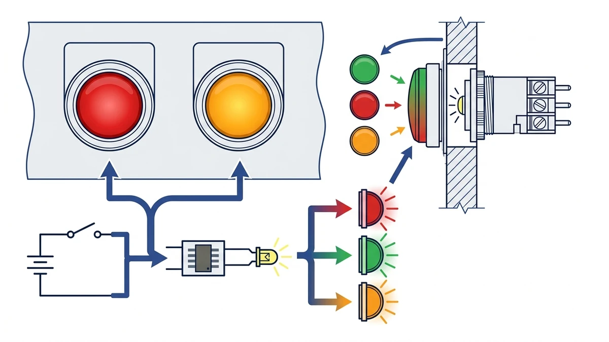
Control panel indicator lights work by converting the presence of control voltage into a visible status signal. The lamp may be connected directly across a supply or controlled through a relay contact, contactor auxiliary contact, push button, PLC output, or selector switch. The circuit condition decides when the light turns on.
Basic circuit logic shows how indicator lights display machine status.
Basic Power-On Circuit
The simplest circuit places an indicator light between line and neutral, or between positive and negative in a DC circuit. When the rated voltage is present, current flows through the lamp module and the lens illuminates. This is often used for “power on” or “control power available” signals.
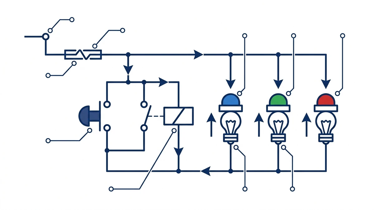
Run, Stop, Alarm, and Fault Signals
In machine panels, the indicator is usually tied to a meaningful circuit condition:
A green run light may turn on when a contactor auxiliary contact closes.
A red fault light may turn on when an overload relay trips.
A yellow warning light may turn on when a sensor detects an abnormal process condition.
A white power light may turn on when the control transformer output is available.
This is why the schematic matters. The same red lens can represent different logic depending on whether it is wired to an overload contact, a safety relay output, or a live feeder indication circuit.
PLC-Controlled Versus Hardwired Signals
In hardwired panels, relay contacts and auxiliary contacts directly energize the lamps. In PLC panels, a controller output may drive the indicator light or an interposing relay. PLC control gives more flexibility, but the output rating and lamp current still have to match. For broader device context across switching, isolation, signaling, and connection hardware, see the Shieldhz product range.
What Types of Indicator Lights Are Used in Panels and Equipment?
Indicator lights are selected by light source, mounting format, function, visibility, and environmental protection. The common modern choice is an LED indicator light, but older panels may still use neon or incandescent lamps.
By Light Source
LED indicator lights are common because they usually draw less current, generate less heat, and last longer than incandescent lamps. They also support multiple colors and voltage options in compact panel hardware. Neon indicators are still found in some AC power indication circuits. Incandescent indicators are mostly seen in older equipment or replacement work.
By Mounting Style
Panel indicator lights are often selected by cutout size. Common sizes include 16 mm, 22 mm, and 30 mm, depending on the panel standard and device series. The front bezel, rear terminal depth, locknut, and gasket all matter because enclosure doors have limited space.
By Function
Common functions include:
Power-on indication
Run or ready status
Alarm or fault indication
Phase, supply, or auxiliary status
Remote mode or manual mode indication
Illuminated push button feedback
An illuminated push button is not the same thing as a standalone indicator light. An illuminated push button combines a command actuator and a light source in one device. A standalone indicator light normally gives status only and does not provide a switching command.
By Environment
Indoor panels may only need standard front protection. Outdoor, dusty, oily, or washdown panels need more careful protection checks. IEC 60529 defines IP ratings, but the product datasheet should state the actual front-face or full-device rating. The gasket, locknut, panel thickness, and installation torque can affect real enclosure performance.
How Do You Choose the Right Indicator Light for a Control Panel?
To choose the right indicator light, match the device to the electrical rating, lens color, mounting size, environment, and operator meaning. Most selection errors happen when the color is chosen first and voltage, cutout, or wiring logic is checked too late.
Selection criteria for matching indicator lights to panel requirements.
1. Match the Electrical Rating
Start with the control circuit voltage and current type. Confirm AC or DC operation, polarity requirements, frequency for AC circuits, and whether the device has an internal resistor, rectifier, or LED driver. Do not assume a similar-looking lens means the same electrical rating.
2. Choose the Color by Signal Priority
Use red for faults, trips, hazardous states, or stop-related signals. Use yellow or amber for warnings. Use green for normal operation, run, or ready status when that meaning is documented. Use blue for required action or special status. Use white for general indication. If the machine already has a color convention, follow the schematic and legend.
3. Confirm Mechanical Fit
Check the panel hole diameter, bezel size, rear clearance, locknut style, and terminal type. Retrofitting a 16 mm device into a 22 mm cutout creates extra work. Installing a deep lamp body behind a shallow enclosure door can also interfere with wiring ducts, terminal blocks, or other devices.
4. Verify the Installation Environment
Check dust, moisture, oil mist, UV exposure, vibration, and cleaning method. For dusty or wet panels, the required ingress rating may be IP65 or higher at the panel front. In a washdown or outdoor enclosure, the indicator light should be considered together with gaskets, door thickness, cable entry, and other front-mounted devices.
5. Check Maintenance and Procurement Details
For repeat panel builds, ask whether the supplier can keep the same lens colors, voltage variants, terminals, and dimensions across batches. Document the model code, voltage, color, and cutout size in the BOM so a future replacement does not rely on visual guessing.
Why Choose a Reliable Indicator Light Supplier for Panel Projects
A reliable indicator light supplier helps panel builders reduce wiring review time, replacement uncertainty, and procurement risk. The device is small, but it sits in front of operators every day. If the color, brightness, voltage, or panel fit is wrong, the panel can become harder to operate and maintain.
For Shieldhz, the indicator light article belongs in the same practical selection path as push buttons, selector switches, and other operator-panel components. Buyers should confirm voltage options, lens colors, cutout size, IP rating, terminal format, certification documents, and sample availability before locking the panel design.
Supplier Evaluation Checklist
Use this checklist when comparing indicator light suppliers:
Confirm rated voltage options such as 12 V, 24 V, 110 V, and 230 V.
Check whether AC, DC, or AC/DC versions are available.
Verify common mounting sizes such as 16 mm and 22 mm.
Review front-face protection claims for dusty or wet panels.
Ask for datasheets, drawings, terminal details, and model code rules.
Confirm lens color consistency across repeat orders.
Check compatibility with nearby push buttons and selector switches.
Request samples for visibility, wiring, and fit checks before batch ordering.
For buyers managing complete operator panels, the fastest next step is to send the control voltage, color list, cutout size, enclosure environment, and expected annual quantity through the Shieldhz technical inquiry route. That gives the supplier enough information to review the indicator light route before a panel build or repeat purchase.
If the purchasing package also needs drawings, certificates, or reference material, use the Shieldhz technical resource library before final BOM approval.
Frequently Asked Questions
What is the main purpose of an indicator light in a control panel?
An indicator light gives immediate visual feedback about power, running status, warnings, or faults. It helps operators and maintenance teams understand what the panel or machine is doing without opening the enclosure or reading the full schematic.
Is an indicator light the same as a pilot light?
In many industrial panel contexts, yes. “Pilot light” is a common term for a panel indicator light used to show circuit or machine status. The exact product name depends on the supplier, market, and panel drawing convention.
What voltage should an indicator light use?
It should match the rated voltage and current type of the control circuit, such as 24 V DC or 230 V AC. The load voltage of the machine is not enough to choose the lamp. Always confirm the control voltage from the schematic or datasheet.
What does a red indicator light usually mean?
Red usually signals a fault, stop condition, trip, emergency-related status, or hazardous energized state. The final meaning still depends on the panel legend and wiring logic.
Are AC and DC indicator lights interchangeable?
Not always. Some models are built only for AC or only for DC. DC types may require correct polarity, while AC types may use different internal components. Use the voltage and current type printed on the device or datasheet.
Why are LED indicator lights common in modern panels?
LED indicator lights typically use less power, run cooler, last longer, and provide stable brightness compared with older incandescent lamps. They also support compact multi-color panel designs.
How do I know what mounting size to order?
Check the panel cutout diameter, bezel dimensions, rear clearance, and panel thickness. Common sizes include 16 mm and 22 mm, but replacement work should always be measured before ordering.
Shi, Muxi
Shi, Muxi writes Shieldhz technical articles for industrial control and electrical component buyers, covering rotary cam switches, isolator switches, PV DC disconnects, push buttons, indicator lights, waterproof enclosures, and terminal blocks. The articles are based on Zhejiang Shihe Electric Co., Ltd.'s manufacturing and export experience, with practical emphasis on model selection, datasheets, drawings, certifications, IP ratings, and inquiry details buyers should confirm before ordering.