A DC isolator switch in a solar PV system is installed at two defined positions: between the solar array and the inverter input (the array-side or string-side isolator), and at the inverter DC terminals as a dedicated service disconnect. Both positions create a load-break isolation point that allows maintenance teams to de-energize each circuit segment independently. Correct placement is governed by system voltage, short-circuit current, enclosure zone, and the requirements of IEC 60364-7-712 and related regional wiring codes. Getting the position wrong — upstream vs. downstream of the inverter, or indoor vs. outdoor enclosure — creates live cable hazards, arc faults, and failed grid-connection inspections. This article explains each position, the variables that shift it, and how to verify the correct switch model before procurement.
The Two Mandatory DC Isolator Positions in a PV System
In many grid-connected solar PV systems, DC isolation is planned around two practical positions that must be checked against the adopted installation standard and inverter manual.
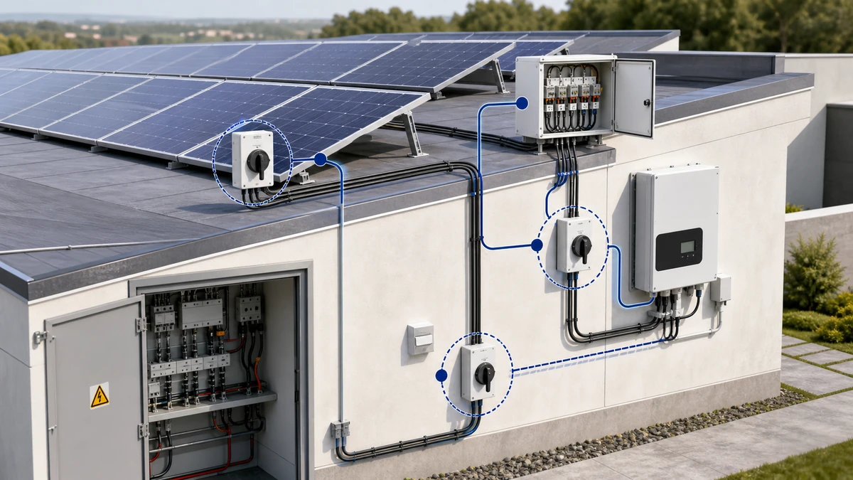
Position 1 — Array-Side DC Isolator. This switch is installed between the string combiner output and the inverter DC input terminals. Its job is to de-energize the high-voltage DC cable run from the array so that inverter servicing, cable fault rectification, or commissioning testing can proceed without live conductors between the panels and the inverter room. The array-side isolator must be rated for the full array open-circuit voltage (Voc) under worst-case cold-temperature conditions, which can exceed the STC nameplate value by a meaningful margin on a clear winter morning. It must also carry the aggregated short-circuit current of all parallel strings feeding the combiner.
Position 2 — Inverter-Side DC Isolator. A second DC isolator is installed at or within close reach of the inverter DC input terminals. This isolator allows service personnel to isolate the inverter DC bus without having to de-energize the entire array or work back to a combiner that may be on a roof or in a remote enclosure. Many regional standards and inverter manuals treat array-side and inverter-side isolation as separate safety functions rather than interchangeable locations.
Where both positions are correctly placed, the full DC system can be de-energized in two controlled switching operations, each verifiable with a voltage meter before work begins.
Figure 1. Core concept behind where to install DC isolator switch selection.
How PV System Architecture Determines Isolator Placement
DC isolator switch placement follows the signal path from array strings through to the inverter AC output. Understanding the node-by-node electrical conditions at each segment is the starting point for any placement decision.
The Core Circuit Path
In a standard string PV system, the DC circuit runs through four primary nodes:
String Array — String Combiner — Array-Side DC Isolator (Position 1) — Inverter DC Input — Inverter-Side DC Isolator (Position 2) — Inverter — AC Distribution
Each transition point carries different voltage and current conditions. PV string open-circuit voltage in typical residential systems commonly ranges from 600 V DC to 1,000 V DC. Maximum power point current per string typically falls between 8 A and 12 A depending on module selection, but the combiner output current equals the sum of all parallel string currents, which is the figure that governs the Position 1 isolator rating.
Why Position 1 Demands a Purpose-Built DC Switch
The array-side isolator at Position 1 must interrupt high-voltage DC current under load. This is a fundamentally different arc-quenching condition compared to AC switching. A DC arc has no natural zero-crossing point: it sustains continuously unless the switch incorporates DC-rated contact geometry, adequate contact separation distance, and a magnetic arc-blowout chamber sized for the operating voltage and current. An AC-rated general-purpose isolator installed at Position 1 cannot reliably extinguish that arc and is a documented cause of switch burnout and enclosure fires in the PV industry.
The GF40 PV DC isolator switch is designed with DC-specific contact geometry and arc-blowout chambers for string-circuit service. Selection must still be confirmed against the project’s actual voltage, current, and pole-count parameters from the array datasheet.
Position 2 in Relation to the Inverter Enclosure
The inverter-side DC isolator at Position 2 is typically a door-mount or DIN-rail switch installed within the inverter enclosure or within a panel-mount enclosure immediately adjacent to it. Inverter manufacturers generally specify a maximum distance from the inverter DC terminals — that manufacturer requirement takes precedence over general installation guidance where the two differ. Where the inverter includes an internal DC disconnect, the installer should confirm whether that internal switch satisfies the regional standard’s requirement for an externally accessible, lockable isolation point.
Field Conditions That Shift the Isolator Mounting Position
Standard layouts assume a short, direct cable run from a rooftop combiner to a wall-mounted inverter. Real sites frequently diverge from that assumption, and each divergence has a defined placement consequence.
Eight Site Conditions and Their Placement Impact
Condition 1 — String voltage exceeds 600 V DC.
Relocate the array-side isolator to within 1 m of the string combiner rather than the inverter, reducing the live cable run length. Confirm the selected switch is rated for the full calculated cold-temperature Voc of the array. The GF51 PV DC isolator switch is designed for higher-voltage PV string service; verify ratings against the project datasheet.
Condition 2 — Inverter is wall-mounted indoors.
Place an additional DC isolator at the building wall penetration point so the indoor cable run from penetration to inverter can be de-energized independently without returning to the roof.
Condition 3 — Rooftop array on a flat commercial roof.
Mount the array-side isolator within 600 mm of the array boundary edge, accessible without crossing energized panel surfaces. Emergency responder access is the governing requirement in most commercial building codes.
Condition 4 — DC cable run from array to inverter exceeds 10 m.
Consider an intermediate isolation point at the cable route entry point into the building to limit exposed live cable length inside the structure.
Condition 5 — Outdoor enclosure exposed to driving rain or coastal salt spray.
Select an enclosure rated to a minimum of IP65 per IEC 60529 for standard outdoor service. For marine or coastal environments with persistent salt-laden humidity, IP66 or IP67 is the appropriate minimum. Understanding the practical differences between these ratings is covered in IEC 60529 ingress protection guidance.
Condition 6 — Multiple strings feeding a combiner.
Place a dedicated string-level isolator at each combiner input before the common DC bus in addition to the combiner output isolator. A single main isolator at the combiner output cannot safely de-energize individual strings for string-level fault diagnosis.
Condition 7 — Array installed on a carport or ground-mount structure.
Position the array-side isolator at the structure perimeter at a mounting height accessible to emergency responders — typically between 0.6 m and 1.8 m above finished grade, subject to local fire authority requirements.
Condition 8 — Bifacial or east-west split arrays with parallel sub-arrays.
Each independent sub-array requires its own isolator. A single inverter-side switch cannot de-energize parallel voltage sources independently, and the combined Isc of the parallel sub-arrays must be confirmed against the combiner output isolator rating.
Where two or more of these conditions apply simultaneously, the most restrictive placement rule takes precedence. Document which condition drives the final mounting position and include that record in the commissioning pack.
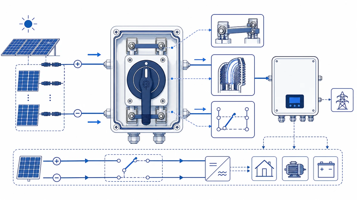
Figure 2. Selection checks should connect DC voltage, string current, pole count, enclosure, cable entry, and documentation.
Regulatory Standards That Govern DC Isolator Placement
Field conditions define where an isolator can physically be installed. Regulatory standards define where it must be installed. Both sets of requirements must align before a system passes grid-connection inspection.
Regional Standard Reference Summary
Standard
Key Placement Requirement
Primary Region
AS/NZS 5033:2021
Defines array-side isolation, accessibility, enclosure, and maximum-voltage verification rules; confirm the adopted edition and local amendments
Australia and New Zealand
IEC 62548:2016
Means of isolation required on the DC side, accessible without tools, positioned to de-energize the full source circuit before inverter servicing
International, EU, MENA, Southeast Asia
BS 7671:2018+A2:2022 Reg. 712.537.2
Defines PV DC isolation and accessibility requirements; confirm placement and rating calculations against the project design
United Kingdom
NEC 2023 Art. 690.15
Defines PV output-circuit disconnecting means; rapid-shutdown rules may also apply depending on array and building configuration
United States
IEC 60947-3:2020+AMD1:2025
Applies to switches, disconnectors, switch-disconnectors, and fuse-combination units for distribution and motor circuits, rated voltage up to 1000 V AC or 1500 V DC; isolating devices must achieve rated insulation voltage Ui at or above operating voltage and open all poles simultaneously
International product certification
The current edition of IEC 60947-3 is available directly from the IEC Webstore. Buyers specifying products for export projects should confirm which edition and amendment is referenced in the applicable national adoption or procurement specification.
For a detailed explanation of how IEC 60947-3 governs switch-disconnector design and testing, see IEC 60947-3 scope guidance.
Enclosure Rating Requirements Under Regional Standards
Most regional standards mandate a minimum of IP65 per IEC 60529 for rooftop and exposed outdoor mounting positions. Submersible or ground-mount flood-risk positions may require IP67. Confirm the specific IP clause in the adopted standard for the project jurisdiction before finalizing the enclosure specification. IP rating is a verifiable, certifiable parameter — not a general-purpose claim — and should be checked against the product datasheet and certificate for the exact model being installed.
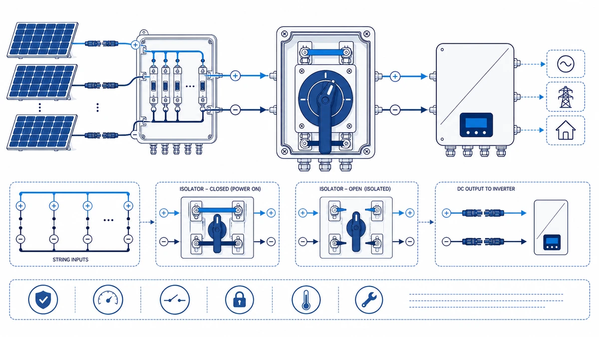
Figure 3. Application wiring context should be verified against the manufacturer contact chart before energizing.
Selection Parameters: Matching the Switch to the Installation Position
Choosing the correct DC isolator switch requires aligning four interdependent parameters to the actual conditions at each installation point.
Parameter 1 — DC System Voltage
Calculate array Voc at the lowest recorded ambient temperature for the site, not at STC. Cold-temperature Voc can exceed the nameplate STC value by 10 percent to 15 percent on a clear winter morning at altitude. The switch rated insulation voltage (Ui) must equal or exceed this calculated maximum. Specifying to the STC Voc value alone is a documented undersizing error.
Parameter 2 — Short-Circuit Current
On multi-string combiners, the prospective short-circuit current at the combiner output equals the sum of each string’s Isc multiplied by the applicable safety factor defined in the installation standard — commonly 1.25 in IEC-based jurisdictions. The isolator current rating must cover this aggregated value, not the per-string current.
Parameter 3 — Ingress Protection Zone
Map each isolator mounting position to its exposure zone: rooftop outdoor (typically IP65 minimum), direct weather exposure or marine (IP66 or IP67), or indoor inverter room (IP40 to IP54 depending on local requirements). The zone classification drives enclosure selection independently of the switch current and voltage ratings.
Parameter 4 — Pole Count and Earthing Arrangement
Ungrounded (floating) DC string systems require a 2-pole isolator that simultaneously opens both the positive and negative conductors. A single-pole isolator on an ungrounded system leaves one conductor live after switching, which does not constitute true isolation. Some jurisdictions and system configurations require 4-pole switching for main DC combiner disconnects — verify against the applicable wiring code and the inverter manufacturer’s installation manual.
Model Orientation by Application Zone
For string combiner rooftop positions, GF40 is a commonly specified option when voltage, current, and enclosure requirements match its datasheet. For higher-voltage commercial string service, GF51 covers that duty where the project ratings fit. The GF41 solar DC switch is suited to mid-range residential and light commercial string applications. All final model selections must be cross-referenced against the relevant product datasheet, wiring diagram, and certificate documentation for the rated voltage, current, pole count, and IP class applicable to the project.
How Shieldhz Confirms DC Isolator Specifications for Solar PV Projects
Shieldhz is the export brand of Zhejiang Shihe Electric Co., Ltd., founded in 2014 and headquartered in Yueqing, Wenzhou, Zhejiang — a recognized manufacturing base for low-voltage electrical components. The facility covers over 5,000 square meters, employs more than 100 staff, and operates 40-plus production machines. The product certification base includes CE, TUV, ISO 9001, RoHS, UKCA, CCC, CB, and UL where applicable by product family.
Specifying a DC isolator for a PV project involves more than matching a voltage number to a nameplate. The following is how Shieldhz works through a structured specification review for solar installation projects.
Step 1 — Array Voltage and String Current Confirmation
The first check aligns the switch voltage rating with the array’s calculated cold-temperature Voc, not the inverter nominal input voltage. For string systems commonly deployed in residential and commercial projects, this value falls between 600 V DC and 1,000 V DC, though commercial high-voltage strings at 1,500 V DC require a separately rated product line. Shieldhz confirms pole count and current rating at the same step, using the buyer’s array layout diagram or string configuration table.
Step 2 — IP Zone and Enclosure Class Verification
The mounting position — rooftop combiner, ground-mount DC bus enclosure, or inverter room — determines the required IP class under IEC 60529. Shieldhz maps the buyer’s stated installation zone to the enclosure rating on the product datasheet and flags any mismatch before order confirmation.
Step 3 — Utilization Category and Contact Program Check
DC isolator switches carry a utilization category that governs their breaking and making capacity under DC load conditions. Shieldhz reviews the utilization category on the candidate model against the system’s calculated fault current and confirms the contact program against the wiring diagram for the specific pole and terminal configuration required.
Step 4 — Certificate and Documentation Package
For export projects, Shieldhz reviews the required certification package — CE Declaration of Conformity, TUV test report, or market-specific documentation — against the buyer’s regional installation standard before production confirmation. Wiring diagrams, dimensional drawings, and datasheets are available for buyer review at the quotation stage. Buyers can submit string layout diagrams, inverter datasheets, IP zone classification, and regional standard references through the Shieldhz inquiry channel to receive a verified model recommendation before placing an order. The complete DC isolator switch product family can be reviewed as a starting point for model shortlisting.
Common Installation Mistakes and How to Avoid Them
Mistake 1 — Installing an AC-Rated Isolator on the DC String Circuit
AC contact geometry cannot extinguish a sustained DC arc. The arc has no natural zero-crossing and will burn continuously, causing contact erosion, switch burnout, or enclosure fire. Corrective action: specify a switch with a DC utilization category and a voltage rating confirmed against the array’s cold-temperature Voc. Verify the DC breaking capacity on the product datasheet, not only the AC rating on the nameplate.
Mistake 2 — Mounting the Rooftop Isolator in an Unrated Enclosure
Using an IP20 or IP40 indoor switch housing in an outdoor or semi-exposed rooftop position allows moisture ingress that degrades insulation resistance, promotes tracking, and causes ground faults. Corrective action: specify a weatherproof enclosure at the IP class appropriate to the installation zone — IP65 as a standard minimum, IP66 or IP67 for marine or high-rainfall environments.
Mistake 3 — Placing the Array Isolator Downstream of the Inverter DC Input
This is a single-line diagram misreading error that leaves string conductors live during inverter servicing. The array-side DC isolator must be positioned between the string combiner output and the inverter DC input terminals — upstream of the inverter, not on the inverter output side.
Mistake 4 — Undersizing the Switch for Multi-String Combiner Output Current
Rating the switch for single-string Isc without accounting for parallel string aggregation causes continuous overcurrent that accelerates contact erosion. Corrective action: calculate total Isc at the combiner output — 1.25 multiplied by the per-string Isc multiplied by the number of parallel strings — and select a switch rated at or above that figure. Confirm the exact safety factor specified in the applicable installation standard.
Mistake 5 — Omitting the Dedicated Inverter-Side DC Disconnect
Assuming the array-side isolator serves both functions leaves service personnel unable to isolate the inverter DC bus without de-energizing the entire array. Corrective action: install a separate DC isolator at or immediately adjacent to the inverter DC terminals as a distinct, lockable disconnect point.
Mistake 6 — Incorrect Pole Count on an Ungrounded System
A single-pole isolator on an ungrounded DC string leaves one conductor live after switching and does not achieve true isolation. Corrective action: use a 2-pole isolator that simultaneously opens both the positive and negative conductors, fully de-energizing the circuit regardless of earthing configuration.
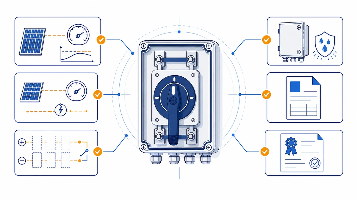
Figure 4. A complete inquiry should include rating, contact sequence, mounting, enclosure, and document requirements.
Frequently Asked Questions
Can I use a standard AC isolator switch on a solar PV DC string circuit?
No. AC-rated isolators are not suitable for PV string circuits. Their contact geometry and arc-quenching chambers are designed for AC load conditions where the current naturally crosses zero twice per cycle, extinguishing the arc. A DC arc has no zero-crossing and will sustain continuously until the contacts fail or the switch enclosure burns. Only switches carrying a DC utilization category and a voltage rating confirmed against the array’s open-circuit voltage should be used at any DC position in a PV system.
How close to the solar panels does the array-side DC isolator need to be?
Placement distance requirements vary by standard and local amendment. Some markets define a fixed distance from the array junction point, while IEC-based guidance often uses the principle of placing isolation as close to the source as practicable. BS 7671 and NEC projects each carry their own distance, accessibility, and rapid-shutdown requirements. Always confirm the exact distance rule in the standard adopted by the project jurisdiction, and document the as-installed position in the commissioning record.
What IP rating is required for a DC isolator mounted on a rooftop?
Outdoor and rooftop positions commonly use IP65 or higher under IEC 60529, depending on exposure. Sites subject to coastal salt fog, heavy rainfall, or periodic pressure washing may need IP66 or IP67 rated enclosures. Confirm whether the local authority’s adopted standard or project specification sets a rating above IP65 before finalizing the enclosure specification.
Do I need a separate DC isolator at the inverter if one is already installed at the combiner?
Often yes, because the two positions serve distinct safety functions. The array-side isolator de-energizes the string cable run. The inverter-side isolator allows service personnel to work on the inverter without returning to the array, disturbing the combiner, or de-energizing the entire system unnecessarily. Confirm the final requirement against the adopted installation standard and inverter manual.
How is the correct current rating calculated for a DC isolator on a multi-string combiner?
The standard approach is to multiply the module Isc rating by the applicable safety factor — commonly 1.25 in IEC-based markets — and then multiply by the number of parallel strings feeding the combiner. The isolator must be rated at or above the result. Confirm the exact safety factor specified in the applicable national or IEC standard, as some markets use a higher multiplier. Use the module datasheet Isc value at STC as the input figure, not the inverter maximum input current.
Why does a 1,500 V DC rated isolator matter for commercial solar arrays?
Commercial and utility-scale PV systems frequently operate string voltages above 1,000 V DC to reduce cable current, minimize cable cross-section costs, and reduce inverter input current per string. An isolator rated only to 1,000 V DC cannot safely withstand or interrupt those higher voltages. Rated insulation voltage (Ui) must equal or exceed the maximum operating voltage at every point in the circuit. Verify the rated voltage on the product datasheet and certificate, not only the product name or catalog description.
What happens if the pole count of the isolator does not match the system earthing arrangement?
On ungrounded (floating) DC string systems, a single-pole isolator leaves one conductor energized after the switch opens. That conductor remains at a voltage relative to earth, which does not constitute true isolation and creates a latent shock and arc-fault hazard during subsequent work. The correct solution for ungrounded systems is a 2-pole isolator that simultaneously opens both the positive and negative conductors, fully de-energizing the circuit segment regardless of the system earthing configuration.
Shi, Muxi
Shi, Muxi writes Shieldhz technical articles for industrial control and electrical component buyers, covering rotary cam switches, isolator switches, PV DC disconnects, push buttons, indicator lights, waterproof enclosures, and terminal blocks. The articles are based on Zhejiang Shihe Electric Co., Ltd.'s manufacturing and export experience, with practical emphasis on model selection, datasheets, drawings, certifications, IP ratings, and inquiry details buyers should confirm before ordering.