DC isolator switch wiring between a string combiner and inverter requires a dedicated disconnect point that interrupts the full DC bus before the inverter input terminals. In a typical rooftop or ground-mount PV system, the string combiner aggregates multiple string circuits, each carrying open-circuit voltage up to 1,000 V DC or 1,500 V DC, into a single fused DC output rail that feeds the inverter. The isolator must be correctly rated for DC voltage, continuous current, utilization category, and enclosure protection class before a single conductor is terminated. Selecting and wiring the wrong switch creates latent fault risk that thermal imaging and commissioning checklists may not detect until a fault event occurs.
Electrical Parameters That Define the Wiring Route
The isolator switch must be selected and wired around three core ratings: maximum system voltage, maximum continuous current at the combiner output, and short-circuit current rating no lower than the prospective fault current at that output.
Maximum system voltage is commonly 1,000 V DC for residential and commercial installations per IEC 60364-7-712, or 1,500 V DC for utility-scale arrays. For a four-string combiner where each string produces 10 A, the isolator must handle at least 40 A DC at system voltage, with a safety margin confirmed from the selected switch datasheet’s rated making and breaking capacity under DC-21B, DC-22B, or a PV-specific utilization category per the switch-disconnector standard.
The governing standard for this application is official IEC switch-disconnector publication, which applies to switches, disconnectors, switch-disconnectors, and fuse-combination units for distribution and motor circuits, with rated voltage up to 1,000 V AC or 1,500 V DC. PV-specific utilization categories DC-PV1 and DC-PV2 are addressed in Annex P of that standard. For a full orientation to what the standard requires of a device in this circuit position, see the Shieldhz reference on switch-disconnector standard scope.
Rated Parameters Reference Table
Parameter
Typical Field Requirement
Governing Reference
Field Note
Maximum DC voltage
1,000 V DC or 1,500 V DC
the switch-disconnector standard
Must exceed string Voc at lowest recorded ambient temperature, not STC
Rated current
1.25 x Isc per combined string output
IEC 60364-7-712
Derate further for continuous DC load; combiner output stacks multiple strings
Utilization category
DC-PV1 (grounded) or DC-PV2 (ungrounded/floating)
the switch-disconnector standard Annex P
DC-PV2 requires enhanced arc-breaking capacity; confirm inverter topology before specifying
Rated insulation voltage
Greater than or equal to system Voc under all temperature conditions
the switch-disconnector standard
Ui must cover worst-case cold-temperature Voc
Enclosure ingress protection
IP65 minimum outdoor; IP66 or IP67 for exposed or coastal locations
IEC 60529
Combiner-to-inverter runs are frequently partially sheltered but not fully protected
Utilization Category DC-PV1 vs. DC-PV2
Whether the array is solidly grounded (DC-PV1) or floating and ungrounded (DC-PV2) determines the arc-breaking demand placed on the isolator contacts. DC-PV2 applications impose higher clearing energy because fault current has no defined ground return path. A device tested only for DC-PV1 duty may fail to clear a fault on a transformerless inverter system, with contact welding or sustained arcing as the failure mode.
For combiner outputs feeding central or string inverters rated above 600 V DC, purpose-built PV DC isolator switches conforming to the switch-disconnector standard Annex P are the standard field specification. Always verify the isolator’s rated operational voltage against the worst-case Voc calculated at the site’s minimum design temperature, a value that routinely exceeds the STC nameplate figure by 5 to 10 percent in cold climates.
Pull the module manufacturer’s temperature coefficient for Voc and calculate worst-case Voc at the site’s recorded minimum temperature before ordering any isolator. For mixed-inverter sites where some units are transformer-isolated and others are transformerless, confirm the grounding topology of each inverter individually. The same combiner row may require different utilization categories at different inverter connections. Request the switch-disconnector standard Annex P test certificates rather than accepting a general voltage rating. A switch marked “1,000 V DC” without Annex P documentation has not been tested for PV arc-breaking duty.
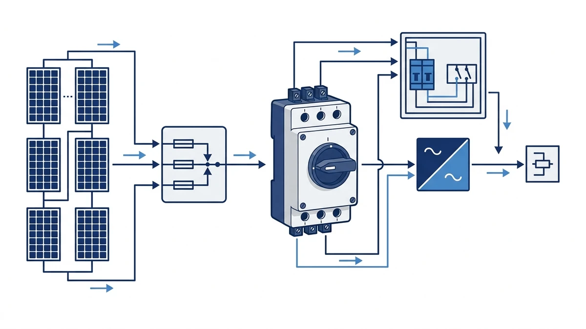
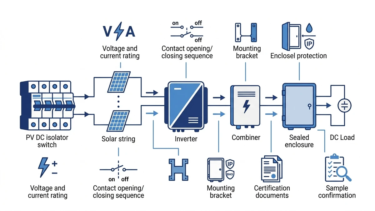
Figure 1. Core concept behind DC isolator switch wiring solar selection.
Physical Wiring Topology in Field Conditions
In field installations, the combiner’s positive and negative bus bars each require a separate switched pole so that both conductors are interrupted simultaneously. This is a two-pole minimum configuration for an ungrounded DC system. Wiring from the combiner output runs through conduit or cable tray to the isolator’s line terminals, then continues to the inverter’s DC input.
Cable sizing follows voltage-drop calculations targeting no more than 1 percent drop across the combiner-to-inverter segment to protect inverter MPPT accuracy. Conductor cross-section selection must also account for conduit fill, ambient temperature correction, and the terminal acceptance range of the selected isolator frame.
For outdoor installations, the isolator enclosure must carry at minimum IP65 per IEC 60529, preventing moisture ingress that accelerates DC arc tracking across unprotected terminals. Understanding the differences between IP65, IP66, and IP67 ratings matters in this circuit position because a combiner-to-inverter run that passes through partially sheltered cable trays may experience water jet exposure during roof maintenance or storm events. The Shieldhz reference on IP rating requirements provides a working comparison of those classes for field selection decisions.
The GF40 PV DC isolator switch is designed for this field position, integrating rated DC breaking capacity within an ingress-protected housing suited to combiner-to-inverter wiring runs. Confirm the datasheet for the specific current frame, pole configuration, and enclosure rating before specifying.
Qualified-Personnel Wiring Documentation Sequence
The procedure below applies to residential and commercial PV systems operating at string voltages up to 1,000 V DC and combined string currents within the isolator’s rated breaking capacity. Adapt it to site-specific wiring rules and the applicable national standard.
Safety boundary: This section is not a DIY wiring instruction. PV DC isolator wiring, commissioning, maintenance, and fault checks should be handled by qualified electrical personnel under the project safety procedure. Before opening an enclosure or checking terminals, follow lockout/tagout, de-energize the relevant circuit where the procedure requires it, and verify absence of voltage with suitable DC-rated test equipment.
Pre-Work Safety Hold Points
Before touching any conductor, confirm the following:
All PV string circuits are shaded or blocked, reducing open-circuit voltage to the lowest achievable level.
The inverter DC input switch is in the OFF position and locked out per site lockout/tagout procedures.
A calibrated DC voltmeter rated for at least the system’s maximum DC voltage is on hand and tested against a known source.
Documentation Sequence for Qualified Installers
Step 1: Verify isolator ratings. Confirm the selected DC isolator switch carries a DC voltage rating greater than or equal to the system’s maximum open-circuit voltage and a current rating greater than or equal to 1.25 times the combined string short-circuit current, in line with IEC 60364-7-712 sizing guidance.
Step 2: Mount the isolator enclosure. Position the unit between the string combiner output terminals and the inverter DC input, accessible for operation and maintenance. Orient the enclosure so conduit entries face downward to prevent water ingress, particularly on rooftop installations where the field IP requirement is confirmed from the location assessment.
Step 3: Run and dress DC cables. Pull positive and negative conductors from the combiner through separate conduit or bundled per local wiring rules. Maintain minimum bend radius to avoid insulation stress at the isolator entry point; check the cable manufacturer’s data for the specific conductor type in use.
Step 4: Terminate combiner-side conductors. Connect the combined positive feed to the isolator’s line-side positive terminal and the combined negative to the line-side negative terminal. Torque cable lug terminations to the value stated on the switch datasheet; do not use a generic reference torque figure. The correct value depends on terminal design, conductor cross-section, and lug type.
Step 5 – Hold Point – Pre-energization check. Using the DC voltmeter, measure across line-side terminals with the isolator in the open position. Confirm polarity is correct and voltage does not exceed the isolator’s rated DC voltage. Do not proceed until the reading is within expected range and polarity is confirmed.
Step 6: Terminate inverter-side conductors. Connect load-side positive and negative conductors to the inverter DC input terminals, observing polarity markings. For installations using the GF51 PV DC isolator, verify the handle position indicator aligns with OFF before making load-side connections.
Step 7: Close isolator and confirm operation. Turn the isolator handle to ON, then verify inverter DC bus voltage appears on the inverter display. Log the measured voltage and current for commissioning records. Compare the measured DC input voltage against the calculated worst-case Voc range for ambient conditions at the time of commissioning.
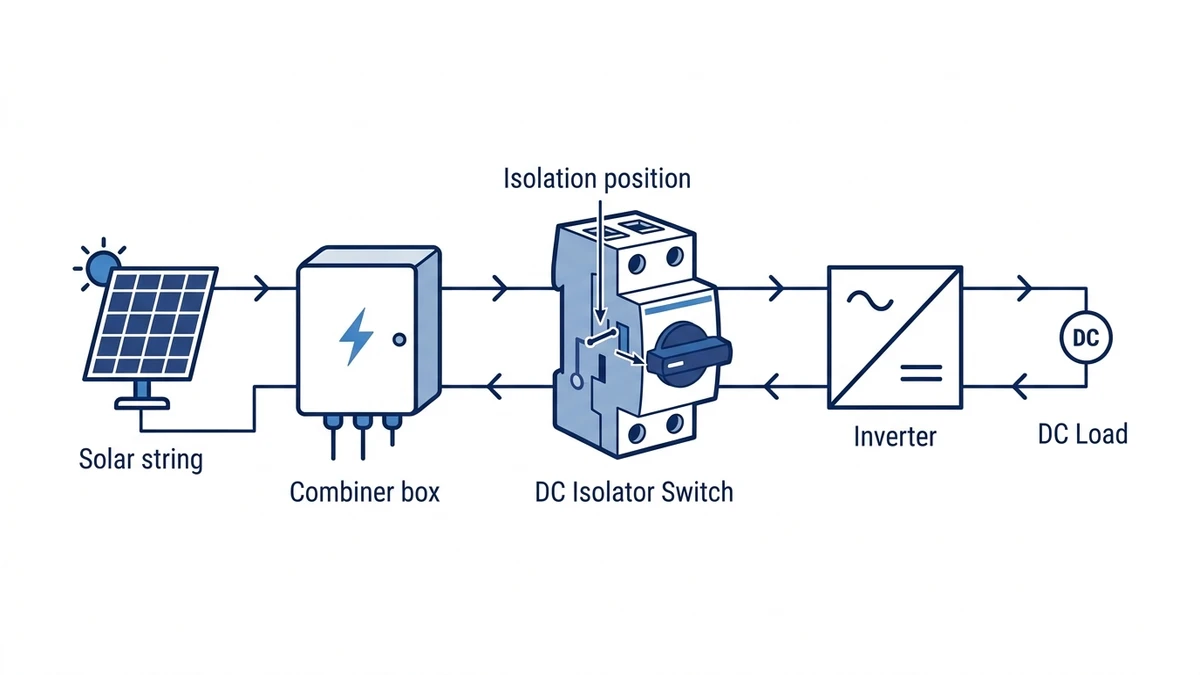
Figure 2. Selection checks should connect DC voltage, string current, pole count, enclosure, cable entry, and documentation.
Field Conditions That Affect DC Isolator Selection and Placement
Enclosure class, mounting location, ambient temperature, and cable routing geometry all influence which isolator configuration remains safe and code-compliant over the installation’s service life.
Enclosure Rating vs. Mounting Location
Mounting Location
Minimum Enclosure Rating
Selection Note
Outdoor, fully exposed
IP65 or IP66
Confirm UV-stabilised housing material
Outdoor, under canopy or awning
IP54 minimum, IP65 preferred
IP65 preferred where maintenance activities may involve water
Indoor, ventilated enclosure
IP20 to IP40
Confirm enclosure ambient temperature against switch rating
Coastal or high-humidity zone
IP66 with UV-stabilised housing
Standard polycarbonate degrades significantly within 3 to 5 years under salt-laden UV exposure
Temperature Derating
Ambient temperature directly affects continuous current capacity. In rooftop installations, surface-mounted isolator enclosures can reach internal air temperatures significantly above ambient on still, sunny days. Most DC isolator frames are rated at a reference ambient of 40 degrees Celsius. For installations where enclosure interior temperatures routinely exceed that reference, apply the manufacturer’s derating curve and select the next current frame upward. Do not assume the nameplate current rating applies at elevated internal enclosure temperatures without reviewing the derating data in the product datasheet.
Unventilated enclosures on dark metal roofs can sustain internal air temperatures well above the switch’s reference ambient in peak summer. Check that any enclosed combiner room or inverter shelter is mechanically ventilated before assuming the standard ambient rating applies.
Cable Routing Conditions
Cable entry angle, conduit fill, and bend radius affect both mechanical stress on terminals and thermal dissipation. Where DC cables enter the isolator from below, which is common in inverter-side mounting, the drip-loop configuration prevents moisture ingress even at moderate IP-rated enclosures. Parallel cable bundles routed in conduit at elevated ambient temperatures require ampacity correction per applicable national wiring rules, which may increase conductor cross-section and consequently the terminal size requirement on the selected isolator frame.
For multi-string combiners feeding a central inverter, reviewing the full PV DC isolator switch range helps identify frames with compatible terminal blocks and enclosure options for the cable sizes in use.
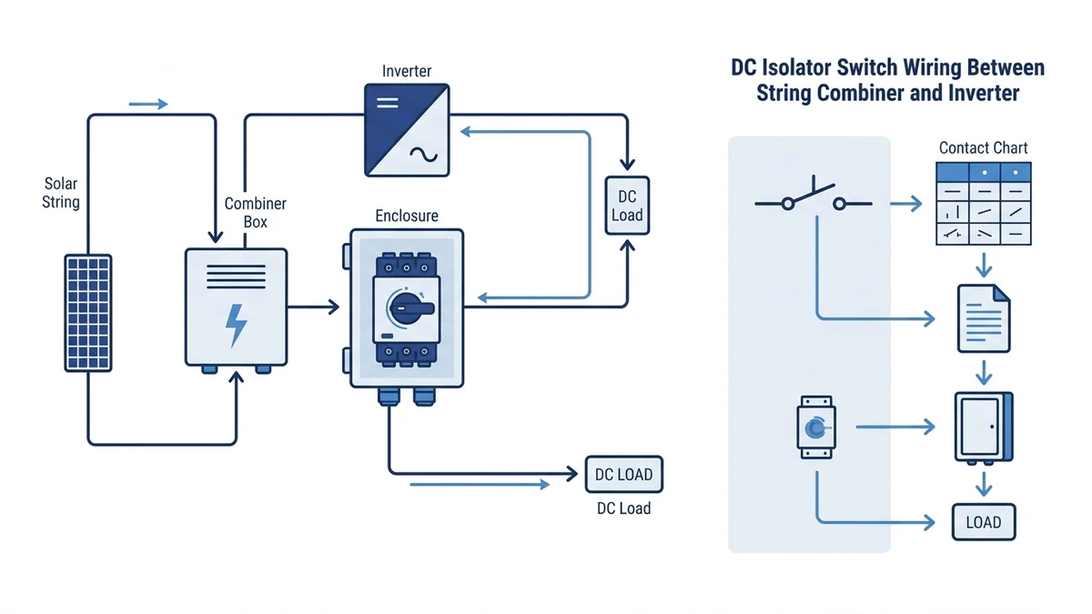
Figure 3. Application wiring context should be verified against the manufacturer contact chart before commissioning.
Common Wiring Faults and How to Identify Them on Site
DC isolator switch wiring faults between the string combiner and inverter are among the most common causes of system underperformance and nuisance shutdowns in PV installations.
Symptom: Inverter Reports Isolation Fault or Will Not Start
Root Cause: Reversed polarity at the DC isolator input terminals. This occurs when positive and negative conductors from the combiner are transposed during termination, producing a negative voltage reference at the inverter DC input stage.
Corrective Action: De-energize the string circuits using the combiner fuses. Use a calibrated DC multimeter to verify polarity at the isolator’s line-side terminals before reconnection. Confirm conductor colour-coding against the site wiring schedule before re-terminating.
Symptom: Below-Expected DC Output Voltage with Normal Irradiance
Root Cause: High-resistance connection at the isolator’s load-side terminals, typically caused by under-torqued cable lugs. Under-torqued terminations allow micro-arcing under load current, which progressively increases contact resistance and produces a measurable voltage drop across the isolator even in the closed position.
Corrective Action: Re-torque all terminals to the manufacturer’s specified value using a calibrated torque screwdriver. Measure contact voltage drop across closed contacts at rated current. Values that significantly exceed the isolator’s datasheet specification for voltage drop warrant terminal replacement or isolator substitution.
Symptom: Intermittent Ground Fault Alarms After Rainfall
Root Cause: Moisture ingress into an insufficiently rated or degraded enclosure. Enclosures with degraded gaskets or unsealed cable entries fall below their rated IP class and allow condensation on live DC terminals, creating a partial leakage path that the inverter’s ground fault detection circuit interprets as an insulation fault.
Corrective Action: Inspect all cable entry glands and enclosure gaskets. Replace any gland showing cracking or compression set. For sites with high seasonal rainfall, upgrading to a higher IP class enclosure variant is preferable to repeated gasket maintenance. Confirm the replacement enclosure’s IP rating covers the specific installation exposure type as defined in IEC 60529.
Symptom: Handle Turns Freely But Circuit Does Not Open
Root Cause: Mechanical disconnection between the actuator shaft and the internal cam or contact mechanism, often caused by over-rotation, impact damage, or mechanical fatigue in high-cycling applications. This fault creates a dangerous latent condition: the operator believes the circuit is isolated while live voltage remains present at the load-side terminals.
Corrective Action: Do not rely on handle position as sole isolation confirmation at any point during live work preparation. Always verify zero voltage at the load-side terminals with a rated DC voltmeter before any downstream work. Replace the isolator immediately. This fault is not field-repairable and the device must be removed from service.
How Shieldhz Confirms Model Route and Wiring Documentation for PV Isolator Applications
Shieldhz is the export brand of Zhejiang Shihe Electric Co., Ltd., founded in 2014 and based in the Yueqing electrical manufacturing cluster in Zhejiang, China. The facility covers more than 5,000 square metres, employs more than 100 staff, and operates more than 40 production machines. The product range is supported by ISO 9001 quality management certification, and individual products carry CE, TUV, RoHS, UL, UKCA, CCC, and CB documentation depending on the target market and product family.
When a buyer submits an inquiry for a DC isolator switch between a string combiner and inverter, Shieldhz works through a structured specification checklist before confirming a model route or issuing a quotation. The goal is to prevent under-specified or misapplied devices from reaching site.
Buyer Inputs Requested at Inquiry Stage
System DC voltage: maximum open-circuit string voltage under cold-temperature conditions, typically 600 V DC, 1,000 V DC, or 1,500 V DC
Combined string current: total Isc at the combiner output, which determines current frame selection
Number of poles required: 2-pole for grounded systems, 4-pole for ungrounded or floating DC bus configurations
Enclosure IP rating: confirmed from the mounting location and exposure type assessment
Applicable installation standard: IEC 60364-7-712, NEC 690, AS/NZS 5033, or equivalent
Required certifications and documentation: TUV, the switch-disconnector standard test report, UL 98B, or market-specific certificate package
Once buyer inputs are confirmed, Shieldhz cross-references submitted parameters against the relevant product series and provides a matched datasheet, wiring diagram, terminal connection table, mounting drawing, and available certificate package. For the GF40 series, this includes the utilization category designation, rated making and breaking capacity data, contact program reference, and enclosure IP certification. Buyers can submit system parameters directly to the Shieldhz engineering team to receive a model-specific recommendation and documentation set before committing to a purchase order.
Maintenance Inspection and Replacement Intervals for DC Isolators in PV Systems
In rooftop and ground-mount PV systems, isolators are exposed to continuous UV radiation, thermal cycling, and moisture ingress. These conditions accelerate contact oxidation, housing embrittlement, and terminal loosening faster than indoor industrial environments at comparable operating hours.
Scheduled Inspection Reference Table
Inspection Item
Suggested Interval
Pass Criterion
Terminal torque check
Every 12 months
Re-torque to datasheet value; investigate if torque loss is significant
Contact voltage drop measurement
Every 12 months
Within datasheet specification; investigate any pole asymmetry
Enclosure seal and IP integrity
Every 6 months
No visible cracking, seal compression loss, or ingress marks
Handle and actuator operation
Every 6 months
Smooth make and break action with positive detent
Cable insulation and gland condition
Every 12 months
No discolouration, cracking, or exposed conductor; glands fully seated
Thermal imaging of live terminals
Annually or after any fault event
No hotspot exceeding datasheet temperature rise limit under rated load
Full switch replacement
Per manufacturer endurance rating or on degradation finding
Replace before rated operation count is reached in high-cycling applications
For isolators in the GF40 series, confirm the published mechanical endurance rating and contact resistance limits from the product datasheet before setting site-specific intervals. High-irradiance or coastal sites with salt-laden air typically warrant six-month full inspections rather than annual cycles.
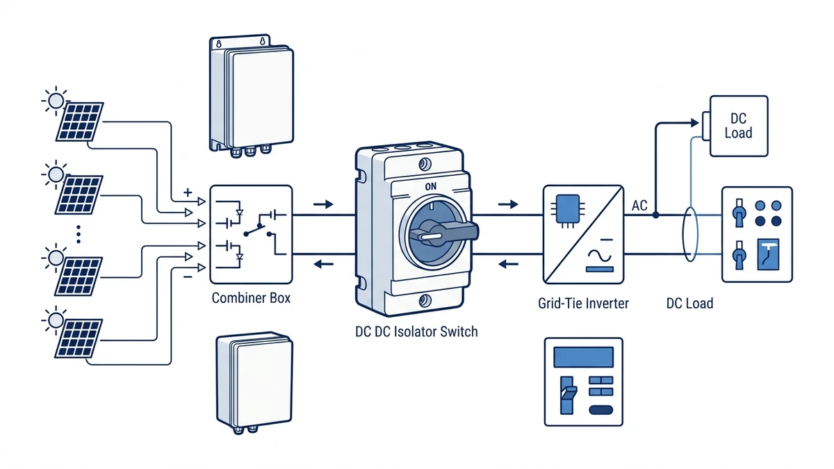
Figure 4. A complete inquiry should include rating, contact sequence, mounting, enclosure, and document requirements.
Frequently Asked Questions
What is the minimum DC voltage rating required for an isolator switch between a string combiner and inverter?
The isolator’s rated operational voltage must exceed the array’s worst-case open-circuit voltage calculated at the site’s lowest recorded ambient temperature, which typically runs 5 to 10 percent above the STC nameplate figure in cold climates. For most commercial string inverter systems, this means specifying a 1,000 V DC rated device as a minimum, even when nominal string voltage sits below that threshold under standard conditions.
Why does utilization category matter when selecting a PV DC isolator?
DC-PV1 and DC-PV2 categories define the arc energy the switch must safely interrupt under grounded and floating bus conditions respectively. A device tested only for DC-PV1 duty may fail to clear a fault on a transformerless inverter system, resulting in contact welding or sustained arcing. The PV DC isolator switch overview explains how utilization categories map to inverter topology and why the distinction is material for procurement documentation.
How many poles does a DC isolator need between a string combiner and inverter?
A two-pole isolator is the minimum requirement for an ungrounded DC system, ensuring both the positive and negative conductors are interrupted simultaneously rather than leaving one conductor live. Systems with a floating or centre-tapped DC bus may require a four-pole configuration. Confirm the inverter topology and local wiring rules before specifying pole count, and verify the selected product is available in the required pole configuration from the datasheet.
What IP rating is required for a DC isolator mounted outdoors near the inverter?
IP65 is the accepted field minimum for outdoor PV wiring runs under IEC 60529. IP66 or IP67 is recommended for fully exposed locations, coastal environments, or sites subject to high-pressure cleaning during roof maintenance. An IP rating printed on the enclosure is only maintained if all cable entry glands are correctly installed, seated, and sealed to the same protection class as the enclosure body.
How often should terminal torque be checked on a DC isolator in a PV system?
Annual re-torquing is the standard interval for most installations, performed using a calibrated torque screwdriver against the value stated in the isolator’s datasheet. Sites subject to significant thermal cycling, where daily temperature swings exceed 30 degrees Celsius, benefit from a first re-torque check at six months after commissioning to catch early loosening before it progresses to micro-arcing.
Can a standard AC disconnect switch be used as a DC isolator between the combiner and inverter?
An AC-rated disconnect is not suitable for this application. DC arcs do not have a natural current zero-crossing to assist interruption, so the contact geometry and arc-quenching materials required for DC duty differ fundamentally from those in AC devices. Only switches with explicit DC voltage ratings, a confirmed DC utilization category, and the associated the switch-disconnector standard test documentation should be installed on the DC side of a PV system. The GF41 solar DC switch is an example of a device designed and tested specifically for PV DC circuit duty rather than repurposed from an AC disconnect family.
When should a DC isolator between a string combiner and inverter be replaced rather than serviced?
Replacement is necessary when measured contact voltage drop exceeds the datasheet specification, when the handle-to-cam mechanical linkage shows any slack or free travel with no corresponding circuit opening, or when the enclosure housing shows UV embrittlement, cracking, or seal compression loss that cannot be restored by gasket replacement alone. Regardless of measured condition, switches in high-cycling applications should be proactively replaced before the manufacturer’s published mechanical endurance rating is reached. If the endurance rating is not stated in the datasheet, request it from the supplier before establishing a replacement schedule.
Shi, Muxi
Shi, Muxi writes Shieldhz technical articles for industrial control and electrical component buyers, covering rotary cam switches, isolator switches, PV DC disconnects, push buttons, indicator lights, waterproof enclosures, and terminal blocks. The articles are based on Zhejiang Shihe Electric Co., Ltd.'s manufacturing and export experience, with practical emphasis on model selection, datasheets, drawings, certifications, IP ratings, and inquiry details buyers should confirm before ordering.