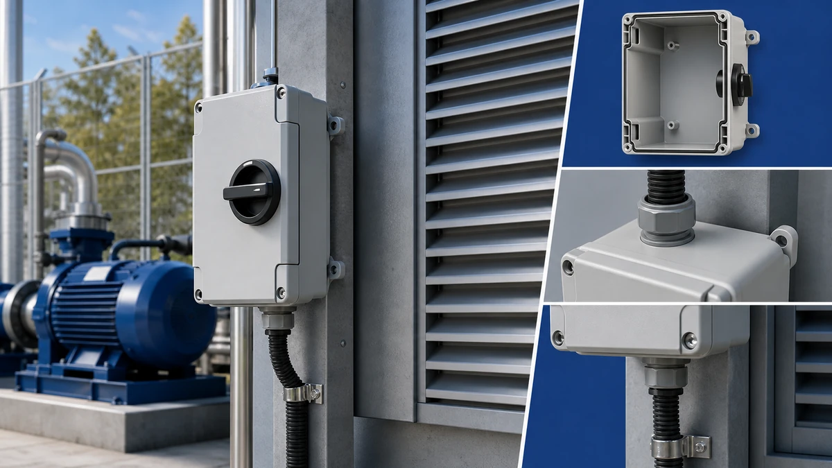
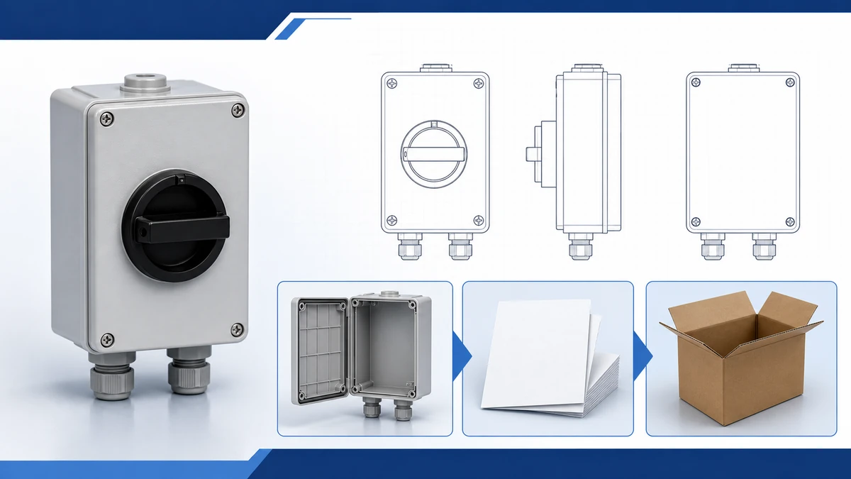
Start with isolation duty, load rating, pole arrangement, and installation environment before selecting a box route.
The enclosure rating depends on the complete installed assembly, including cable entry, gasket, handle, and mounting condition.
Confirm the model code, drawing, and certificate scope before purchase.
An SH30 weatherproof isolator switch box is a factory-assembled unit combining an SH30-series rotary cam switch with a sealed enclosure rated for outdoor and moisture-exposed installations. It provides verified load isolation across a 20A to 125A current range at voltages up to 690V AC, meeting IEC 60947-3 requirements for switch-disconnectors. This guide covers how the mechanism works, how to select the correct frame and pole count, where the device is applied across industries, and what installation steps protect both performance and ingress protection integrity. Engineers, panel builders, and maintenance teams will find actionable specification and wiring guidance throughout.
What Is an SH30 Weatherproof Isolator Switch Box?
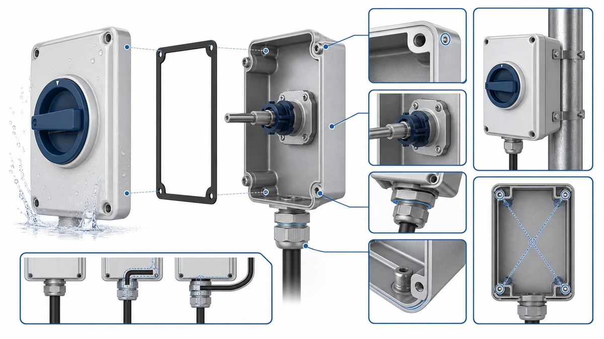
The SH30 weatherproof isolator switch box integrates two engineered elements into one field-ready unit: an SH30-series rotary cam switch mechanism and a sealed thermoplastic or polycarbonate enclosure. The cam switch operates through a precision disc that rotates when the external handle is turned, engaging or disengaging silver-alloy contact bridges across all poles simultaneously. That simultaneous multi-pole disconnection is what qualifies the device as an isolator under IEC 60947-3:2020+AMD1:2025, the IEC standard that applies to switches, disconnectors, switch-disconnectors, and fuse-combination units for distribution and motor circuits, with rated voltage up to 1000V AC or 1500V DC.
The enclosure gasket system creates a continuous seal between the cover and body, maintaining ingress protection after each handle actuation. In outdoor distribution boards, motor feeder circuits, and rooftop PV AC isolation points, the isolator is typically positioned at the incoming supply so service personnel can establish a verified de-energized state before opening downstream equipment.
For a broader context on how rotary cam mechanisms work across different product families, the rotary cam switch range explains the underlying contact platform this box-mounted variant is derived from.
SH30 Weatherproof Isolator Switch Box Basics for 20A to 125A Loads: engineering anatomy reference for technical selection.
How the SH30 Isolator Works: Internal Contact Mechanism and Arc Control
Understanding the internal geometry explains why the SH30 reliably breaks current without damaging the contacts it depends on for the next operation.
Rotary Cam Contact Operation
When the operator turns the SH30 handle, a precision-machined cam disc rotates against a set of stationary contact carriers inside the switch body. At the OFF position, the cam profile forces the moving contact bridge away from the stationary contact pads, creating a defined air gap. IEC 60947-3 requires that an isolator achieve clearance sufficient to prevent re-strike under the rated insulation voltage. Confirm the exact insulation voltage (Ui) value for your specific SH30 frame and pole count from the product datasheet, as this value varies by configuration.
The rotary action also produces a wiping motion across the contact faces during opening and closing, which mechanically clears surface oxides and helps maintain contact resistance within an acceptable range across the rated service life.
Arc Suppression During Load Breaking
When a circuit carrying 20A to 125A AC is interrupted, an electric arc forms between separating contacts. In an industrial motor isolation scenario, the inductive energy stored in the motor windings sustains this arc momentarily after the contacts begin to part. The SH30 addresses arc energy through two coordinated mechanisms.
Contact geometry. The cam profile drives a rapid contact separation velocity, reducing arc duration by minimizing dwell time in the low-gap zone where arc re-ignition is most probable.
Arc runner and chamber design. Molded arc chambers channel the arc column away from the main contact faces and into segmented splitter plates. The plates cool the arc plasma and raise its voltage requirement above the circuit driving voltage, forcing extinction. Shorter arc duration and higher extinction voltage from splitter plate cooling both reduce total arc energy, protecting contact surfaces from erosion over the rated electrical endurance. Endurance figures are evaluated under the applicable IEC 60947-3 utilization category conditions; confirm the rated number of load-breaking operations for your specific frame from the SH30 datasheet.
In a typical industrial feeder isolation application, the SH30 is positioned at the incoming supply of a sub-distribution board where maintenance teams require a verifiable OFF state before working on downstream equipment. The visible rotary position indicator provides the confirmation that IEC 60947-3 demands of a disconnecting device.
Field guidance on arc control:
Never actuate an SH30 in the ON-to-OFF direction while the load is under fault current. Isolators are rated for normal load breaking, not short-circuit interruption. An upstream fuse or circuit breaker must handle fault protection.
After a suspected arc event indicated by unusual smell or discolored handle markings, inspect contact faces through the terminal openings before returning the isolator to service.
In high-cycling applications, schedule contact resistance checks at intervals appropriate to the operating frequency. A measurable increase in resistance on any pole relative to the as-installed baseline value indicates progressive contact erosion.
Specifying the correct utilization category at the outset — AC-23A for motor loads rather than AC-22A — ensures the arc chamber geometry matches the actual inductive energy the circuit presents at each operation.
For further background on how the load isolator category relates to circuit protection philosophy, the article on what a load isolator switch is provides a useful reference before selecting between isolator types.
SH30 Key Components: Enclosure, Contacts, Handle, and Terminals
Four integrated subsystems define the SH30 performance envelope. Understanding each one helps engineers specify the right variant before committing a panel build.
Enclosure Body
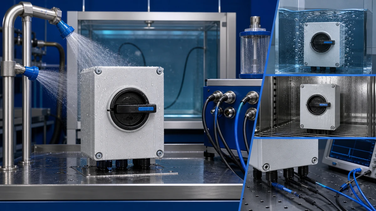
The enclosure is molded from UV-stabilized polycarbonate or glass-fiber-reinforced thermoplastic, providing structural rigidity and dielectric isolation between live parts and the external environment. Depending on the variant, the enclosure achieves IP65, IP66, or IP67 ingress protection per IEC 60529. IP66 resists powerful water jets from any direction; IP67 adds a rating for temporary submersion. A compression-fit gasket on the cover maintains the seal across repeated open-and-close cycles. Confirm the exact IP rating for your selected SH30 variant from the enclosure datasheet, as ratings differ between frame sizes and cable entry configurations.
In outdoor installations such as rooftop PV arrays or dockside distribution panels, this sealed construction prevents moisture ingress that would otherwise accelerate contact oxidation and degrade insulation resistance over time.
Contact Assembly
Inside the enclosure, the SH30 uses a rotary cam-style contact mechanism drawn from the SH30 rotary cam switch platform. Contacts use a silver-tin oxide alloy selected for its resistance to arc erosion and contact welding under inductive load switching. Contact resistance and rated thermal current values are confirmed per the product datasheet for each frame. The mechanism is rated under IEC 60947-3 for making and breaking capacity, utilization category, and mechanical endurance.
Operating Handle and Padlock Facility
The external rotary handle translates angular motion to the internal cam shaft without breaching the enclosure seal. Most SH30 configurations include a padlock hasp accepting a standard lock shackle, supporting lockout/tagout (LOTO) procedures required by maintenance safety protocols. Acceptable shackle diameter range is confirmed from the specific enclosure drawing. The handle position — ON or OFF — is visible at a distance through color contrast or labeled indicators molded into the cover.
Input and Output Terminals
Screw-clamp or bolt-type terminals accept copper conductors sized for the rated frame current. Terminal conductor capacity scales with frame rating; for example, a 63A frame typically accommodates conductors up to 25 mm2 and a 125A frame typically accommodates larger cross-sections — confirm the exact terminal conductor range from the SH30 product datasheet for your pole and frame selection before sizing cables. Terminals are phase-labeled to reduce wiring errors during installation.
SH30 Weatherproof Isolator Switch Box Basics for 20A to 125A Loads: test and measurement reference for technical selection.
Selecting the Right SH30 Rating: 20A to 125A Load Matching Guide
Choosing a current rating is systematic when the load type, operating current, and circuit topology are defined clearly before entering the catalog.
SH30 Load-to-Rating Comparison Table
Load Type
Typical Load Current
Suggested SH30 Rating
Pole Configuration
Notes
Single-phase residential HVAC
16 to 20A
20A
2-pole
Compact surface-mount enclosure
Three-phase light motor (up to 7.5 kW)
18 to 32A
32A
3-pole
Standard enclosure size
Three-phase pump or compressor (up to 15 kW)
30 to 50A
63A
3-pole
Standard to medium enclosure
Commercial air handling unit
45 to 80A
80A
3-pole
Medium enclosure
Industrial feeder or large motor (up to 37 kW)
70 to 100A
100A
3-pole + N
Large enclosure
Heavy-duty distribution feeder
100 to 125A
125A
4-pole
Large enclosure
All values in this table are application guidance only. Confirm the final rating against the load nameplate full-load ampere (FLA) value, the applicable continuous load derating rule in your regional standard, and the confirmed SH30 datasheet for the frame you are ordering.
How to Apply the Table to Your Circuit
A standard derating practice applies a 125% multiplier to continuous loads, meaning an 80A continuous load requires a switch rated at 100A minimum. Verify the applicable continuous load clause in your regional IEC or national standard before finalizing selection.
For three-phase motor loads, select a 3-pole configuration so all live conductors are interrupted simultaneously, satisfying IEC 60947-3 isolation requirements. When a neutral conductor must also be switched — common in TN-S distribution systems at higher current levels — a 4-pole layout is appropriate. Enclosure size scales with busbar and terminal dimensions; confirm minimum creepage distances under the selected IP rating from the enclosure dimensional drawing.
For applications involving solar DC circuits where string current and open-circuit voltage define the switch selection, confirm the utilization category — AC-23A for motor loads, AC-22A for mixed resistive-inductive loads — before finalizing the model route. Understanding the IEC 60947-3 standard framework helps frame these decisions; the published specification is available from the IEC webstore.
Rating selection guidance for field engineers:
When the nameplate FLA sits within 5 percent of a frame current boundary — for example, 29A against a 32A frame — step up to the next rating. Thermal cycling at the rating ceiling accelerates gasket aging faster than the contact mechanism itself.
For variable-speed drive (VSD) output-side isolation, treat the isolator as an AC-22A device even when the motor nominally classifies as AC-23A. VSD output harmonics can sustain arcs longer than a sinusoidal supply at equivalent RMS current.
In coastal or high-humidity sites, specify IP67 over IP65 from the outset. The marginal enclosure cost is far lower than a service call caused by moisture-induced contact tracking at 63A or above.
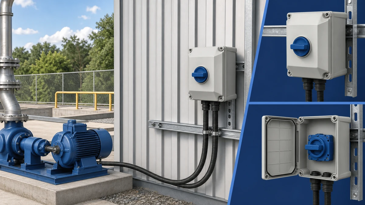
SH30 Weatherproof Isolator Switch Box Basics for 20A to 125A Loads: application context reference for technical selection.
Where SH30 Isolator Switch Boxes Are Used: Applications Across Industries
The rated current range and sealed construction make the SH30 relevant to a wider cross-section of applications than most engineers initially consider.
Commercial Rooftop HVAC and Air Handling Units
Packaged rooftop HVAC units typically draw 20A to 63A at 415V AC three-phase. An SH30 isolator box mounted adjacent to the unit provides a visible off-state for service personnel, satisfying local isolation requirements referenced in IEC 60364-4-46 covering isolation and switching. The weatherproof enclosure prevents moisture ingress during rain or pressure-washing of rooftop plant areas.
Industrial Pump and Motor Stations
In water treatment facilities, irrigation pump stations, and process plants, motors in the 11 kW to 37 kW range require a disconnection means upstream of the starter or variable-speed drive. In a typical pump station layout the SH30 isolator box is installed at the incoming cable entry point — often on a structural steel post — so operators can create a defined off-state before opening the control panel, even in wash-down or splash-prone environments.
Construction Sites and Temporary Power Distribution
Temporary site power boards supplying loads up to 100A at 240V or 415V are regularly exposed to dust, rain, and mechanical impact. The SH30 polycarbonate enclosure provides the ingress protection needed for these conditions. Confirm the applicable IEC or regional standard governing temporary construction site electrical installations for specific isolator requirements in your jurisdiction.
Solar PV AC Isolation Points
The AC output from string inverters — commonly 20A to 63A per unit — requires a dedicated AC isolation point separate from the DC-side disconnection. The SH30 serves this role at the inverter AC output terminal in rooftop and ground-mounted systems, particularly where the switchboard is not within direct line of sight of the inverter.
Food Processing and Agricultural Machinery
Equipment operating in high-humidity washdown environments — including conveyors, refrigeration compressors, and irrigation drives — relies on sealed construction to maintain dielectric integrity after repeated exposure to cleaning agents and condensation. Load types in these settings range from 32A resistive heating circuits to 100A motor loads, all within the SH30 frame range.
Installation, Wiring, and Safety Checklist for SH30 Switch Boxes
A correctly specified SH30 will underperform if installation practice introduces avoidable failure modes. The sequence below addresses the issues most commonly traced back to field handling.
Pre-Installation Checks
Before mounting the enclosure, confirm three items against the circuit documentation.
Verify the SH30 model rating matches the load. The internal mechanism is available in frames covering 20A through 125A; confirm the nameplate current and utilization category (AC-23A for motor loads or AC-22A for mixed resistive and inductive loads).
Check that operating voltage does not exceed the rated insulation voltage Ui of the selected frame. Values typically reach up to 690V AC; confirm against the product datasheet for your specific frame.
Inspect the enclosure gasket and cable gland threads for transport damage before proceeding.
Mounting and Cable Entry Sequence
Mount the enclosure on a flat, vibration-stable surface using all fixing points. Confirm mounting hardware torque values from the manufacturer dimensional drawing rather than applying an arbitrary value.
Select cable glands sized for the actual cable outer diameter. A mismatched gland is the most common source of IP rating failure in field installations.
Route conductors so that phase and neutral cables maintain the minimum creepage distance specified in the enclosure drawing between adjacent terminals inside the box.
Wiring Sequence
Connect the line-side (incoming supply) conductors to the upper terminals first.
Connect the load-side (outgoing) conductors to the lower terminals.
Torque all terminal screws to the value specified on the terminal datasheet. Under-torqued connections cause resistive heating at rated current, which accelerates insulation degradation and can compromise IP integrity over time.
Final Safety Verification
Confirm rotary handle operation: the OFF position must achieve full contact separation on all poles simultaneously. The visual indicator must align with the OFF marking before any downstream work begins.
Apply an insulation resistance test between phases and between phase and earth. Confirm the applicable field test voltage and minimum acceptable insulation resistance for your installation category from the IEC 60364 series relevant to your jurisdiction.
Close and latch the enclosure lid, verifying gasket compression is uniform around the full perimeter before energizing.
For applications in corrosive or coastal environments, confirm cable jacket compatibility with the local chemical exposure classification before finalizing cable gland selection.
SH30 Weatherproof Isolator Switch Box Basics for 20A to 125A Loads: supply handover reference for technical selection.
How Shieldhz Configures and Supports SH30 Isolator Switch Box Orders
Shieldhz is the export brand of Zhejiang Shihe Electric Co., Ltd., founded in 2014 and operating from a manufacturing facility of over 5,000 square meters in the Yueqing electrical components manufacturing cluster, Zhejiang Province. The company employs more than 100 staff and operates over 40 production and testing machines. The quality management system is certified to ISO 9001, and products are available with CE, TUV, UL, UKCA, CCC, CB, and RoHS documentation depending on destination market and product configuration.
For each SH30 inquiry, Shieldhz reviews the following buyer inputs to route the correct model into production rather than a generic catalog frame.
Load rating and utilization category. Buyers provide the operating current (20A to 125A), supply voltage, and IEC 60947-3 utilization category — AC-21A, AC-22A, or AC-23A — so the correct contact program and arc chamber geometry are confirmed for the load type.
Pole count and contact program. The pole count (2-pole, 3-pole, or 4-pole) is confirmed against the circuit topology. For motor or feeder circuits requiring neutral switching, the 4-pole contact table is reviewed against the wiring diagram before production release.
Enclosure IP rating. Most SH30 configurations target IP65 or IP66 for outdoor and weatherproof duties; IP67 is confirmed where the application description indicates temporary submersion risk or aggressive washdown cycles.
Terminal and wiring requirements. Conductor cross-section, cable entry direction, and terminal torque specifications are reviewed against the confirmed frame drawing to verify internal clearance and creepage distance compliance.
Certification and documentation package. Shieldhz prepares a documentation set aligned to the destination market: confirmed model datasheet, wiring diagram, dimensional drawing, ingress protection test records per IEC 60529, and switching performance records per IEC 60947-3 as applicable to the frame and pole count being supplied. Documentation is built from the specific model configuration, not assumed from a generic series rating.
To start an inquiry, provide the nominal current in amperes, supply voltage, number of poles, installation environment description including the required IP rating, and any regional certification requirement. The SH30 rotary cam switch product page lists available ratings and pole options that form the basis of the isolator box configuration, and the what is IEC 60947-3 reference page provides additional background on how utilization categories and rated characteristics are verified for switch-disconnector applications.
Frequently Asked Questions
What does IP65 mean on an SH30 isolator switch box?
IP65 indicates that the enclosure is fully protected against dust ingress and can withstand low-pressure water jets from any direction, as defined by IEC 60529. This rating makes the SH30 suitable for outdoor mounting and rooftop installations where rain and hosing are routine. Variants rated IP66 or IP67 provide resistance to more powerful jets and, at IP67, temporary submersion respectively. Confirm the exact rating for your model from the product datasheet before specifying for a high-exposure site.
Can the SH30 be used to break a motor circuit under load?
Yes. The SH30 is available in configurations rated for AC-23A duty, which covers making and breaking motor loads including the higher inductive currents associated with running and stopping conditions. Always confirm the utilization category on the product datasheet matches your specific motor type, circuit voltage, and expected switching frequency before finalizing the selection.
What is the difference between a 3-pole and a 4-pole SH30 configuration?
A 3-pole unit disconnects all three live phase conductors simultaneously, satisfying IEC 60947-3 isolation requirements for most three-phase circuits. A 4-pole unit adds simultaneous disconnection of the neutral conductor, which is required in certain TN-S distribution systems and in some regional wiring codes. Confirm whether neutral switching is required in your jurisdiction before selecting the pole count.
How often should an SH30 isolator switch box be inspected in outdoor service?
A practical maintenance interval for most outdoor installations is every 12 months, covering gasket condition, terminal torque confirmation, and a contact resistance check relative to the baseline recorded at commissioning. Sites with high UV exposure, salt-laden air, or repeated chemical washdown may warrant a six-month cycle. Adjust the interval based on observed condition at each inspection rather than applying a fixed schedule universally.
Is a separate circuit breaker still required when an SH30 isolator is fitted?
Yes. An isolator provides safe disconnection for maintenance access but is not rated to interrupt fault currents. An upstream overcurrent protective device — fuse or circuit breaker — must remain in the circuit to handle short-circuit and overload conditions. The SH30 and its upstream protective device are complementary, not interchangeable.
What certifications does the SH30 carry for export projects?
CE marking and CCC certification are standard options for the SH30, with RoHS compliance documentation also supported. TUV, UL, UKCA, and CB documentation are available depending on the product configuration and destination market. Buyers should specify the destination market and applicable standards at the inquiry stage so Shieldhz can confirm which certificates apply to the exact frame, pole count, and enclosure variant being supplied.
Can SH30 isolator switch boxes be used on the AC output side of a solar inverter?
Yes. The SH30 is suited to AC isolation at inverter output points for rooftop and ground-mounted PV systems, where it is typically rated at 20A to 63A depending on inverter output current. Confirm that the utilization category, rated insulation voltage, and enclosure IP rating match the inverter AC output specifications and the physical installation environment before ordering.
Shi, Muxi
Shi, Muxi writes Shieldhz technical articles for industrial control and electrical component buyers, covering rotary cam switches, isolator switches, PV DC disconnects, push buttons, indicator lights, waterproof enclosures, and terminal blocks. The articles are based on Zhejiang Shihe Electric Co., Ltd.'s manufacturing and export experience, with practical emphasis on model selection, datasheets, drawings, certifications, IP ratings, and inquiry details buyers should confirm before ordering.