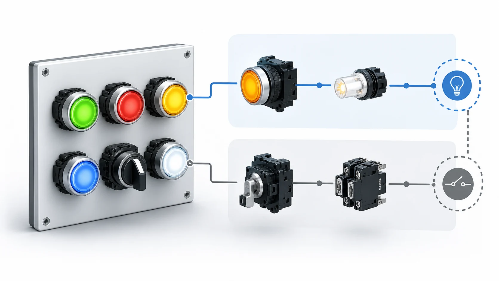
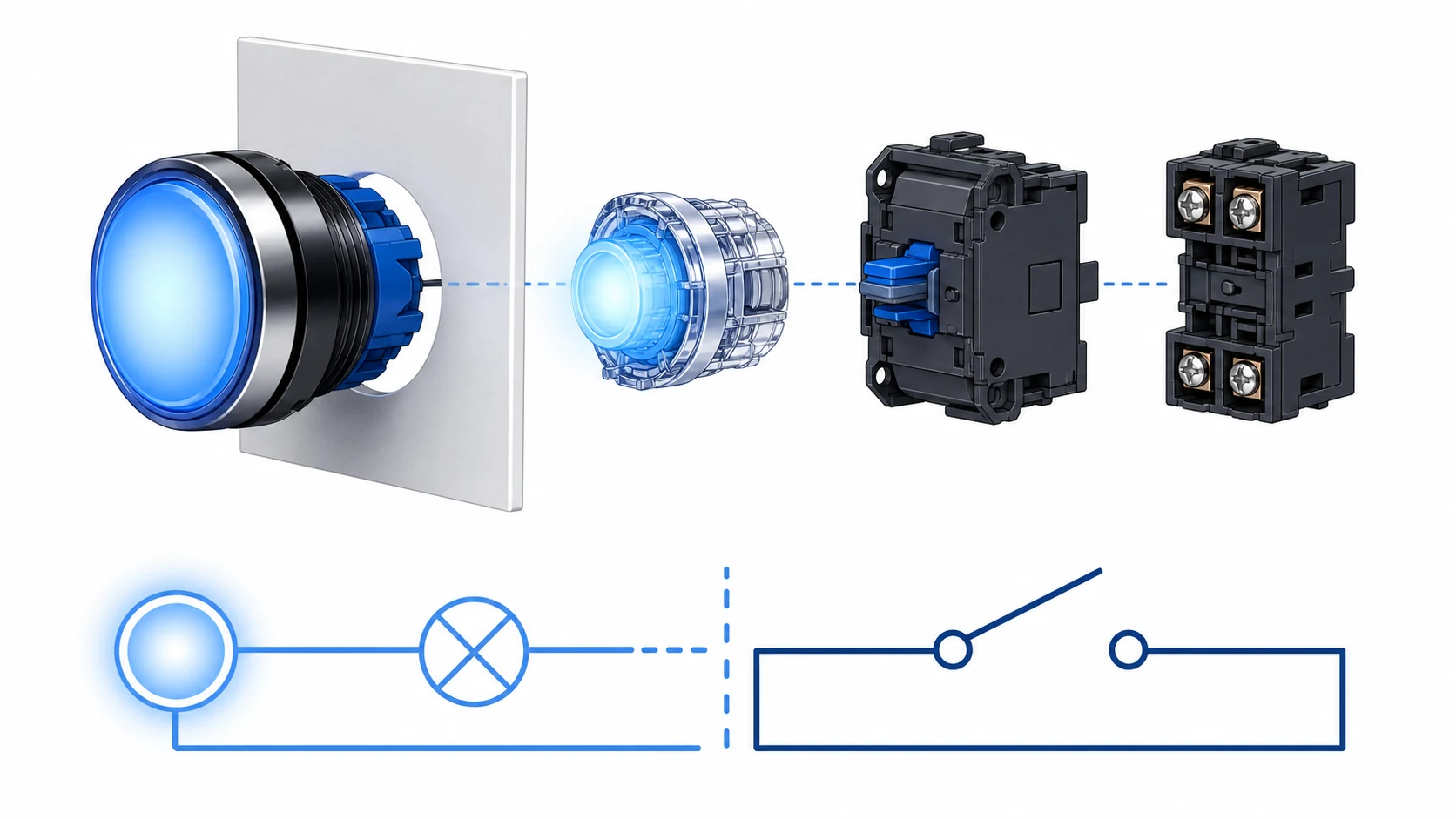
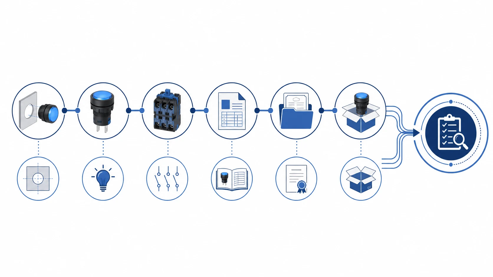
An illuminated push button combines an operator, a lamp or LED module, and one or more contact blocks. It is specified by more than the visible colour. A panel builder needs to confirm the control function, lamp voltage and supply type, lens colour, mounting size, contact arrangement, environmental condition, and the documentation for the exact configured model. Treating every illuminated button as interchangeable can produce a lamp that does not match the panel supply or a contact arrangement that does not match the circuit.
Choose the lamp function before choosing the colour
First decide what the light is intended to communicate. An illuminated operator can show that a circuit is energised, a machine is available, a mode is selected, an instruction is active, or an operator should take an action. The meaning must come from the approved panel legend and project convention. Red, green, amber, blue, and white are common lens colours, but a colour alone does not create a universal safety meaning. Use the site and machine documentation to define the intended indication.
Next decide whether the lamp is part of the push button itself or whether a separate pilot light would give a clearer indication. A lit START operator can be useful where the control action and status are intentionally related. A separate indicator can be better when the status comes from another device, such as a contactor auxiliary contact, PLC output, or fault relay. Keep the functional description clear so an operator does not mistake a lamped button for proof that a load is running.
Specify the meaning of the illuminated operator before selecting the lens and lamp configuration.
Match LED voltage and supply type to the control circuit
Illuminated push buttons are offered with different lamp voltage families. A 24 V DC control circuit needs a lamp module intended for that supply; a 110 V or 220 V AC circuit needs a suitable alternative. Do not assume that an LED module covers every voltage merely because the front lens looks identical. Check the datasheet for rated voltage, AC or DC compatibility, polarity requirements where applicable, and the approved wiring arrangement.
For control panels that use both AC and DC auxiliary supplies, identify the source at the actual lamp terminals. It is possible for the contact circuit and the lamp circuit to be different parts of the control scheme. Record both in the bill of materials and schematic. A correctly selected contact block cannot compensate for the wrong lamp module, and a correctly illuminated lens does not prove that the command contact is wired as intended.
Voltage, brightness, and heat behaviour are configuration-dependent. Ask for the current drawing and data sheet for the selected model, especially where the panel operates in high ambient temperature, direct sunlight, vibration, or a wet or dusty enclosure. The installed assembly, not a generic family statement, determines the final suitability.
Select the contact blocks separately from the lamp module
The lamp assembly provides the visual signal. The contact blocks provide the electrical command. A momentary START button may use a normally open command contact, while a STOP function may use a normally closed path. An illuminated operator can be combined with different contact arrangements, so the required circuit function must be selected from the schematic rather than from the lens colour or head style.
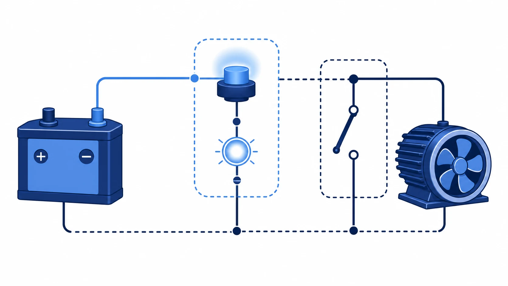
The lamp connection and the command contacts should be reviewed as separate circuit functions.
For a start-stop station, verify what actually energises the illuminated indication. It may be supplied whenever the panel is live, only while the button is pressed, after a contactor picks up, or from a PLC status output. These choices create very different operator messages. The NO and NC contact guide explains the basic contact terms, while the project schematic identifies the correct configuration for the application.
Use colour, marking, and lens style consistently
Colour should support a clear operating convention, not replace it. Pair the lens with durable text or a recognised symbol where the action needs explanation. A green or red lens may be familiar in many industrial settings, but the legend and circuit behaviour still need to be unambiguous. Where colour vision, lighting conditions, or distance could affect recognition, use additional text, shape, position, or a separate audible signal as required by the project.
Lens form also affects readability. A flush, raised, mushroom, or projecting operator can suit different actions and environments. The front form should not be selected only for appearance: it must leave adequate spacing, be readable in the installed panel, and work with any guard, shroud, or enclosure requirement. For emergency-stop applications, use the dedicated emergency-stop product and safety design requirements rather than adapting an ordinary illuminated push button.
Check mounting, sealing, and panel integration
Confirm the panel cutout, panel thickness range, contact-block clearance, wiring bend space, and any required anti-rotation feature. A 22 mm modular arrangement is common in control panels, while metal push buttons can use different diameter families and mounting details. The correct mounting ring and sealing component are part of the installed assembly. The product drawing should be checked before drilling or changing an existing door.
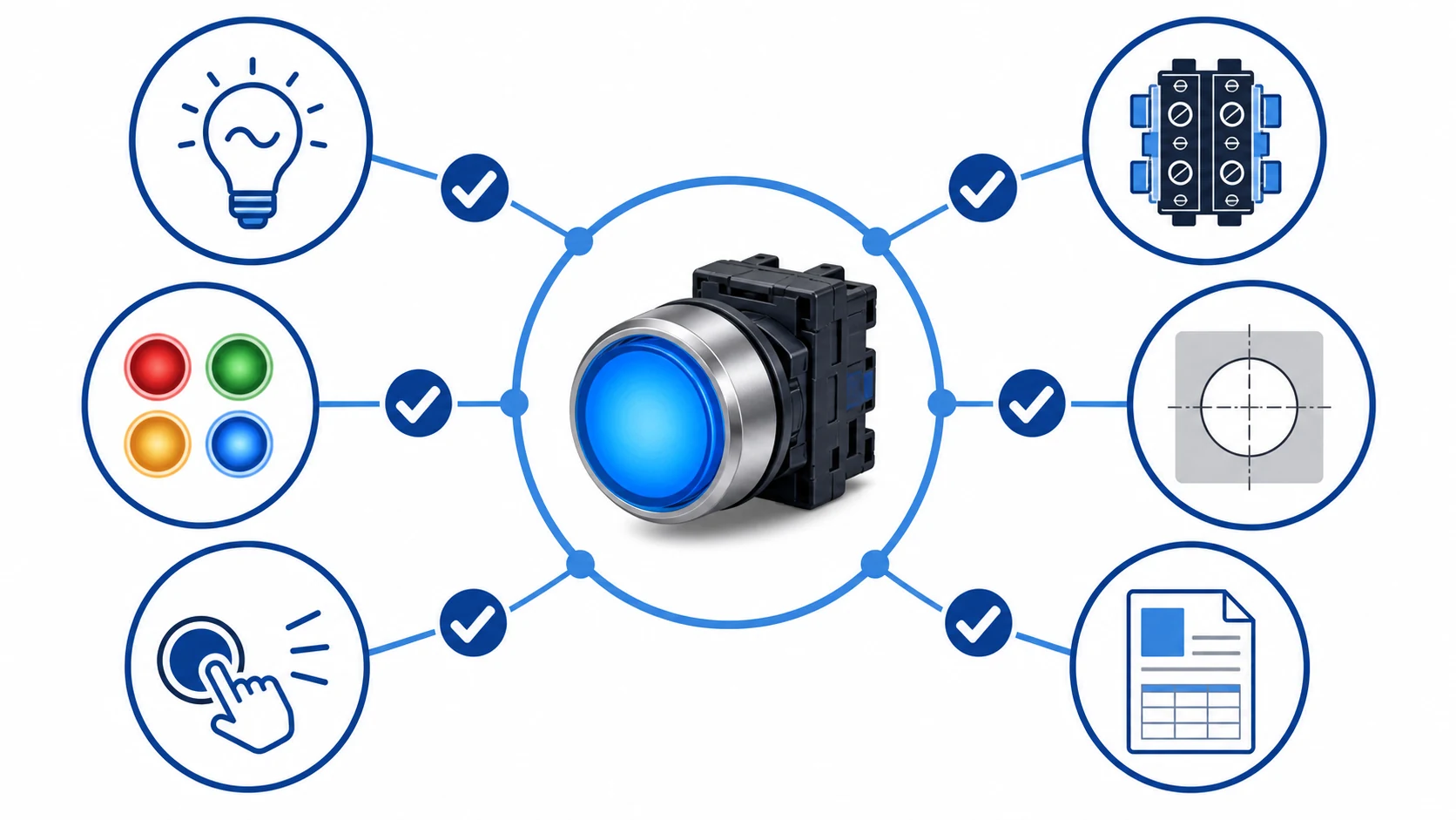
Verify lamp supply, contacts, cutout, spacing, and enclosure condition together.
For washdown, outdoor, or high-dust panels, do not declare an IP level from the operator head alone. The final protection depends on the exact operator, gasket, panel preparation, mounting torque, cable entry, and enclosure. Use the manufacturer drawing and the completed assembly information. The IP rating guide is useful background when reviewing the environment, but it is not a substitute for the exact product documentation.
Build a complete illuminated-push-button specification
Item to specify
Why it is needed
Required operator action
Determines momentary, maintained, or special operating behaviour.
Contact programme
Ensures the command path matches the schematic.
Lamp voltage and AC/DC source
Matches the LED module to the available supply.
Lens colour and legend
Creates a clear, approved operator message.
Cutout and panel thickness
Confirms physical mounting compatibility.
Enclosure condition
Guides sealing and installed-assembly review.
Required documents
Supports drawing, datasheet, and certificate confirmation.
For Shieldhz enquiries, send the panel schematic, lamp supply, lens/legend requirement, contact need, mounting dimension, and environment. Shieldhz can use that information to check the product route, contact blocks, lamp module, drawing, and available documentation for the exact configuration. Start with the push-button and indicator-light range, then request the data sheet and drawing that match the selected assembly.
A complete enquiry includes lamp supply, operator function, contacts, legend, mounting, and environment.
Test the visual indication during commissioning
Before handover, test the lamp and the command circuit independently. Confirm that the correct colour appears in the required condition, that the lens is visible in the installed lighting, and that pressing the operator produces only the intended command. If a PLC or relay drives the lamp, verify the status logic at the source as well as at the front of the panel. A light that remains on after a command has been removed can be misleading even when the contact block operates correctly.
Document the test result with the final drawing revision. Where a replacement button is installed later, verify the lamp supply and contact terminals again; a similar-looking head can use a different lamp module or contact arrangement. Keep spare-part identification tied to the complete configured assembly, including the operator head, LED module, contacts, legend, and mounting accessories.
For industrial equipment, a visible indication supports operation but does not replace lockout procedures, protective devices, safety functions, or qualified troubleshooting. Treat the illuminated push button as one part of a documented control system.
When the required meaning is uncertain, pause the build and obtain an approved legend and circuit decision. That small check prevents a cosmetic choice from becoming an operating error.
Frequently asked questions
Can I use any LED voltage with an illuminated push button?
No. The lamp module must match the actual supply type and voltage stated in the product documentation.
Does the illuminated lens determine the contact type?
No. Lamp modules and contact blocks are separate configuration items. Select the contacts from the circuit requirement.
Is a lit start button proof that the motor is running?
Not necessarily. It depends on how the lamp is wired. Use a documented status source if the indication must confirm a real operating condition.
Can an illuminated push button be used as an emergency stop?
Use a dedicated emergency-stop device and the applicable machine-safety design requirements. Do not substitute an ordinary push button for that function.
What should I send when requesting a quotation?
Send the required action, contacts, lamp voltage, lens colour, legend, cutout, enclosure condition, quantity, and any drawing or document request.
Which reference should guide the final selection?
The exact data sheet and drawing control the configured product. IEC control-device guidance, including IEC 60947-5-1, is a useful standards reference.
Request an illuminated-operator configuration check
Provide the panel details and required indication logic to Shieldhz before ordering. A configuration review can align the lamp module, contact blocks, legend, mounting dimensions, and supporting documents with the intended control-panel function.
Shi, Muxi
Shi, Muxi writes Shieldhz technical articles for industrial control and electrical component buyers, covering rotary cam switches, isolator switches, PV DC disconnects, push buttons, indicator lights, waterproof enclosures, and terminal blocks. The articles are based on Zhejiang Shihe Electric Co., Ltd.'s manufacturing and export experience, with practical emphasis on model selection, datasheets, drawings, certifications, IP ratings, and inquiry details buyers should confirm before ordering.