A GF41 solar DC switch is a photovoltaic isolation device engineered to disconnect DC circuits operating at up to 1500V DC, with current rating confirmed by the selected model code and datasheet. It creates a verifiable open-circuit state between the PV array and the inverter, supporting controlled maintenance, fault response, and emergency shutdown procedures. Governed by IEC 60947-3:2020+AMD1:2025, which applies to switches, disconnectors, switch-disconnectors, and fuse-combination units for rated voltages up to 1000V AC or 1500V DC, the GF41 addresses the specific arc interruption demands that 1500V unidirectional DC loads impose on isolating contacts.
Why 1500V PV Systems Demand a Dedicated DC Isolator
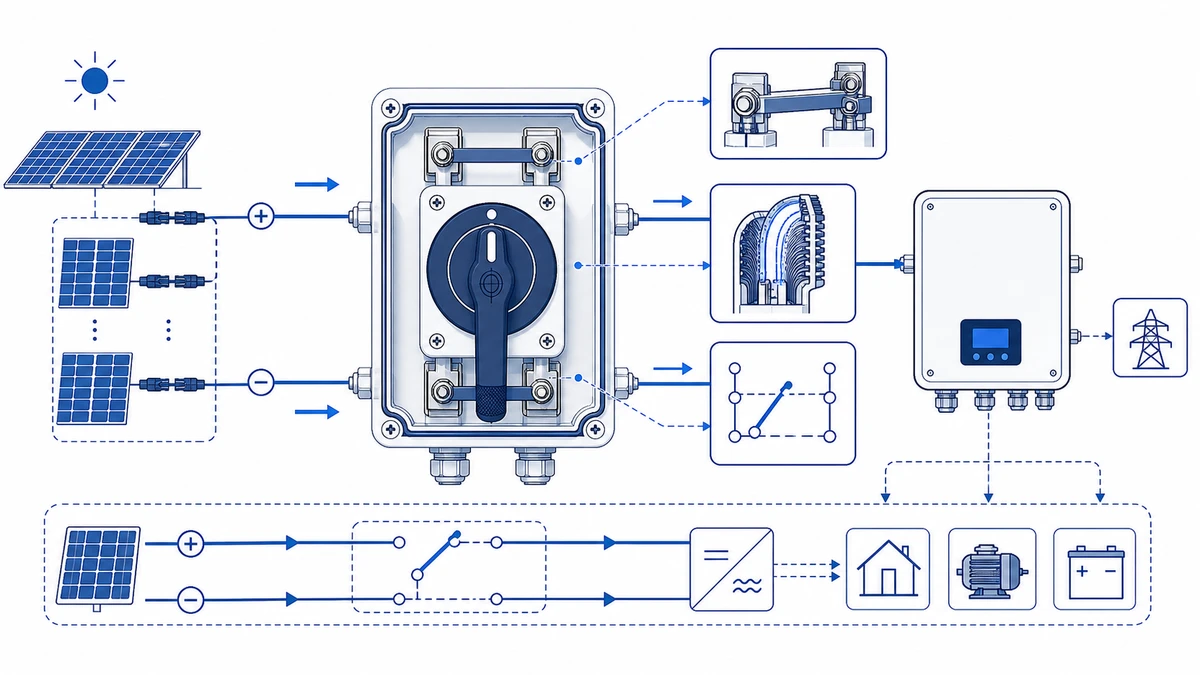
Within a utility-scale or commercial rooftop installation, a GF41 solar DC switch sits at the DC input side of the string inverter or combiner box. The shift from 1000V DC string architecture to 1500V DC has become standard practice in large-scale PV projects because higher voltage reduces conductor losses and permits longer string runs with fewer parallel combiners. However, a 50% increase in system voltage directly raises the arc energy that must be interrupted at the isolator contacts.
Unlike AC isolators, a DC isolation switch must suppress arcs without the natural current zero-crossing that AC waveforms provide. In AC circuits, current crosses zero 100 or 120 times per second at 50 Hz or 60 Hz, giving the arc a periodic opportunity to extinguish. DC circuits carry no such zero crossing. Once an arc ignites between separating contacts in a 1500V PV string, the ionised plasma column is sustained by continuous current flow and will persist until the arc voltage exceeds the source voltage or the plasma is physically disrupted.
For rooftop or ground-mount PV strings operating near maximum open-circuit voltage, selecting an isolator rated below the actual system voltage creates a dielectric breakdown risk. IEC 60947-3:2020+AMD1:2025 addresses this directly through its requirements on rated insulation voltage and impulse withstand voltage. A correctly specified GF41 carries a rated insulation voltage equal to or greater than 1500V DC and an impulse withstand voltage that meets the installation overvoltage category — typically Category III for distribution-level PV infrastructure.
For installations where string voltage remains within the 1000V DC range, the GF40 PV DC isolator switch covers that tier. Once design voltage exceeds 1000V DC, the GF41 is the applicable model within the Shieldhz DC isolation range.
Figure 1. Core concept behind GF41 solar DC switch selection.
How the GF41 DC Switch Achieves Arc Interruption at High Voltage
The GF41 solar DC switch addresses sustained DC arc energy through a multi-stage interruption architecture engineered for unidirectional high-voltage DC loads in photovoltaic systems. Three coordinated physical mechanisms work together to force the arc to extinction before contact erosion becomes self-reinforcing.
Contact Gap Elongation
As the rotary actuator separates the contacts, the moving bridge travels a controlled distance that stretches the arc column. Longer arc columns carry a higher resistive voltage drop, which works against the driving source voltage and progressively reduces arc current.
Magnetic Arc Blowout
A permanent magnet assembly positioned adjacent to each contact chamber generates a transverse magnetic field. By the Lorentz force principle, this field deflects the arc current perpendicular to its path, driving the plasma into the arc runner fins at high velocity and preventing the arc from stabilising in one position.
Segmented Arc Runner Chambers
The arc runner fins divide the single arc column into multiple series sub-arcs. Each sub-arc adds an incremental arc voltage contribution. Across a sufficient number of segments, the cumulative arc voltage exceeds the system open-circuit voltage, forcing current to zero and completing interruption. The number of segments and their geometry are design parameters confirmed in the GF41 product datasheet — do not assume a fixed segment count across all current or voltage variants.
This mechanism aligns with the breaking performance requirements defined under IEC 60947-3:2020+AMD1:2025. For DC isolator switches applied in PV systems, the standard requires verified breaking performance under the DC utilisation category relevant to the rated current and voltage pairing. Confirm the applicable utilisation category against the GF41 datasheet for the specific string configuration before finalising selection.
For a broader explanation of what qualifies a device as a DC switch disconnector in this regulatory context, compare the product marking, datasheet, and installation standard before approving a substitution.
Field note — DC arc interruption in practice:
Always specify the isolator against the temperature-corrected open-circuit voltage, not the STC nameplate value. In cold climates, string voltage can exceed the STC open-circuit voltage enough to invalidate a marginally selected lower-voltage switch. If a GF41 shows signs of contact blackening or slow actuation after a fault event, remove it from service for qualified inspection under the site maintenance procedure; arc erosion is cumulative and cannot be assessed from the external housing alone.
GF41 Key Specifications: Ratings, Poles, and PV System Configurations
The GF41 solar DC switch is engineered specifically for photovoltaic isolation duty, with voltage and current ratings defined to match the high-DC operating conditions found in modern string and central inverter systems.
Voltage, Current, and Pole Configurations
The GF41 is rated for DC system voltages up to 1500V DC, aligning with high-voltage PV string architectures used in utility-scale and commercial rooftop installations. Rated operating current is model-dependent — confirm the exact frame from the selected datasheet, as contact program and wiring configuration affect the continuous current rating.
For a rooftop PV string, engineers commonly select a 2-pole configuration to isolate both positive and negative conductors simultaneously — a requirement under IEC 60364-7-712 for ungrounded DC systems. The GF41 supports 2-pole and 4-pole arrangements, making it adaptable to single-string and dual-string isolation scenarios within the same combiner box or inverter input circuit.
GF41 Specification Reference Overview
Parameter
Reference Value
Maximum System Voltage
1500V DC
Rated Current Range
Model-dependent; confirm variant from datasheet
Pole Configurations
2-pole, 4-pole
Enclosure Protection
IP66 (confirm from product drawing)
Applicable Standard
IEC 60947-3:2020+AMD1:2025
Certifications
CE, TUV (confirm full scope from product documentation)
The IP66 ingress protection rating — dust-tight and resistant to powerful water jets under IEC 60529 — makes the GF41 suitable for outdoor combiner boxes and rooftop mounting environments where moisture exposure is a regular service condition. For installations where enclosure protection requirements go beyond IP66, confirm the GF41 product drawing against the site’s IP specification before ordering. The Shieldhz reference on IP65, IP66, and IP67 differences explains the practical distinctions between those ratings for outdoor PV installation planning.
For comparison within the same DC isolation range, the GF51 PV DC isolator switch covers alternative current tiers. Engineers selecting between models should compare both the rated current frame and the pole count against the specific combiner or string layout requirements.
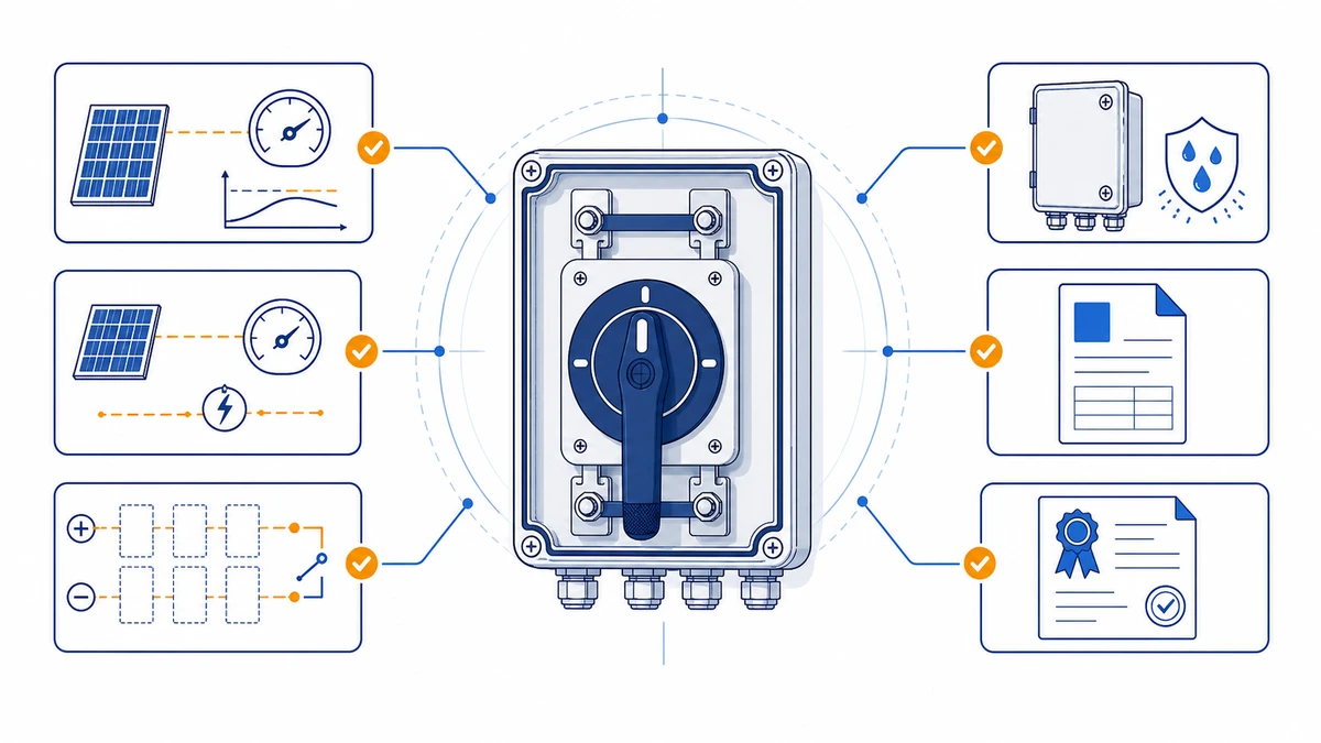
Figure 2. Selection checks should connect DC voltage, string current, pole count, enclosure, cable entry, and documentation.
How to Select the Right GF41 Variant for Your 1500V PV System
Selecting the correct GF41 solar DC switch variant depends on four interdependent parameters: maximum system voltage, string current rating, pole configuration, and installation environment. Confirming each from the system design documentation before consulting the datasheet avoids the most common field under-specification errors.
Parameter 1 — Maximum Open-Circuit Voltage
The selected switch must carry a rated DC voltage equal to or greater than 1500V DC. Confirm the voltage class on the GF41 datasheet matches the IEC 60947-3 rated insulation voltage for the installation. Apply the temperature correction to the module open-circuit voltage at the lowest expected site ambient temperature — not the STC value — before comparing against the switch rating. In cold climates, string voltage at minimum ambient can exceed the STC open-circuit voltage by a measurable margin.
Parameter 2 — String Current Rating
The derated continuous current capability of the switch must exceed the calculated maximum string current. Verify the applicable design factor against the governing installation standard for your jurisdiction, as requirements differ between IEC and NEC frameworks. Confirm this calculated value against the rated current shown in the GF41 datasheet for the chosen pole and frame configuration.
Parameter 3 — Pole Count
Single-string positive and negative isolation typically requires a 2-pole configuration. Combiner-level isolation isolating two strings simultaneously may require a 4-pole layout on a single shaft. A 4-pole GF41 on a single actuator shaft is preferable to two separate 2-pole units in dual-string combiner applications — simultaneous pole actuation eliminates the risk of momentary single-pole isolation under load.
Parameter 4 — Ingress Protection Rating
Outdoor string-level mounting commonly starts with IP65-class protection or higher. Rooftop combiner enclosures in coastal or high-humidity environments often specify IP66 or IP67 per IEC 60529. Confirm the GF41 enclosure rating against the product drawing and request Shieldhz confirmation at the inquiry stage when the site has wash-down, salt-spray, or water-accumulation risk.
For utility-scale ground-mount arrays where string counts and per-string currents exceed the GF41 frame range, comparing the GF41 against the GF51 PV DC isolator switch is advisable, as higher frame ratings may better suit combiner-level isolation duties at elevated current.
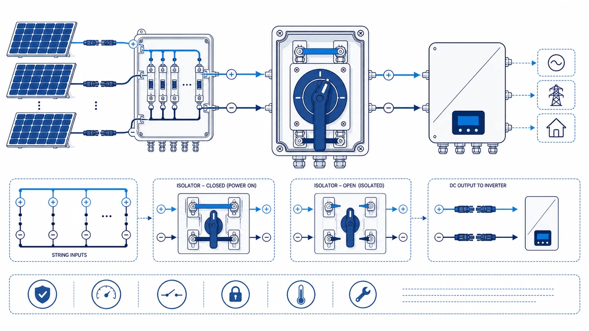
Figure 3. Application wiring context should be verified against the manufacturer contact chart before energizing.
Installing and Wiring a GF41 DC Isolator Switch: Field Best Practices
Correct installation of a GF41 solar DC switch determines whether it performs reliably at 1500V DC system voltage or becomes a latent fault point. The steps below reflect field-verified practice for rooftop and ground-mount PV applications where installers must satisfy IEC 60364-7-712 requirements and site-specific commissioning protocols.
Pre-Installation Verification
Confirm the GF41 rated voltage and rated current match or exceed the string’s temperature-corrected open-circuit voltage and short-circuit current at the lowest expected ambient temperature. Verify the pole configuration against the local installation code and earthing arrangement; many ungrounded PV systems require simultaneous isolation of both positive and negative conductors. Inspect the enclosure IP rating against the site environment before mounting.
Mounting and Orientation
Mount with the actuator shaft and cable entry oriented per the manufacturer’s mounting drawing. Where conduit routing permits, cable entry facing downward reduces water tracking into glands. Confirm panel cutout dimensions from the GF41 mounting drawing before cutting the enclosure — do not rely on nominal or catalog dimensions alone.
Wiring Sequence and Conductor Preparation
Use PV-specific cable rated for the project DC voltage class from the string source through the isolator to the inverter DC input. De-energize and lock out the circuit under the approved site procedure before connecting any conductors. Strip insulation to the terminal manufacturer’s stated strip length, as shown in the datasheet terminal table for the specific frame. Follow the project wiring method and product drawing for line/load orientation instead of relying on a generic connection sequence.
Torque terminal screws to the value specified in the GF41 datasheet for the terminal type and conductor cross-section. Under-torqued connections create resistance heating that is not always visible on thermographic survey until damage has progressed. Over-torqued connections can crack terminal bodies in this frame class.
Post-Wiring Verification
With the switch in the OFF position, confirm insulation resistance of 1 MOhm or greater between poles and between each pole and earth using a DC-rated insulation tester at an appropriate DC test voltage. Confirm actuation from OFF to ON and back to OFF produces a clear mechanical detent with no unusual resistance. Record the test results in the commissioning documentation package before energising the string.
How Shieldhz Configures and Validates GF41 DC Switches for 1500V PV Projects
Configuring a GF41 solar DC switch for a 1500V PV project requires more than selecting the correct voltage rating from a catalog page. Shieldhz — the export brand of Zhejiang Shihe Electric Co., Ltd., founded in 2014 and operating from a facility of over 5,000 square meters in the Zhejiang/Wenzhou/Yueqing manufacturing region — runs each GF41 order through a structured technical review before production and shipment confirmation.
Application Parameter Collection
Shieldhz requests the following inputs from the buyer at the inquiry stage: maximum system open-circuit voltage, string operating current, number of poles required, intended mounting orientation, enclosure IP requirement, and any local installation standard or authority having jurisdiction requirement the project must satisfy. For 1500V DC PV systems, the rated insulation voltage stated on the datasheet must be verified against the actual string open-circuit voltage with an appropriate safety margin under IEC 60947-3:2020+AMD1:2025.
Contact Program and Wiring Diagram Confirmation
Shieldhz confirms the contact table and switching sequence against the declared application. For a rooftop combiner application, the GF41 is commonly configured in a 2-pole on-off arrangement to isolate both positive and negative conductors simultaneously. A wiring diagram and mounting drawing are provided to the buyer for pre-installation review so that panel cutout and conductor entry can be confirmed before the enclosure is fabricated or ordered.
Documentation and Certificate Review
Before shipment, Shieldhz prepares the documentation package applicable to the destination market. This typically includes the product datasheet, a test report referencing the applicable IEC standard, and the certificates required for market entry — CE, TUV, CB, RoHS, or others depending on project location. Buyers specifying projects in markets that require third-party PV component certification should state this requirement explicitly at the inquiry stage so the correct certificate scope can be confirmed. For commercial and utility PV procurement, self-declaration documents may not be accepted where the project specification calls for independent test evidence.
With over 100 employees and more than 40 dedicated production and test machines, Shieldhz maintains in-house production capability to support both standard GF41 configurations and application-specific contact or enclosure variants. Inquiry inputs — including system voltage, current, pole count, IP requirement, and destination standard — allow Shieldhz engineers to return a confirmed datasheet, wiring diagram, and documentation scope before the order is placed.
For background on what the IEC 60947-3 standard requires from a switch in this application class, the published standard is available directly from the IEC webstore. Confirm the exact standard edition and utilization category from the model-specific certificate before using a GF41 as a substitute in a 1500V PV system.
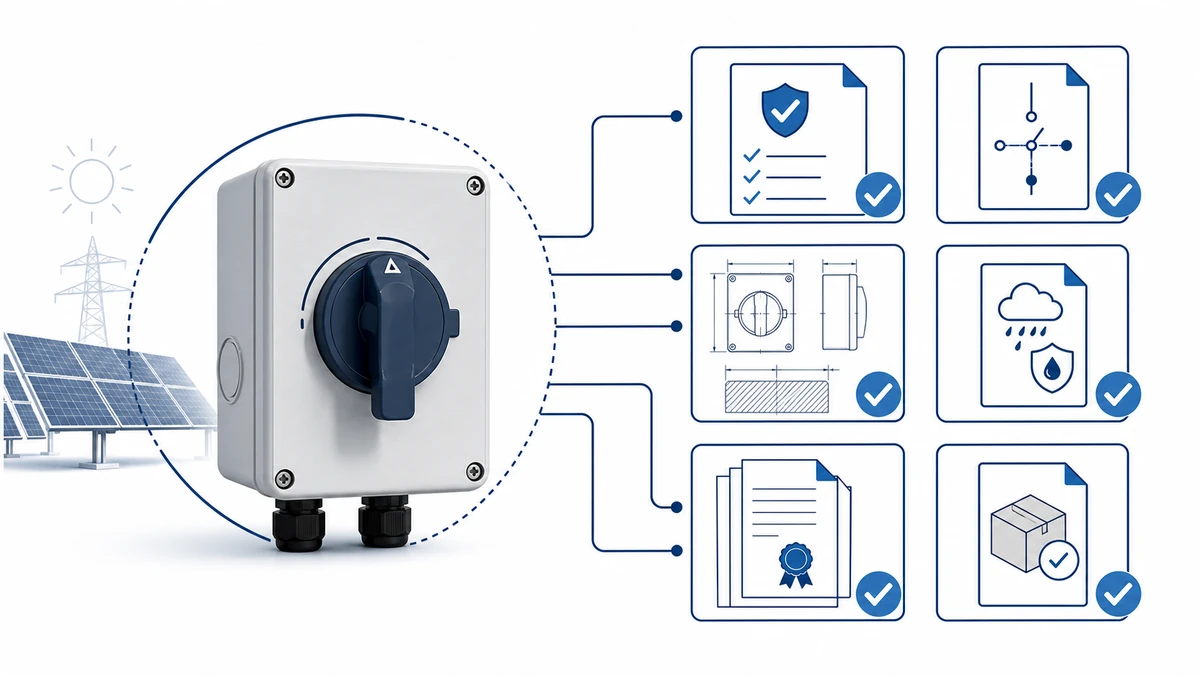
Figure 4. A complete inquiry should include rating, contact sequence, mounting, enclosure, and document requirements.
Frequently Asked Questions
What is the difference between a GF41 and a GF40 DC isolator switch?
The GF41 is rated for DC system voltages up to 1500V, while the GF40 is designed for 1000V DC string architectures — making the GF41 the correct choice for any installation where the temperature-corrected open-circuit string voltage exceeds 1000V DC. Applying the lower-rated GF40 in a 1500V system creates a dielectric breakdown risk at the isolator contacts because the rated insulation voltage and impulse withstand voltage of the GF40 are not validated for 1500V service conditions. Confirm the applicable rated voltage from the product datasheet before substituting one model for the other.
Does a GF41 solar DC switch need to be rated higher than the actual nominal system voltage?
The switch’s rated insulation voltage must meet or exceed the maximum open-circuit voltage of the string at the lowest expected ambient temperature — not just the nominal operating voltage at STC. Because open-circuit voltage rises as module temperature drops, the selected device must be checked against the corrected Voc value rather than a simplified array label. The GF41’s 1500V DC rating is applicable only when the string’s temperature-corrected open-circuit voltage remains within the device’s rated insulation voltage. Always confirm the corrected value from the module temperature coefficient data before finalising selection.
Why do PV DC isolators require a 2-pole configuration in most installations?
Many wiring regulations for ungrounded DC PV systems require simultaneous disconnection of both the positive and negative conductors to achieve a verifiable open-circuit state and reduce touch-voltage hazards. A single-pole isolator can leave one conductor energised relative to ground even in the OFF position. The GF41 supports 2-pole and 4-pole configurations on a single actuator shaft, allowing both conductors to be interrupted simultaneously when that configuration is required.
What IP rating is required for a GF41 installed in an outdoor combiner box?
Outdoor string-level environments commonly use IP65-class protection or higher under IEC 60529, while IP66 provides additional protection against water jet ingress for rooftop or ground-mount installations subject to rain, wash-down, or coastal spray. High-humidity and coastal sites with potential for water accumulation around the enclosure should evaluate IP67, which requires confirmation against the specific GF41 product drawing and a Shieldhz engineering review at the inquiry stage.
How often should a GF41 DC isolator switch be inspected in service?
Inspection intervals depend on local regulations and site maintenance schedules. A practical field approach is to include the isolator in scheduled thermal inspection of the combiner box, where such inspection is part of the O&M plan, and to check for actuation-force changes, contact discoloration, and terminal condition at each planned maintenance visit. Arc erosion is cumulative and is not always visible on the enclosure exterior; if a GF41 has interrupted a fault current or shows signs of slow actuation, follow the site procedure and supplier guidance before returning it to service.
Can a GF41 be used as the main AC-side isolator in a PV installation?
No. The GF41 is designed and rated exclusively for DC load-break duty in photovoltaic systems, where its arc quenching chamber geometry, contact gap, and magnetic blowout assembly are optimised for unidirectional DC current at up to 1500V DC. AC-side isolation requires a device rated and tested for AC breaking capacity under the applicable utilisation category and voltage class. Using a DC-rated isolator in an AC circuit is outside the device’s validated operating envelope and is not permitted under IEC 60947-3.
What documentation should be requested from a GF41 supplier before procurement?
For commercial or utility PV procurement, request model-specific IEC 60947-3 test evidence, the CB scheme certificate if the destination market requires it, the product datasheet showing rated voltage and current under DC conditions, the wiring diagram, and the panel cutout drawing for enclosure integration. Self-declaration compliance documents may be insufficient where the project specification calls for third-party test evidence. For projects requiring TUV certification, confirm that the certificate scope covers the exact GF41 model and pole configuration specified — certificate scope sometimes differs between variants within the same product family.
For GF41 datasheet requests, wiring diagrams, and documentation packages, contact Shieldhz directly through the DC isolator switch product range page or the GF41 solar DC switch product page, providing your string voltage, rated current, pole count, IP requirement, and destination installation standard.
Shi, Muxi
Shi, Muxi writes Shieldhz technical articles for industrial control and electrical component buyers, covering rotary cam switches, isolator switches, PV DC disconnects, push buttons, indicator lights, waterproof enclosures, and terminal blocks. The articles are based on Zhejiang Shihe Electric Co., Ltd.'s manufacturing and export experience, with practical emphasis on model selection, datasheets, drawings, certifications, IP ratings, and inquiry details buyers should confirm before ordering.