The GF51 PV DC isolator switch is a dedicated photovoltaic disconnection device rated for DC circuits up to 1000 V DC, with the current frame confirmed by the selected model code and datasheet. It provides a safe, lockable off-state for PV string and combiner circuits and reaches the field through two distinct installation routes: DIN rail mounting inside a buyer-supplied enclosure, and a factory-enclosed weatherproof assembly for direct outdoor deployment. Choosing the correct route depends on location, ingress protection requirement, string current, and the applicable local installation code. This article explains both routes in full, covers internal architecture, compliance requirements, and installation procedure, and describes how Shieldhz confirms the right model configuration at inquiry stage.
What Makes the GF51 a PV-Specific DC Isolator
Unlike general-purpose AC isolators, the GF51 is engineered for the sustained unidirectional current characteristics of photovoltaic systems. DC arc interruption requires a fundamentally different contact geometry than AC breaking, because DC arcs do not self-extinguish at a natural current zero crossing. The GF51 contact system addresses this through an extended arc path and magnetic blow-out geometry to reliably quench arcs at rated voltage.
For PV string disconnection, the relevant selection parameters are maximum open-circuit string voltage (Voc), maximum short-circuit current (Isc), pole count, preferred mounting route, and the applicable installation standard for the destination market. Confirming all five at inquiry stage prevents substitution errors downstream.
To understand where the GF51 sits within the broader product range, the what is a PV DC isolator switch reference explains the category fundamentals, and the DC isolator switch range provides model-level comparison across the full family.
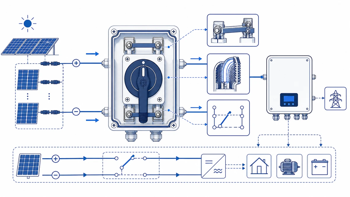
Two Primary Installation Routes
The GF51 reaches the field through two configurations that share the same internal switch mechanism but differ substantially in infrastructure, cost, and environmental performance.
DIN rail route: The bare switch mounts on a 35 mm DIN rail inside an existing inverter cabinet or field enclosure. This route suits system integrators who specify their own IP-rated housing and need to consolidate multiple string disconnects inside a single panel.
Enclosed route: The switch is factory-fitted inside a rated weatherproof box, forming a self-contained assembly with a gland plate and pre-defined cable entry points. This suits rooftop, carport, and ground-mount installations where a standalone, IP-rated disconnect point is required adjacent to the array or at the inverter DC boundary.
DIN Rail Route: Infrastructure, Cost, and Compliance Implications
When to Choose DIN Rail Mounting
The DIN rail route is appropriate where the host enclosure already provides the required ingress protection and ambient temperature control. Indoor inverter rooms, protected AC/DC combiner boxes, and switchroom panel builds are the most common applications. Because the switch itself is a bare device in this configuration, it relies entirely on the host enclosure for environmental protection — a fact that must be confirmed against the enclosure’s IP rating and the thermal load from adjacent components.
Conductor Entry and Terminal Practice
Conductors enter the enclosure via cable glands, and the GF51 terminals accept copper conductors up to the cross-section specified in the model datasheet. Strip length and terminal clamping torque vary by pole configuration and current frame; always read the supplied product drawing rather than applying a default value. Under-torquing causes resistive heating at the terminal interface over time; over-torquing risks cracking the terminal body.
When multiple DIN rail switches share a sealed enclosure under full load, internal ambient temperature can rise substantially above external ambient. Verify the host enclosure’s thermal derating against the GF51’s rated upper operating limit before finalising the layout.
DIN Rail Mounting Sequence
Confirm the 35 mm DIN rail is clean, level, and secured to the backplate before mounting any device.
Press the GF51 rear clip onto the top edge of the rail at a slight angle, then snap the bottom clip down until the latch engages.
Orient polarity correctly before inserting conductors. The positive conductor connects to the marked positive input terminal; reversing polarity in a DC circuit risks sustained arcing because there is no natural current zero crossing to assist extinction.
Strip insulation to the length specified in the terminal datasheet and confirm the exact value from the product drawing before wiring.
Insert each conductor fully and tighten to the torque value stated in the datasheet.
Set the handle to OFF (0) and verify handle position before connecting the upstream DC supply.
Commissioning Checks for DIN Rail Installations
Before energising, confirm all unused terminals are covered or insulated. Any insulation-resistance test should use the voltage, duration, and acceptance threshold defined by the approved commissioning plan and local installation code, not a generic checklist value. Switch to ON only after qualified personnel verify that the output terminal voltage matches the expected string open-circuit voltage at the measured site temperature.
Enclosed Route: Outdoor and Array-Side Deployment
When to Choose the Enclosed Route
The enclosed route is appropriate for any isolator mounted beyond the inverter room boundary or in a location exposed to weather, UV radiation, or condensation cycles. On commercial rooftop projects, the enclosed route should be the default specification for array-side isolators even where a temporary shelter exists; UV degradation and condensation cycling compress the service life of makeshift enclosures within a few seasons.
The enclosed GF51 assembly typically carries an IP65 or IP66 rating per IEC 60529, which governs ingress protection against dust and directed water jets. Where standing water or periodic wash-down is possible, IP66 or IP67 is more appropriate. Confirm the specific IP rating of the selected model code from the product datasheet rather than assuming a family-wide default. For background on how IP protection levels are defined and tested, the IP65 IP66 IP67 reference explains the classification framework.
Environmental Assessment Before Mounting
Verify that the enclosure IP rating matches the deployment zone before ordering. Ambient operating temperature should be confirmed against the GF51 datasheet; direct south-facing surfaces under full solar gain can push enclosure internal temperatures well above the measured external ambient. Where surface temperatures are a concern, maintain clearance around the enclosure base or select a variant with an integrated thermal relief feature if the product range offers one.
Conduit Entry and Sealing Checklist
Orient conduit entries downward or at a 45-degree angle where possible to prevent water tracking along the cable into the entry point.
Use IP-rated cable glands matched to the conduit or cable outer diameter; confirm the gland’s IP rating equals or exceeds the enclosure IP class. A gland rated IP54 will defeat an IP66 enclosure at every cable entry point.
Seal all unused conduit knockouts with rated blanking plugs before final closure — a common oversight that compromises the full enclosure IP class.
Apply conduit sealing compound at transition points in high-humidity or submersible-risk zones, per the applicable local wiring rules for PV systems.
Secure DC string cables close enough to the entry point to prevent mechanical stress on terminal connections, using the spacing defined by the project wiring standard.
Mounting and Orientation Guidance
Fix the enclosure to a structurally sound surface using stainless-steel fasteners rated for outdoor use. Maintain the minimum clearance specified in the enclosure drawing around ventilation features where thermal relief is required. The GF51 operator handle must remain freely accessible for manual isolation without tool removal; this accessibility requirement is addressed by IEC 60947-3:2020+AMD1:2025, which applies to switches, disconnectors, switch-disconnectors, and fuse-combination units for distribution and motor circuits, with rated voltage up to 1000 V AC or 1500 V DC.
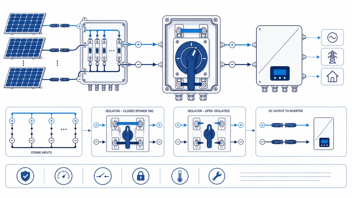
Figure 2. Selection checks should connect DC voltage, string current, pole count, enclosure, cable entry, and documentation.
Route Selection Summary
Criterion
DIN Rail Route
Enclosed Route
Typical location
Indoor / protected panel
Outdoor / array-side
Enclosure IP
Provided by host panel
Self-contained (see datasheet)
Installation cost
Lower per switch
Higher, includes housing
Conductor management
Panel trunking
Gland plate, UV-rated cable
Array-proximity mounting
Not typical
Standard practice
Thermal management
Host panel design
Enclosure clearance and orientation
GF51 Internal Architecture
Understanding the internal assembly helps engineers anticipate both selection constraints and maintenance considerations.
Double-Break Contact Bridge
The GF51 uses a double-break contact mechanism, meaning each pole interrupts the DC circuit at two points simultaneously. This arrangement shares the interruption duty across two contact gaps and improves arc extinction margin at rated DC voltage, where arc control is inherently more demanding than in AC circuits. Contact materials are selected for low contact resistance and resistance to welding under fault current. Confirm the exact contact material grade, rated making capacity, and rated breaking capacity on the model-specific datasheet, as values vary by pole configuration and current frame.
Arc Suppression Chamber
Each pole incorporates a dedicated arc suppression chamber with segmented arc splitter plates. In DC switching, these plates divide a sustained arc into shorter series arcs, raising the total arc voltage above the system EMF and forcing extinction. For PV string applications operating up to 1000 V DC, this geometry is critical — arc energy scales directly with system voltage, and inadequately suppressed arcs accelerate contact erosion and shorten service life.
Terminal Design
Input and output terminals are rated to accept conductors up to the cross-section stated in the model datasheet. Clamping torque and conductor size limits vary by current frame; confirm both from the supplied product drawing before wiring. Tin-plated or silver-plated contact surfaces minimise oxidation in outdoor enclosure environments where humidity cycles are frequent.
IP-Rated Housing Variants
DIN rail variants achieve IP20 as bare devices and rely on the host enclosure for environmental protection. Enclosed and panel-mount configurations reach IP65 or IP66 as stated in the model-specific datasheet. Selecting the correct IP variant is as important as confirming the electrical rating; an incorrectly rated enclosure will pass incoming inspection and fail in service.
Compliance and Standards for PV DC Isolation
The Applicable Standard Framework
Electrical ratings alone do not confirm suitability. The GF51 must satisfy a layered set of IEC and EN requirements before it can be correctly specified in a solar installation.
IEC 60947-3:2020+AMD1:2025 applies to switches, disconnectors, switch-disconnectors, and fuse-combination units for distribution and motor circuits, with rated voltage up to 1000 V AC or 1500 V DC. For the GF51, this standard governs rated making and breaking capacity, utilization category, and the isolation gap requirement relative to the rated impulse withstand voltage. The IEC 60947-3 standard is the primary reference for DC utilization category selection in PV disconnection applications. For additional context on how the standard applies in practice, the IEC 60947-3 application reference provides a practical summary.
Compliance Reference Table
Standard
Scope
Key Parameter for GF51
IEC 60947-3:2020+AMD1:2025
Low-voltage switchgear — disconnectors and switch-disconnectors
Datasheet-defined DC utilization category; rated making and breaking capacity
IEC 60947-1
General rules for low-voltage switchgear
Rated insulation voltage Ui; rated impulse withstand voltage Uimp; temperature derating
IEC 60529
Degrees of protection provided by enclosures (IP Code)
Host-enclosure protection for DIN rail route; IP-rated housing for enclosed route
IEC 62109-1
Safety of power converters for use in PV power systems
Isolation requirements; creepage and clearance distances
EN 50539-11
DC SPD coordination for PV applications
Overvoltage category; coordination with surge protection devices
Critical Numeric Parameters
Two rated values anchor GF51 compliance decisions. Rated insulation voltage Ui must meet or exceed the system’s maximum DC open-circuit voltage, commonly up to 1000 V DC in commercial rooftop and smaller ground-mount strings. Rated impulse withstand voltage Uimp governs creepage and clearance distances between poles and to earth; confirm the specific value from the model datasheet.
Verifying that the selected GF51 variant matches both the pole count and the DC utilization category — not just the voltage rating — is essential before specifying the DIN rail or enclosed route. The utilization category is the most commonly overlooked parameter in competitive substitution; it determines the breaking capacity and must appear explicitly on the bill of materials.
For compliance verification in practice, request the test certificate alongside the datasheet at inquiry stage rather than after the purchase order. A certificate referencing an outdated standard edition can delay project sign-off with the authority having jurisdiction. For export projects, confirm whether CE marking is sufficient or whether a supplementary TUV or CB scheme certificate is required by the local regulator; IEC 60947-3 compliance is a prerequisite for both, but the certifying body differs.
Figure 3. Application wiring context should be verified against the manufacturer contact chart before energizing.
How Shieldhz Confirms the GF51 Model, Route, and Documentation for Your Project
Selecting the correct GF51 variant is straightforward when four buyer-defined parameters are confirmed upfront. Shieldhz — the export brand of Zhejiang Shihe Electric Co., Ltd., founded in 2014 and operating from a 5,000-plus square-metre facility in the Yueqing, Wenzhou region of Zhejiang — works through that confirmation at inquiry stage before issuing any drawing or quotation.
Inputs Shieldhz Requests at Inquiry
When a buyer submits a GF51 inquiry, the Shieldhz engineering team requests the following: maximum PV open-circuit voltage in volts DC, rated string current in amperes, required pole configuration (2-pole or 4-pole), preferred mounting route (DIN rail or enclosed), and the certification package required for the destination market. Common certificate requests include CE, TUV, CB, and UKCA depending on the project geography.
With those inputs confirmed, Shieldhz selects the correct GF51 model code, specifies the contact program appropriate to the string current rating, and identifies whether the DIN rail variant or a pre-wired enclosed assembly suits the installation environment. For rooftop or outdoor combiner-box applications where the isolator is exposed to weather, the enclosed route is normally the more appropriate model path.
Documentation Package Issued Before Order
Rather than issuing a generic family datasheet, Shieldhz provides a model-specific technical package that includes the dimensional drawing, wiring diagram, rated insulation voltage Ui, utilization category, rated making and breaking capacity, and the applicable test certificate referenced to the current standard edition. This allows the buyer’s design engineer or procurement team to verify compliance against the project specification and local grid code before committing to a bill of materials.
Shieldhz holds ISO 9001 quality management certification and supports product-level documentation under CE, TUV, UL, UKCA, CCC, RoHS, and CB schemes as applicable to the specific model and market. Certificate scope and edition should be confirmed at inquiry for each shipment destination.
Explore the GF51 PV DC isolator switch product page for model-level specifications. Submit your system voltage, string current, pole count, and mounting route to receive a confirmed model code, dimensional drawing, wiring diagram, and certificate package for your project.
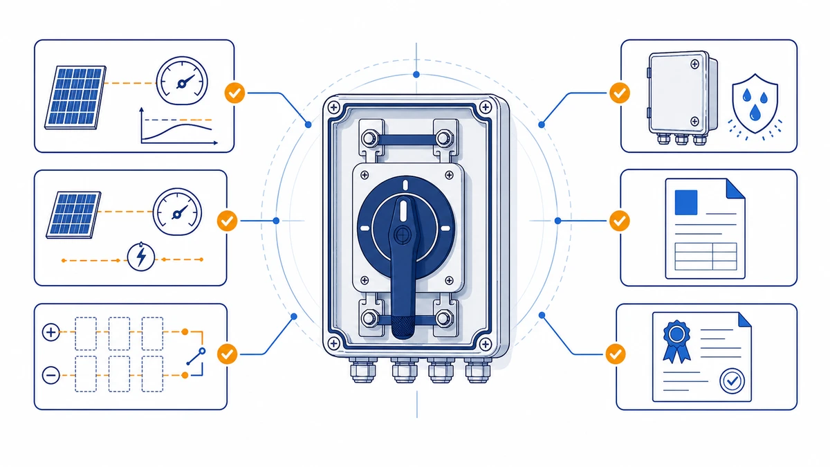
Figure 4. A complete inquiry should include rating, contact sequence, mounting, enclosure, and document requirements.
Frequently Asked Questions
What is the difference between the GF51 DIN rail variant and the enclosed variant?
The DIN rail variant is a bare switch designed to mount inside a buyer-supplied enclosure. It achieves IP20 as a standalone device and relies entirely on the host enclosure for environmental protection, which keeps per-unit hardware cost lower when multiple strings share a single panel. The enclosed variant integrates the same switch inside a factory-sealed weatherproof housing rated at IP65 or IP66 per the model datasheet, making it a self-contained solution for outdoor or array-side locations where no host enclosure exists. The electrical rating and internal switch mechanism are shared between both variants; the difference is in the mounting format and environmental protection method.
Can the GF51 disconnect both the positive and negative conductors of a PV string simultaneously?
Yes. The 2-pole and 4-pole configurations allow simultaneous disconnection of both the positive and negative conductors where the system design and local installation rules require it. Always confirm the required pole count against the applicable local installation code and the system’s earthing arrangement before specifying the model, because selecting the wrong pole count can leave one conductor live after the switch is opened.
What is the maximum system voltage the GF51 supports?
The GF51 is rated for DC circuits up to 1000 V DC, covering many commercial rooftop and smaller ground-mount string configurations. Before finalising the specification, confirm that the selected model code’s rated insulation voltage Ui meets or exceeds the calculated maximum Voc at the lowest expected site temperature, because Voc rises as module temperature falls. The model-specific datasheet is the definitive reference for this value.
Why does the DC utilization category matter when selecting a PV DC isolator switch?
The utilization category — typically DC-21A or DC-22A under IEC 60947-3 — defines the making and breaking conditions the switch is rated to perform reliably. A switch rated for DC-21A is tested for making and breaking resistive or slightly inductive loads, while DC-22A covers mixed resistive-inductive loads. Selecting the wrong category means the switch may carry the correct voltage and current labels while being tested to a lower breaking duty than the string circuit actually demands. This is the parameter most commonly omitted from competitive substitution bills of materials and the most common cause of premature contact erosion in field service.
How do I verify GF51 compliance for a specific national market?
Request the model-specific test certificate at inquiry stage and cross-reference the standard edition and utilization category against the local grid code or wiring rules for the destination market. For export projects, confirm whether CE marking is sufficient or whether a supplementary TUV or CB scheme certificate is required by the authority having jurisdiction. A certificate referencing an outdated standard edition can delay project sign-off; always confirm the edition date against the current published version of IEC 60947-3.
What terminal torque value should I use when wiring the GF51?
Terminal torque varies by pole configuration and current frame, so the definitive value must be read from the model-specific datasheet or product drawing supplied with the switch. Applying a default value without verifying the product drawing risks under-torqued connections that cause resistive heating at the terminal interface over time and over-torqued connections that crack the terminal body. Always confirm from the supplied documentation.
Is the GF51 suitable for battery storage DC circuits as well as PV strings?
The GF51 is specifically designed and rated for photovoltaic DC disconnection duty, and its arc suppression geometry is optimised for unidirectional PV string current characteristics. Battery storage circuits can present different fault current profiles, higher prospective short-circuit currents, and bidirectional current conditions depending on the storage topology. These differences affect the arc suppression requirement and the applicable utilization category. Consult Shieldhz directly with the storage system’s full electrical parameters — voltage, current, fault level, and current direction — before applying the GF51 outside a standard unidirectional PV string application.
Shi, Muxi
Shi, Muxi writes Shieldhz technical articles for industrial control and electrical component buyers, covering rotary cam switches, isolator switches, PV DC disconnects, push buttons, indicator lights, waterproof enclosures, and terminal blocks. The articles are based on Zhejiang Shihe Electric Co., Ltd.'s manufacturing and export experience, with practical emphasis on model selection, datasheets, drawings, certifications, IP ratings, and inquiry details buyers should confirm before ordering.