A GF40 PV DC isolator switch is a load-break disconnect device built to safely interrupt direct-current circuits in photovoltaic solar string installations. Rated for DC voltages up to 1000 V DC, with current ratings confirmed by model code and pole configuration, it provides a defined off-state for maintenance and emergency isolation of solar array wiring. It is not an AC device repurposed for solar duty — it is engineered specifically for the arc-suppression demands of DC breaking. This article covers how the GF40 works, how to select the correct pole configuration and enclosure rating, how to wire and verify the installation, and what documentation to request before ordering.
How a GF40 PV DC Isolator Switch Works
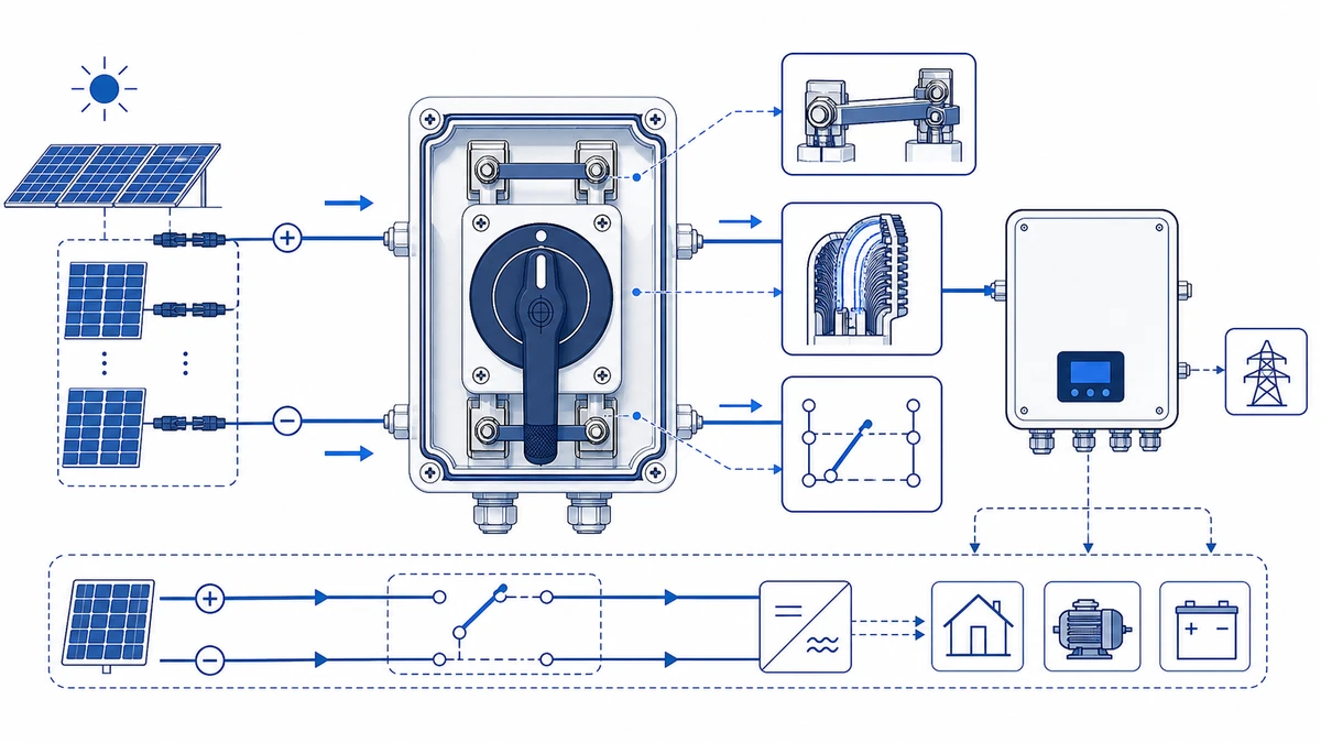
Unlike AC isolators, a GF40 PV DC isolator switch must suppress DC arcs without the natural current zero-crossing that extinguishes arcs in alternating-current circuits. The switch uses an extended contact gap geometry and arc quenching chamber sized specifically for DC breaking duty. When the rotary handle is turned to the OFF position, the contact bridge separates across a physical gap that must be sufficient to interrupt string current reliably at the rated voltage. The exact minimum gap is defined in the device datasheet and the applicable test program under IEC 60947-3.
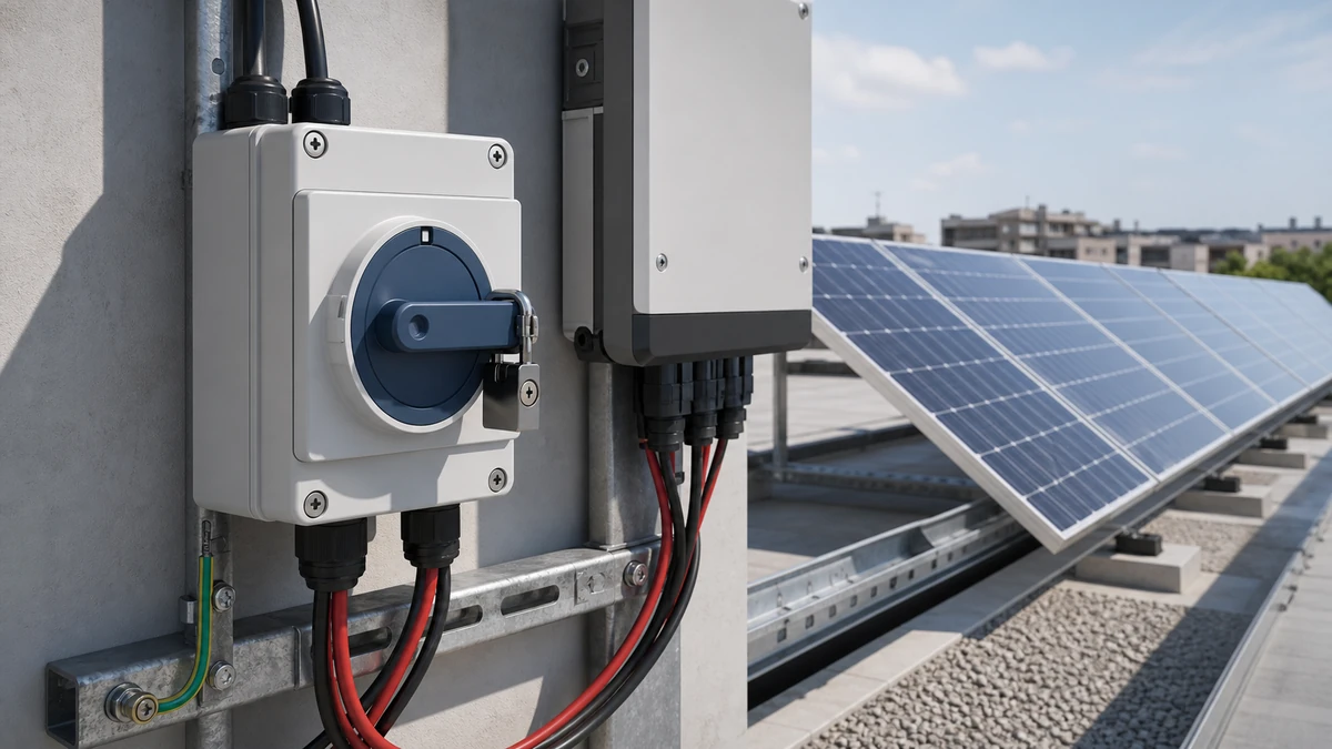
In a rooftop or ground-mount solar array, a GF40 isolator is typically installed at the DC input to an inverter or combiner box, allowing a service team to de-energize individual strings before opening the enclosure or performing insulation resistance testing. This placement aligns with safe-isolation practices covered by IEC 60947-3, the standard that governs switches, disconnectors, switch-disconnectors, and fuse-combination units for rated voltages up to 1000 V AC or 1500 V DC.
For a plain-language explanation of what a PV DC isolator switch does and where it fits in a solar system, see what is a PV DC isolator switch.
Those operating principles translate directly into a set of rated parameters that determine whether a GF40 is appropriate for a given solar string circuit.
Core Rating Parameters
The GF40 is rated for DC photovoltaic service, with a maximum working voltage up to 1000 V DC and model-dependent current ratings confirmed from the datasheet. These values align with residential and commercial string inverter systems, where open-circuit string voltages can approach the upper voltage class under cold, high-irradiance conditions.
The isolator is designed for utilization category DC-PV2, which governs making and breaking of PV string currents under load. This is a more demanding duty cycle than DC-PV1, which covers switching in an unloaded state only. Wherever a string can remain energized during an isolation operation, DC-PV2 is the minimum required category.
Applicable Standards
The GF40 is constructed and tested with reference to IEC 60947-3:2020+AMD1:2025, which applies to switches, disconnectors, switch-disconnectors, and fuse-combination units for distribution and motor circuits, with rated voltage up to 1000 V AC or 1500 V DC. For PV-specific DC switching duty, IEC 60947-2 Annex M provides the supplementary test regime covering arc interruption at elevated DC voltages. The current edition of IEC 60947-3 is available through the IEC webstore.
Enclosure ingress protection is classified to IEC 60529. The GF40 is typically available in IP65 or IP66 configurations — confirm the enclosure variant against the datasheet for the specific model selected.
GF40 Ratings Summary
Parameter
Typical Value
Governing Standard
Max. Rated Voltage (Ue)
Up to 1000 V DC
IEC 60947-3
Rated Current (Ie)
Model-dependent; confirm datasheet
IEC 60947-3
Utilization Category
DC-PV2
IEC 60947-3
Rated Insulation Voltage (Ui)
Up to 1000 V DC
IEC 60947-3
Enclosure Ingress Protection
IP65 or IP66
IEC 60529
Poles Available
2P, 4P
Confirm datasheet
All values in this table reflect typical figures for the GF40 family. Confirm exact ratings for the specific model code against the product datasheet before specifying or ordering.
Specifying to standards — four procurement checkpoints:
Request the test certificate referencing IEC 60947-3 and the PV DC switching annex from your supplier before placing an order. A CE mark alone does not confirm DC-PV2 duty rating.
Verify that the utilization category printed on the nameplate matches the datasheet. Mislabeled stock from secondary distributors is a documented procurement risk in solar projects.
When choosing between IP65 and IP66, treat coastal, high-humidity, and wash-down sites as reasons to review the higher ingress-protection option instead of relying on the baseline enclosure.
DC-PV2 category switches are evaluated for make-and-break duty under load. Do not substitute a DC-PV1 unit at a combiner position where strings may remain live during switching.
Key Components Inside a GF40 PV DC Isolator
Understanding the internal construction helps explain both the performance ratings above and the selection criteria that follow.
DC-Rated Contact Assembly
The contact bridge is the core switching element. In the GF40, silver alloy contacts — typically silver-tin oxide — are specified because DC arcs do not self-extinguish at current zero-crossings the way AC arcs do. The contact gap must be sufficient to reliably break string voltages up to the rated Ue under the breaking capacity requirements defined in IEC 60947-3. Exact contact material specification and gap dimensions are datasheet-dependent and vary by model variant.
Arc Quenching Chamber
Adjacent to each contact pair sits an arc quenching chamber with de-ion splitter plates or a magnetic blowout geometry. When the contacts open under load, the DC arc is stretched and cooled across the splitter plates, limiting contact erosion and preventing sustained arcing. This chamber is what separates a genuine PV DC isolator from a repurposed AC switching device.
Rotary Operating Mechanism
The GF40 uses a rotary actuator shaft connected to a cam-driven contact mechanism. Turning the handle through a defined arc — commonly 90 degrees — drives the contact bridges simultaneously across all poles. Multi-pole coordination is critical for 2-pole and 4-pole string configurations where all active conductors must open in a single operation.
IP-Rated Enclosure and Sealing
The outer enclosure on the GF40 PV DC isolator carries an IP65 or IP66 ingress protection rating per IEC 60529, meaning it is dust-tight and protected against water jets. Silicone or EPDM gaskets seal the cable entry points and the operating shaft interface. For a detailed explanation of what IP65, IP66, and IP67 ratings mean in practice for outdoor electrical hardware, see what is IP65, IP66, IP67.
Terminal Block and Cable Entry
Screw-type or box-lug terminals accept conductor cross-sections suited to the rated current of the selected model. Exact acceptable cable range, terminal torque values, and cable entry dimensions must be verified against the GF40 datasheet for the specific frame before wiring. Under-torquing causes resistive heating at the terminal; over-torquing can crack the terminal block body.
Figure 2. Selection checks should connect DC voltage, string current, pole count, enclosure, cable entry, and documentation.
How to Select the Right GF40 Variant
2P vs 4P Configuration
In a standard ungrounded PV string, current flows through a positive conductor and a negative conductor. A 2P GF40 isolates both conductors simultaneously with one pole assigned to each polarity. A 4P GF40 assigns two poles per polarity wired internally in series, which doubles the effective contact gap distance available to interrupt DC arc energy across the full rated voltage.
Because DC arcs do not self-extinguish at a natural current zero-crossing, the extended gap provided by a 4P arrangement is a meaningful design advantage at higher string voltages — typically where string open-circuit voltage approaches or exceeds 600 V DC. Below 600 V DC on a standard ungrounded string, a 2P unit is generally appropriate provided its rated voltage and current envelopes are confirmed against the datasheet.
GF40 2P vs 4P Selection Guide
Parameter
GF40 2P
GF40 4P
Poles
2
4
Typical voltage range
Up to 600 V DC
Up to 1000 V DC
Contact gap per polarity
Single gap
Double gap (series)
Recommended string Voc
Up to 600 V DC
600 V DC to 1000 V DC
String current (Isc)
Confirm against datasheet Ie
Confirm against datasheet Ie
Typical use case
Single-string residential rooftop
Multi-string commercial, higher-voltage arrays
Arc interruption suitability
Standard DC strings
Extended DC arc suppression
Confirm the specific voltage and current ratings for the selected model on the GF40 PV DC isolator switch product page before specifying. For installations where string voltage or current exceeds the GF40 envelope, the GF51 PV DC isolator switch offers an alternative worth evaluating in the same product family.
Always size against maximum Voc at the lowest expected cell temperature, not the nameplate operating voltage. In cold climates, Voc at minimum ambient can be materially above the nominal open-circuit voltage stated at standard test conditions.
Four selection rules for panel builders and procurement teams:
Use the lowest expected cell temperature for your site when calculating maximum Voc. Do not use the standard test condition of 25 degrees C as your design ceiling.
A 4P unit can add arc-interruption margin at higher string voltages, but it should still be selected against the confirmed wiring diagram, enclosure space, and datasheet rating.
At combiner-side positions feeding multiple strings in parallel, the combined short-circuit current of all strings flows through the isolator during a fault. Recalculate the current envelope against the full parallel string count, not a single string.
If your installation standard requires visible isolation evidence — an open-position window or a mechanical ON/OFF indicator — confirm the GF40 variant selected includes that feature before the unit reaches the site.
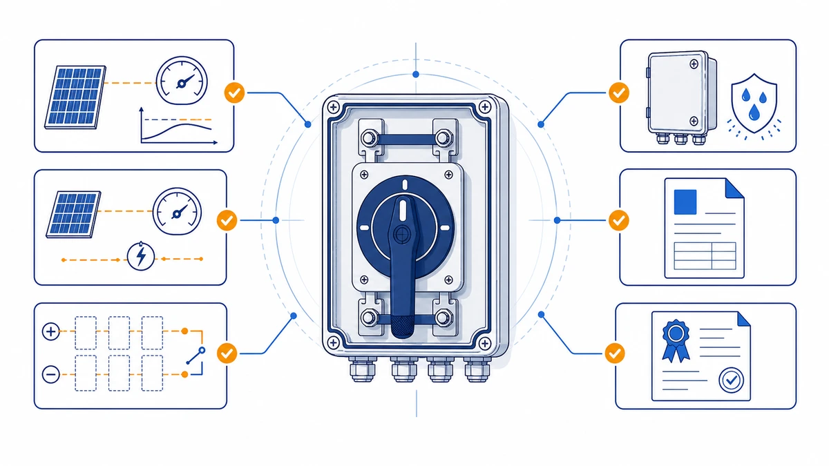
Figure 3. Application wiring context should be verified against the manufacturer contact chart before energizing.
Installing and Wiring a GF40 PV DC Isolator on Outdoor Solar Strings
Selecting the correct variant is half the work. Proper installation is what maintains that rating across the device’s full service life.
Pre-Installation Checks
Before mounting, verify these items against the switch datasheet and your system design document:
Confirm the GF40 voltage rating meets or exceeds the string maximum Voc at the lowest expected ambient temperature.
Check the current rating against string short-circuit current (Isc) multiplied by the applicable design factor required by your local PV installation standard, such as IEC 62548 or its national equivalent.
Inspect the enclosure IP rating. IP65 is a common outdoor baseline; verify whether your site conditions call for IP66 or another enclosure route.
Confirm cable entry orientation and conduit knockout positions suit the planned cable routing before fixing the final mounting location.
Mounting and Wiring Procedure
De-energize the PV string under the approved site lockout/shutdown procedure before beginning any wiring work; do not rely on improvised panel covering as the only isolation method.
Mount the isolator enclosure on a stable structural surface — a racking member, wall bracket, or DIN rail enclosure — using fasteners torqued to the manufacturer’s specified value to avoid cracking the housing.
Route positive and negative DC string conductors through separate cable glands. Maintain polarity markings throughout.
Terminate conductors to the input terminals (panel side) first, then to the output terminals (inverter side). Use ferrules on stranded cable to prevent strand splaying under terminal screws.
Torque terminal screws to the value stated on the datasheet.
Apply weatherproof sealing to all cable gland entries and verify the enclosure lid seats fully against its gasket before closing.
Post-Installation Verification
With the isolator in the OFF position, use a calibrated DC voltmeter and the approved commissioning procedure to verify the expected input and output terminal conditions.
Operate the handle through at least two full ON/OFF cycles to confirm positive switching action and audible engagement.
Label the isolator with string identifier, rated voltage, and rated current in accordance with site documentation requirements.
For background on DC switch-disconnector terminology, compare the device marking with the product datasheet and the applicable installation standard before specifying.
How Shieldhz Confirms GF40 Configuration and Documentation for Solar Projects
Shieldhz is the export brand of Zhejiang Shihe Electric Co., Ltd., founded in 2014 and based in Yueqing, Wenzhou, Zhejiang. The facility covers more than 5,000 square meters, operates with 100-plus employees and 40-plus production machines, and holds ISO 9001 quality management certification alongside CE, RoHS, TUV, UL, UKCA, CCC, and CB approvals relevant to specific product lines.
When a project inquiry arrives for a GF40 PV DC isolator, the engineering team works through a structured confirmation process before a model code and documentation package are released.
Step 1 — Electrical rating intake. The process starts with four core inputs from the buyer: maximum string open-circuit voltage, maximum string short-circuit current, required pole count (2P or 4P), and the applicable installation standard for the target market. These inputs are cross-referenced against the GF40’s rated insulation voltage (Ui), rated operational current (Ie), and IEC 60947-3 utilization category. If the submitted string voltage approaches the upper boundary of the 2P model envelope, engineers typically recommend the 4P series configuration, which distributes the DC arc interruption duty across two poles per conductor rather than one.
Step 2 — Enclosure and IP selection. Outdoor solar string environments commonly start with an IP65-class enclosure under IEC 60529. For projects in coastal zones, high-humidity climates, or sites subject to regular high-pressure wash-down, the review determines whether IP66 or IP67 classification is appropriate for the enclosure variant specified.
Step 3 — Contact program and wiring diagram review. Before production release, Shieldhz prepares a wiring diagram matched to the confirmed pole configuration and verifies terminal sizing against the submitted cable cross-section. This step prevents field rework caused by undersized terminal lugs or incorrect polarity labeling on the assembled unit.
Step 4 — Documentation package release. The final package includes the product datasheet, panel cutout drawing, and applicable test certificates. For export projects requiring CE marking or compliance documentation referencing IEC 60947-3 and IEC 62109-1, the certificate set is reviewed against the destination market requirement before shipment confirmation.
Buyers who need to compare the GF40 against an adjacent frame for a different current or voltage profile can review the full DC isolator switch range to identify the appropriate model route before submitting an inquiry.
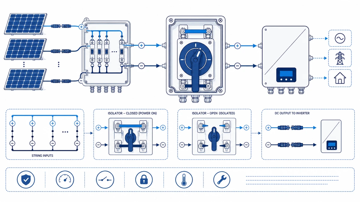
Figure 4. A complete inquiry should include rating, contact sequence, mounting, enclosure, and document requirements.
Frequently Asked Questions
What does the utilization category DC-PV2 mean for a GF40 isolator?
DC-PV2 is the IEC 60947-3 duty classification for switches evaluated to make and break PV string current under load. DC-PV1 covers switching in an unloaded state only. In any position where a string may remain energized during an isolation operation, the datasheet should confirm a load-break DC photovoltaic duty category rather than a no-load-only rating.
Can a standard AC isolator be used in place of a GF40 PV DC isolator switch?
No. An AC-rated isolator lacks the extended contact gap geometry and arc quenching chamber required to suppress DC arcs. DC arcs do not self-extinguish at a natural current zero-crossing the way AC arcs do. Using an AC device in a DC solar string creates a sustained arc risk that can cause contact welding, enclosure fire, or a failure to achieve safe isolation — none of which are recoverable situations on an energized rooftop.
How do I calculate the correct GF40 current rating for my string?
Identify the short-circuit current (Isc) of your PV string from the module datasheet, then apply the design factor required by the applicable installation standard and project specification. The resulting value must fall at or below the GF40 rated operational current (Ie) for the selected model. At combiner positions where multiple strings are paralleled, calculate the combined Isc of all connected strings before comparing against the device rating.
What is the difference between IP65 and IP66 for outdoor solar installations?
IP65 confirms dust-tight sealing and protection against low-pressure water jets from any direction. IP66 adds resistance to powerful direct water jets, which is relevant for sites subject to high-pressure cleaning, heavy sustained rainfall, or salt-spray exposure. Both ratings are defined under IEC 60529. IP66 is the safer default for installations near coastlines or where wash-down maintenance is routine. Neither rating covers prolonged submersion, which requires IP67 or IP68.
At what point should a 4-pole GF40 be chosen over a 2-pole unit?
A 4-pole configuration becomes appropriate when string open-circuit voltage approaches or exceeds 600 V DC. The internal series arrangement of two poles per conductor doubles the effective contact gap available to interrupt the DC arc. Below 600 V DC on a standard ungrounded string, a 2-pole unit is generally sufficient provided its rated voltage and current envelopes are confirmed against the datasheet. When in doubt, the 4P option adds arc interruption margin without adding installation complexity.
What documentation should accompany a GF40 shipment for a certified solar installation?
A documentation package for a certified solar installation should include the product datasheet confirming IEC 60947-3 ratings and the applicable DC photovoltaic utilization category, the IEC 60529 ingress protection evidence, and any market-specific approvals such as CE marking or TUV documentation where applicable. A wiring diagram matched to the confirmed pole configuration and a terminal torque specification sheet are standard items that installers need before commissioning. Request these before order confirmation, not after delivery.
Is the GF40 suitable for battery storage DC circuits as well as solar strings?
The GF40 is rated and tested specifically for PV array DC string isolation duty. Battery storage circuits operate under different fault current profiles, voltage recovery characteristics, and discharge curves that may require a device tested to different breaking capacity criteria. Confirm with the Shieldhz engineering team whether the rated breaking capacity and utilization category of the selected GF40 variant are appropriate for the specific battery system topology before specifying it outside a PV string application.
Shi, Muxi
Shi, Muxi writes Shieldhz technical articles for industrial control and electrical component buyers, covering rotary cam switches, isolator switches, PV DC disconnects, push buttons, indicator lights, waterproof enclosures, and terminal blocks. The articles are based on Zhejiang Shihe Electric Co., Ltd.'s manufacturing and export experience, with practical emphasis on model selection, datasheets, drawings, certifications, IP ratings, and inquiry details buyers should confirm before ordering.