DC isolation points in PV string combiners and inverters are defined switching positions where the DC circuit is fully disconnected, creating a de-energized, touch-safe state for maintenance or fault response. They interrupt current flow from solar strings, which typically operate between 600 V DC and 1,500 V DC, before that current reaches downstream equipment or personnel. Selecting and placing these isolation points correctly determines whether a PV installation satisfies IEC 60364-7-712, IEC 60947-3:2020+AMD1:2025, or NEC Article 690 requirements. This article explains how each isolation point works, what components it contains, how string combiner and inverter DC disconnects differ, and how to verify isolation safely in the field.
What Are DC Isolation Points in PV String Combiners and Inverters?
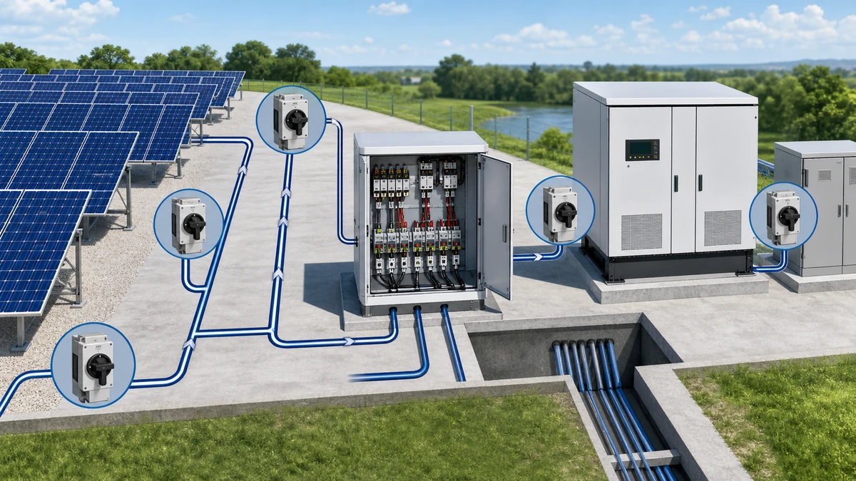
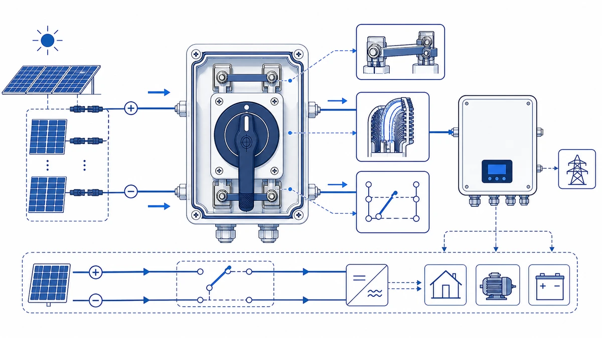
In a grid-tied solar installation, DC power flows from individual PV strings through a string combiner box, along a DC trunk cable, and into the inverter’s DC input terminals. Each of these transition points represents a potential fault exposure zone. A DC isolation point, implemented as a rated isolator switch or disconnector, creates a verified open-circuit gap within this path.
For string combiners, the isolation point is typically located at the combiner output, allowing service teams to disconnect the aggregated string current before accessing fuse holders, surge protective devices, or wiring terminals. For inverters, an integrated or externally mounted DC isolator is positioned between the combiner output and the inverter DC bus, satisfying requirements under IEC 60364-7-712 and equivalent national codes.
An isolation point is functional only when its components are rated for the actual DC operating parameters. In residential rooftop systems this typically means a disconnector rated at 1,000 V DC with a breaking capacity matched to the maximum short-circuit current of the combined strings. In utility-scale arrays operating at 1,500 V DC the requirements are considerably more demanding, because DC arc energy increases significantly at higher voltages.
Shieldhz’s PV DC isolator switch range is designed specifically for these isolation duties, where voltage class, pole configuration, and enclosure IP rating must all align with the installation environment.
How PV String Combiners Work and Why Isolation Is Built In
A PV string combiner aggregates the DC output of multiple series-connected solar strings into a single feed before that power reaches the inverter. Each string typically operates at open-circuit voltages between 600 V DC and 1,500 V DC, and the combiner’s role is to sum the string currents in parallel while keeping each source electrically distinguishable for protection and maintenance purposes.
Current Aggregation and the Parallel Bus
When strings are paralleled at the combiner’s positive and negative bus bars, their currents add directly. A system with eight strings each delivering 10 A at maximum power point produces 80 A at the combiner output terminals. This additive behavior follows Kirchhoff’s Current Law. The practical consequence is that if one string develops a fault, such as a ground fault or partial shading mismatch, it can become a sink for reverse current from the healthy strings rather than a source.
Per-String Fusing and Disconnection
To prevent destructive reverse current flow, each string input is protected by a series-connected DC fuse rated for the maximum reverse current the string wiring can sustain. A fuse that opens under reverse-current stress must interrupt a DC arc without restrike, a more demanding task than AC interruption because there is no natural current zero crossing.
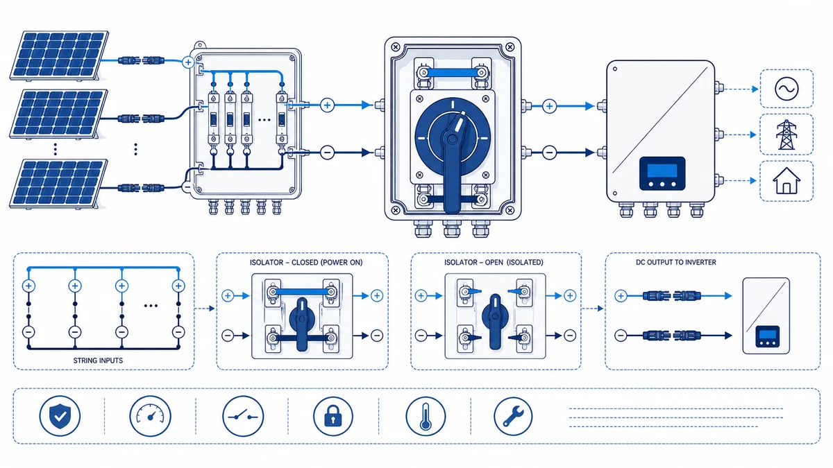
Beyond fusing, well-designed combiners incorporate a per-string disconnect for each input. In a rooftop commercial installation this allows a maintenance team to isolate one underperforming string for testing without de-energizing the entire array or shutting down the inverter. The combiner output also carries a main DC isolator that creates a verified open point between the combiner bus and the inverter DC input terminals. This main isolator must be rated for the full combined string voltage and aggregated current.
Together, per-string fusing, per-string disconnection, and a combiner output isolator form a layered isolation architecture that satisfies both fault protection and safe-work requirements under applicable installation codes.
Field tip – string commissioning: When commissioning a new combiner, measure each string’s open-circuit voltage individually before closing any string fuse, then compare values. A string reading more than 5 percent below the calculated Voc often signals a shading, polarity, or module-count error before the circuit is ever loaded.
Field tip – fuse verification: Never assume a blown fuse has fully cleared the string from the bus. Probe both sides of the fuse holder with a CAT III or CAT IV rated meter before reaching into the fuse cavity, because a failed fuse can retain partial continuity and still present voltage.
Field tip – temperature derating: In high-ambient-temperature enclosures above 45 degrees C at the combiner, derate fuse ampacity per the manufacturer’s derating curve. Insufficient derating is one of the most common causes of nuisance fuse opening during peak summer irradiance.
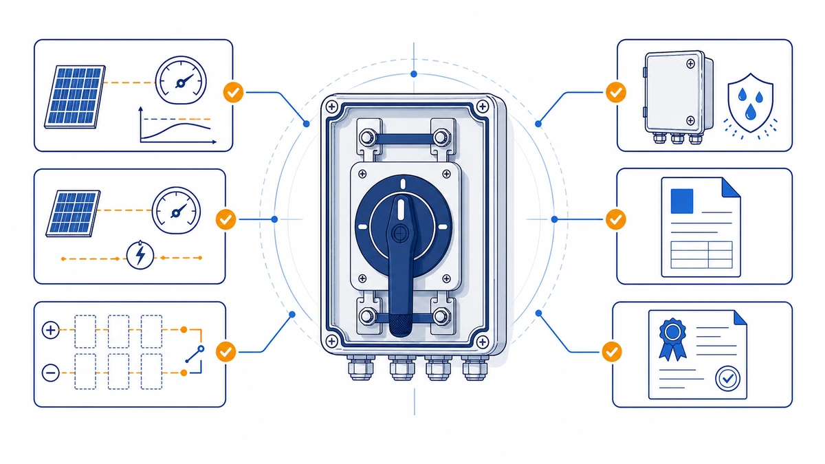
Figure 2. Selection checks should connect DC voltage, string current, pole count, enclosure, cable entry, and documentation.
Key Components at Each DC Isolation Point
Each DC isolation point in a PV string combiner or inverter circuit contains a defined set of components working together to create a safe, serviceable disconnect zone. The selection of each component is governed by the same underlying standards that define the isolation point itself.
Disconnect Switches
The primary switching element at any DC isolation point is a rated DC disconnect switch or DC isolator. Unlike AC breakers, DC-rated switches must interrupt current without the natural zero-crossing that extinguishes AC arcs. For string-level combiners, isolators are typically selected to handle open-circuit voltages up to 1,000 V DC or 1,500 V DC, with a continuous current rating matched to combined string current. IEC 60947-3:2020+AMD1:2025 applies to switches, disconnectors, switch-disconnectors, and fuse-combination units for distribution and motor circuits, with rated voltage up to 1000 V AC or 1500 V DC, and its utilization categories define the make-and-break duty each device must demonstrate.
For background on how this standard applies to PV disconnectors, the IEC 60947-3 overview provides a useful starting point before checking individual product datasheets.
Fuse Holders and String Overcurrent Protection
String fuse holders occupy the combiner box tier, positioned on each string’s positive conductor. Fuse holders must be rated for DC voltage. AC-rated fuse carriers are not interchangeable due to arc extinction differences. Fuse current and voltage ratings must be confirmed from the module datasheet and array configuration documentation before selection.
Surge Protection Devices
Type II DC surge protective devices are installed at combiner bus bars to clamp transient overvoltages caused by lightning or switching events. SPDs are wired line-to-line and line-to-ground, with a maximum continuous operating voltage exceeding the system’s maximum open-circuit voltage. Ratings are verified from the SPD datasheet against the specific array Voc for the installation site’s temperature range.
Bus Architecture
The positive and negative bus bars in a combiner box aggregate multiple string conductors into a single output feed. Insulated barriers maintain creepage distances per IEC 60664-1 for the applicable pollution degree. The bus rating is confirmed from the enclosure and bus bar manufacturer’s datasheet for each combiner configuration.
String Combiner Isolation vs. Inverter DC Disconnect: What Is the Difference?
Both a string combiner isolation point and an inverter DC disconnect interrupt DC current in a PV system, but their roles diverge in ways that directly determine which component ratings, switching categories, and compliance labels apply to each position.
Parameter
String Combiner Isolation
Inverter DC Disconnect
Location
Inside or adjacent to the combiner box, upstream of DC bus
At inverter DC input terminals, between DC bus and inverter
Typical voltage rating
Per-string Voc multiplied by the applicable safety factor, often up to 1,000 V DC
Full array Voc; up to 1,000 V DC for residential or commercial, up to 1,500 V DC for utility-scale
Typical current rating
Single-string Isc; sized per the OCPD on each string input
Combined array current; rated for the full DC input current of the inverter
Switching purpose
Isolates individual strings for maintenance, fault clearance, or OCPD coordination
Creates a system-level off-state to safely de-energize the inverter DC side for service or emergency shutdown
Applicable standard
IEC 60947-3; NEC Article 690.15
IEC 60947-3; IEC 62109-1; NEC Article 690.13
Operator access
Typically a qualified electrical worker during commissioning or fault response
Must be accessible and operable by first responders under rapid shutdown provisions; labeled per installation code
In a rooftop commercial installation, string combiner isolators are selected around individual string parameters, while the inverter DC disconnect must be rated for the full combined current entering the inverter, a value that can exceed 50 A DC at higher array configurations.
The GF40 PV DC isolator switch is suited to string combiner locations, where per-string voltage and current ratings must be verified against the specific module datasheet and array configuration before selection.
Field tip – inverter-side conductor status: Even with the inverter DC disconnect open and the inverter displaying isolated, the conductors on the array side of the disconnect remain live during daylight. Always verify with a meter at the disconnect’s line-side terminals before working on any upstream conductor.
Field tip – utility-scale multiple feeds: Utility-scale inverters often have multiple DC input combiners feeding a single DC bus. Confirm which specific combiner feed you have isolated and affix a personal lockout device before assuming the full inverter DC side is de-energized.
Field tip – rapid shutdown timing: Where NEC 690.12 applies, verify that inverter-side DC voltage drops to the required level within the specified time window during commissioning, using a data-logging meter on the DC bus rather than relying solely on the inverter’s own status display.
Figure 3. Application wiring context should be verified against the manufacturer contact chart before energizing.
How to Safely Test and Verify DC Isolation in the Field
Field verification of DC isolation at the string combiner and inverter DC input should be performed only by qualified electrical personnel using the site method statement, calibrated instruments, and project safety procedure. A blog article cannot replace the local lockout/tagout procedure or the installer’s risk assessment.
Qualified-Person Verification Requirements
Before any field test, qualified personnel should confirm the PPE category, instrument voltage category, lockout/tagout steps, and insulation-test method from the project procedure and local electrical code. Meter category, test voltage, and acceptance limits must come from the approved commissioning plan rather than from a generic blog checklist.
Isolation Verification Procedure
Step 1 – Pre-isolation measurement: With all combiner string fuses intact and the inverter running, record live DC bus voltage between positive and negative terminals at the combiner output. Document the value as the baseline.
Step 2 – Open the combiner DC isolator: Operate the DC isolator switch to the OFF position.
Step 3 – Confirm voltage collapse at the combiner output: Place multimeter probes on the load-side terminals of the isolator. A reading at or near 0 V DC confirms the switch has interrupted the bus. A residual reading above 5 V DC indicates a possible switching failure or parallel back-feed path requiring investigation before proceeding.
Step 4 – Open the inverter DC input isolator: Operate the inverter-side DC disconnect. A PV-rated DC isolator with a utilization category appropriate for PV source circuits per IEC 60364-7-712 is the standard choice for this position.
Step 5 – Verify zero voltage at inverter DC terminals: Confirm a reading at or below 1 V DC at the inverter positive and negative input terminals before removing any connections.
Step 6 – Insulation resistance test: Perform the insulation resistance test only under the approved commissioning procedure, using the test voltage, soak time, and acceptance threshold specified for the system voltage class. Abnormal readings should be investigated before re-energizing.
Technicians perform Steps 1 through 6 sequentially for each string, treating each string as independently energized until its individual measurement confirms isolation.
NEC 690, IEC 60364-7-712, and What Standards Require at DC Isolation Points
Regulatory compliance at DC isolation points is not a post-installation checkbox. The voltage ratings, labeling requirements, and accessibility rules defined by NEC 690 and IEC 60364-7-712 must be resolved during component selection, before a single conductor is terminated.
Requirement
NEC Article 690 (USA)
IEC 60364-7-712 (International)
Disconnect location
At each PV source circuit, output circuit, and inverter DC input; within sight or lockable
At array connection points and between array and inverter; accessible to authorized persons
Labeling
Marked with maximum rated DC voltage, maximum rated current, and PV SYSTEM DISCONNECT
Marked with rated voltage, current, and polarity; warning labels for live DC conductors
Voltage rating
Rated for system maximum DC voltage; residential cap applies unless listed equipment exceeds it
Rated per system Voc multiplied by the applicable safety factor per IEC 60664-1
Current rating
Must interrupt maximum short-circuit current under load
Must carry and interrupt Isc with appropriate utilization category per IEC 60947-3
Accessibility
Accessible to qualified persons; lockable open position required
Accessible to skilled or instructed persons; lockout provision recommended
Grouping
String combiner disconnects may be grouped; each circuit individually identifiable
Individual string isolation permitted at combiner level; grouped arrays must allow individual de-energization
IEC 60364-7-712 requires equipment rated at no less than 1.25 times Voc. For a string where module-level Voc values are confirmed from the manufacturer’s datasheet, this calculation must be completed for the worst-case low-temperature condition at the installation site before a disconnect voltage class is confirmed.
For PV-rated DC isolators designed to satisfy both frameworks, the applicable IEC 60947-3 utilization categories define whether a switch can merely carry continuous current or must also make and break a loaded DC circuit. Selecting a disconnect rated for utilization category DC-22B ensures the device is verified for loaded make-and-break duty, which is the condition present when opening a live PV string at the combiner or inverter input.
Understanding the full scope of what a PV DC isolator switch is before specifying a product is an important first step in confirming that the selected device matches both the regulatory framework and the actual switching duty.
Figure 4. A complete inquiry should include rating, contact sequence, mounting, enclosure, and document requirements.
How Shieldhz Confirms the DC Isolation Switch Specification for PV Combiner Applications
Shieldhz is the export brand of Zhejiang Shihe Electric Co., Ltd., founded in 2014 and based in Yueqing, Wenzhou, Zhejiang Province. The company operates a factory of over 5,000 square meters with more than 100 employees and 40 production machines. Certifications available across the product range include ISO 9001, CE, TUV, RoHS, UL, UKCA, CCC, and CB, with applicability confirmed per specific model and target market.
Specifying a DC isolation switch for a PV combiner or inverter DC input requires confirming several parameters before a model is matched. For each inquiry, Shieldhz’s engineering team works through the following inputs with the buyer.
Maximum open-circuit voltage: The rated insulation voltage Ui of the selected switch must meet or exceed the PV array’s Voc calculated under the worst-case low-temperature condition at the installation site. This is verified from the module manufacturer’s datasheet alongside the array configuration document.
Maximum DC current per pole: Breaking capacity at the operating DC utilization category is confirmed against the combined string current or the full inverter DC input current, depending on the isolation point position. The relevant rating is drawn from the product datasheet for the specific model under consideration.
Pole count: Two-pole configurations are standard for ungrounded string circuits. Four-pole variants are specified where both positive and negative conductors require simultaneous isolation. The wiring diagram for the combiner box or inverter DC input is reviewed to confirm which configuration applies.
Enclosure and IP rating: Rooftop and outdoor ground-mount combiner boxes typically require IP65 or IP66 ingress protection per IEC 60529. Coastal or chemically aggressive environments may require additional enclosure material specifications. Shieldhz confirms the IP class from the product’s test documentation, not from a generic claim.
Certification documentation package: CE marking, TUV PV component evaluation, or market-specific compliance evidence is confirmed against the selected model’s available test reports and certificate numbers before quotation. Buyers specifying for UL-listed or UKCA-marked projects receive confirmation of which models carry the relevant mark from current documentation.
Wiring diagram and mounting drawing: Shieldhz provides the applicable wiring diagram and panel or DIN-rail mounting drawing as part of the documentation package for each confirmed model. For combiner box builders and OEM panel builders, this drawing package is included with the datasheet at the quotation stage.
The GF40 PV DC isolator switch and GF41 solar DC switch are among the models most commonly matched to string-level and combiner output isolation duty. The GF51 PV DC isolator switch is frequently specified for inverter DC input positions where a higher combined current rating is required. All model matches are subject to the buyer’s system parameters and the confirmed datasheet ratings for the specific production batch.
If you are sizing a DC isolation point for a PV combiner box or inverter DC input, provide your system voltage, current rating per pole, pole requirement, enclosure IP class, target certification, and installation standard. Shieldhz’s engineering team will confirm the correct model, contact program, wiring diagram, mounting drawing, and documentation package for your application.
Frequently Asked Questions
What is the difference between a DC isolator and a DC circuit breaker in a PV system?
A DC isolator creates a verified open-circuit gap to de-energize a circuit for safe working, but it is not designed to interrupt fault-level overcurrent automatically. A DC circuit breaker provides both switching and automatic overcurrent protection, tripping under short-circuit or overload conditions without manual intervention. In most PV string combiner designs, both are present: per-string fuses or circuit breakers handle overcurrent protection, while the combiner output isolator and inverter DC disconnect handle maintenance isolation duty.
Can a standard AC-rated disconnect switch be used at a PV string combiner output?
AC-rated devices are not suitable for DC isolation duty. DC arcs lack the natural current zero-crossing that allows AC devices to extinguish them reliably. Using an AC-rated switch at a DC isolation point risks sustained arcing, contact welding, and potential fire under fault conditions. The product datasheet and voltage/utilization category marking must confirm DC suitability before a device is installed at any PV isolation point.
How many DC isolation points does a typical string combiner require?
A well-specified string combiner includes one isolation point per string input, usually a fuse rather than a full switch-disconnector, plus one main DC isolator at the combiner output. Larger arrays may also include intermediate bus-section isolation to allow partial de-energization during maintenance without shutting down the entire combiner.
What IP rating is required for an outdoor PV string combiner isolation switch?
Outdoor rooftop and ground-mount installations commonly use IP65 or higher, depending on exposure. Coastal or high-humidity environments may require IP66 or additional corrosion-resistant enclosure materials. The required IP class is determined by the installation environment assessment and confirmed from the product’s test documentation. A detailed explanation of the differences between IP65, IP66, and IP67 is available in the IEC 60529 IP-rating guidance.
Why does DC arc energy increase at higher system voltages?
Arc energy in a DC circuit increases with voltage because a higher potential difference sustains the plasma column across a wider contact gap and for a longer duration. At 1,500 V DC, an isolation switch must extinguish an arc that contains significantly more energy than at 600 V DC, which is why voltage class is the first parameter verified during component selection. This is also why IEC 60947-3 defines separate utilization categories and test conditions for different voltage classes.
How often should DC isolation points be tested in an operating PV system?
Many operations and maintenance plans include scheduled functional verification of DC isolation points, with additional checks after a fault event, lightning strike, or significant physical disturbance to the array. Insulation resistance testing may be included in the same maintenance plan to detect conductor degradation before it develops into a ground fault. The specific interval should be confirmed from the O&M plan, owner requirements, and local electrical rules for each installation.
What does utilization category DC-22B mean for a PV isolator switch?
DC-22B per IEC 60947-3:2020+AMD1:2025 defines a switching duty that includes making and breaking mixed resistive and inductive DC loads under load current, which covers the conditions present when opening a live PV string circuit. A switch rated only for DC-21B is verified for resistive load switching but is not evaluated for the more demanding inductive make-and-break duty encountered at PV combiner and inverter isolation points. Confirming the utilization category from the product datasheet is a required specification check for any PV DC isolation switch.
Shi, Muxi
Shi, Muxi writes Shieldhz technical articles for industrial control and electrical component buyers, covering rotary cam switches, isolator switches, PV DC disconnects, push buttons, indicator lights, waterproof enclosures, and terminal blocks. The articles are based on Zhejiang Shihe Electric Co., Ltd.'s manufacturing and export experience, with practical emphasis on model selection, datasheets, drawings, certifications, IP ratings, and inquiry details buyers should confirm before ordering.